U.S. Department of Transportation
Federal Highway Administration
1200 New Jersey Avenue, SE
Washington, DC 20590
202-366-4000


Skip to content
Facebook iconYouTube iconTwitter iconFlickr iconLinkedInInstagram

Federal Highway Administration Research and Technology
Coordinating, Developing, and Delivering Highway Transportation Innovations

Report
This report is an archived publication and may contain dated technical, contact, and link information
Publication Number: FHWA-HRT-06-139
Date: October 2006

Traffic Detector Handbook:Third Edition—Volume II

APPENDIX A. INDUCTIVE-LOOP SYSTEM EQUIVALENT CIRCUIT MODEL

ABSTRACT

The equivalent electrical circuit model for an inductive-loop system allows the loop’s inductance and quality factor to be calculated.

Appendix A describes the derivation and application of an equivalent circuit model and computer program that calculates the apparent self-inductance and quality factor versus frequency of square, rectangular, quadrupole, and circular loops of round wire buried in a roadway. The effects of transmission lines and matching transformers between the loop in the roadway and roadside electronics units are included in the model. The capacitance between the loop conductors and surrounding pavement material is shown to have a major effect on the magnitude of the loop’s apparent self-inductance.

Inductive-loop detectors are commonly used in actuated and computer–controlled traffic surveillance systems. The size, shape, and number of turns of wire in the loop should be designed to provide adequate vehicle detection sensitivity and prevent the lead-in wire and lead-in cable from reducing sensitivity. The inductance value at the input to the electronics unit must be within the range specified by the unit’s manufacturer. The computer program described in this appendix allows engineers to calculate the apparent loop inductance and quality factor versus operating frequency (20–60 kHz) for selected loop size, shape, wire diameter, number of turns, turn spacing, slot width, pavement loss tangent, and slot sealant dielectric constant.

INTRODUCTION

An inductive-loop detector system is composed of a buried loop of wire in the roadway pavement, which is connected with a transmission line (i.e., lead-in wire and lead-in cable) to a roadside electronics unit. When a vehicle is sensed by the loop, a small decrease in loop inductance is detected by the electronics unit. Furthermore, since the series inductance of the transmission line decreases the magnitude of the inductance change at the input to the electronics unit, the loop inductance should be larger than the transmission line series inductance. The loop inductance can be increased by winding additional turns into the loop and adding a transformer between the loop and transmission line.

The frequency range of typical electronics units is 20–60 kHz, although newer units that provide vehicle classification can operate at hundreds of kilohertz. Loop capacitance can cause the inductance sensed by the electronics unit to change significantly with frequency if too many turns are used in the roadway loop. To better predict inductive-loop system performance, an equivalent circuit model of the loop system was developed and programmed on a computer. The computer program allows inductiveloop system designers and maintenance technicians to calculate the detection system inductance and quality factor as a function of frequency, wire gauge size, wire spacing, etc.

The equivalent loop system model contains a roadway inductive-loop model, a transformer model, and a transmission line model. The calculation of the self-inductance of square, rectangular, and quadrupole loops is described elsewhere.(1,2) King describes the calculation of the self-inductance of circular loops.(3) This appendix expands the model to include the internal and external capacitance of such loops so that the high-frequency performance of the loop system can be calculated. A wideband transformer model is used. The transmission line model incorporates a complex characteristic impedance. All equations used in the loop computer program are included in this appendix.

LOOP CAPACITANCE THEORY

INTERNAL-LOOP CAPACITANCE

The stray capacitance between turns of wire in an inductive loop is calculated using a multilayer transformer model.

The capacitance between loop turns is calculated using a low-frequency, multilayer, transformer model.(4) The model assumes uniform flux coupling through the loop turns with minimum leakage flux. Figure A-1 illustrates the capacitance between two adjacent isolated loop turns.
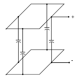
FIGURE A-1 shows that the capacitance between adjacent isolated loop turns may be modeled through the use of capacitance between the adjacent segments

Figure A-1. Capacitance between adjacent isolated loop turns.

The loop wires are modeled as parallel transmission lines that have a capacitance per unit length C' of (5)

Equation A-1. C prime is equal to the quotient of the product of the quotient of epsilon over epsilon subscript 0, and 10 raised to the negative ninth power, all over the product of 36, the inverse hyperbolic cosine of D all over the product of 2 and A. (A-1)
where  
D= spacing between conductor centers (m)
a= conductor radius (m)
ε/ε0= relative dielectric constant of the material that surrounds the turns of wire (equal to 1 for air)
ε0= permittivity of free space = 8.854 x 10⁻¹² F/m.

The total capacitance between adjacent but isolated loop turns is given by

Equation A-2. C superscript i is equal to the product of C prime times P. (A-2)

where P is the loop perimeter (m). A similar method was used by Palermo.(6) The actual loop turns are connected as shown in figure A-2.
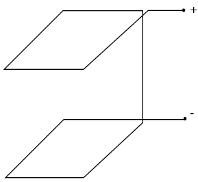
Figure A-2 shows that the total capacitance may be modeled as the capacitance per unit length times the perimeter.

Figure A-2. Connection of adjacent loop turns.

The parallel transmission line is shorted at the end. The input capacitance of the shorted transmission line is given by

Equation A-3. C subscript T superscript i is equal to the Integral from 0 to P of the product of the squared quotient of x divided by P times C prime, integrated with respect to x, which is equal to the product of one-third, capitol C prime, and capitol P. (A-3)

Figure A-3 shows the circuit model for a multiturn loop, where LL represents the low-frequency inductance of the loop and CLi the lumped internal capacitance across the loop terminals.
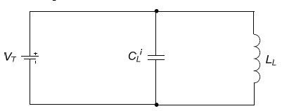
Figure A-3 show that the capacitance modeled in figures A-1 and A-2 may also be modeled with a circuit model with L sub L the low frequency inductance and C sub L the lumped internal capacitance balances the equivalent inductance L sub L across the parallel circuit.

Figure A-3. Multiturn loop equivalent circuit model.

The total internal energy stored in the capacitor is

Equation A-4. E subscript Tau is equal to the product of 0.5, C superscript I subscript L, and V squared subscript Tau, which is equal to the product of one-half and the quantity of the sum from J equals 2 to N of the product of C subscript J superscript I, and V squared subscript J. (A-4)

When the voltage drop is linear, the voltage across each turn is directly proportional to the total voltage drop and inversely proportional to the number of turns. Accordingly,

Equation A-5. V subscript j is equal to the product of 2, and V subscript T, divided by n. (A-5)

and

Equation A-6. C subscript L superscript I is equal to the summation from J equals 2 to N of the quantity of the product of the quotient of capitol C prime times 2 all over 3, time the squared quotient of 2 over n, end expression. (A-6)

where n is equal to the number of loop turns.

The lumped internal capacitance across the loop terminals is given by

Equation A-7. C subscript L superscript I equals the product of four-thirds, and the quotient of N minus 1 all over N squared, time C prime, times P. (A-7)

This equation is identical to the equation for the capacitance between transformer winding layers with the exception of C'.(7)

EXTERNAL-LOOP CAPACITANCE

External capacitance is created when a conductor is located in the vicinity of a dielectric material. This does not occur when a conductor is placed near another conducting surface such as a metal. Figure A-4 illustrates capacitive coupling between turns of loop wire (i.e., the conductor) and the edge boundaries of a sawcut or sealant (i.e., the dielectric). The dielectric constant of the material surrounding the wire is denoted by ε and its conductivity by σ. Since loop wires are typically closer to the top of the slot (i.e., sealant in the bottom of the slot supports the loop wire), the capacitive coupling between the wire and bottom of the slot was neglected.
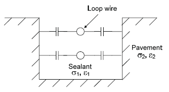
Figure A-4 shows that the capacitive coupling which occurs between loop wires in the loop sealant and the walls of the sawcut may be modeled using their values for epsilon, the relative dielectric constant, and for sigma, the conductivity, respectively.

Figure A-4. Capacitance between loop conductors and slot.

Galejs determines the impedance of a buried insulated wire.(8) The capacitance is calculated assuming the region surrounding the slot or cavity is finitely conducting. If region one is composed of low-loss dielectric, we can write(9)

Equation A-8. The absolute Value of product of j times omega times epsilon subscript 1 is greater than sigma subscript 1. (A-8)

Stratton also shows that a perfectly conducting outer conductor, as found in a coaxial line, provides a good approximation to a finitely conducting one when calculating shunt admittance.(10) The slot walls are approximated by infinitely conducting ground planes, as illustrated in Figure A-5. These observations allow the combination of a coaxial conductor and TEM transmission line for use in modeling the capacitance of loop wires embedded in a slot.
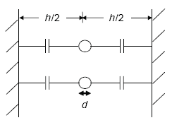
Figure A-5 shows that the capacitive coupling which occurs between loop wires in the loop sealant and the walls of the saw cut may be approximated by infinitely conducting ground planes at a distance of 0.5 H instead of finitely conducting saw cut walls. Note that H is the width of the saw cut.

Figure A-5. Capacitance between loop conductors and infinitely conducting planes.

The characteristic impedance Z0 of a coaxial conductor is given by(11)

Equation A-9. Z subscript 0 equals the product of the quotient of 138 over the square root of E subscript R, times the log base 10 of the quantity of the quotient of 4 times h all over the product of pi and d. (A-9)
where  
 h = sawcut slot width
 d = diameter of loop wire.

The capacitance per unit length of a TEM transmission line is expressed as

Equation A-10. C prime equals the quotient of the product of 120, pi, epsilon subscript 0, and the square root of epsilon subscript R, all over Z subscript zero. (A-10)

Thus

Equation A-11. C prime equals the quotient of the product in the numerator of 2, pi, epsilon subscript 0, and epsilon subscript r, all over all the natural logarithm of the quantity of the quotient of 4 times h all over pi times d. (A-11)

or

Equation A-12. C prime equals the product of the quotient of 1 over 18, times the quotient of the numerator product of epsilon subscript R and 10 raised to the negative 9 power, all over the denominator natural log of the quotient of 4 times H all over pi times D, all times the quotient of F over M. (A-12)

where ln(x) = (2.303)[log10(x)].

The total external capacitance for the loop conductor is

Equation A-13. C equals C prime times P. (A-13)

Inductive loops are typically balanced, as shown in Figure A-6.
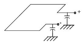
Figure A-6 shows a balanced inductive loop with the current flow from positive to negative and the balanced capacitances shown applying to the entry and exiting ends of the loop wire.

Figure A-6. Balanced inductive loop.

Because of the balanced configuration and zero potential point at the conductor perimeter center,

Equation A-14. C subscript 1 equals C subscript 2, which equals the product of the quotient of C prime times P over 6, times the quotient of P over 2, which equals the quotient of the numerator C prime times P all over 6. (A-14)

Thus

Equation A-15. C subscript L superscript E equals the quotient of the numerator C prime times P all over 3. (A-15)

where C1||C2 denotes the parallel connection of C1 and C2.

If only one side of the loop is grounded, then

Equation A-16. C subscript L super E equals the quotient of the numerator C prime times P all over 3. (A-16)

LOOP RESISTANCE THEORY

LOOP RESISTANCE

The series loop resistance RL is composed of the direct-current wire resistance R, the high-frequency skin-effect resistance Rac, and the ground resistance Rg. The dominant resistance is the ground resistance, which is caused by currents induced in the conductive pavement and subgrade material. The ground resistance may limit loop sensitivity in locations with large moisture content. Ground resistance is calculated by assuming that the pavement and subgrade materials cause a magnetic loss similar to that of a ferrite or iron core in an inductor. The permeability µg of the pavement and subgrade material is assumed to be one. Appendix A-1, of this Appendix A, contains a derivation of the ground resistance.

The series loop resistance RL is expressed as

Equation A-17. R subscript L equals R plus R subscript AC plus R subscript G. (A-17)
where  
 R = direct-current loop resistance (Ω)
 Rac = skin-effect resistance (Ω)
 Rg = ground resistance (Ω)
Equation A-18. R subscript G equals the tangent of delta G times omega times L subscript L. (A-18)
       tanδg = loss tangent of pavement material
 LL = loop self-inductance (H)
 ω = operating radian frequency = 2Πf (radians)
 f = operating frequency (Hz).

INTERNAL INDUCTANCE AND RESISTANCE PER UNIT LENGTH FOR A CYLINDRICAL CONDUCTOR

Johnson shows that the ratio of actual internal inductance to low-frequency internal inductance and the ratio of internal resistance to low-frequency internal resistance are given by(12)

Equation A-19. L subscript I divided by L subscript I0 equals 4 over Q times the quantity of the product in the numerator of the imaginary part of the complex Bessel function of the first kind of Q times the first derivative of the imaginary part of the complex Bessel function of the first kind of Q plus the product of the real part of the complex Bessel function of the first kind of Q times the first derivative of the real part of the complex Bessel function of the first kind of Q, all over the quantity third square of the first derivative of the imaginary part of the complex Bessel function of the first kind of Q plus the square of the real part of the complex Bessel function of the first kind of Q. (A-19)

and

Equation A-20. R divided by R subscript I0 equals Q over 2 times the quantity Of the product in the numerator of real part of the complex Bessel function of the first kind of Q times first derivative of the imaginary part of the complex Bessel function of the first kind of Q minus the imaginary part of the complex Bessel function of the first kind of Q times the first derivative of the real part of the complex Bessel function of the first kind of Q, all over the quantity third square of the first derivative of the imaginary part of the complex Bessel function of the first kind of Q plus the square of the real part of the complex Bessel function of the first kind of Q. (A-20)

Note: ber(q) is the real part of the complex Bessel function of the first kind. ber’(q) is the first derivative of the real part of the complex Bessel function of the first kind. bei(q) is the imaginary part of the complex Bessel function of the first kind. bei’(q) is first derivative of the imaginary part of the complex Bessel function of the first kind.

respectively, where

Equation A-21. Q equals the quotient of the product of alpha times the square root of 2 all over delta. (A-21)
 Li = internal inductance (H/m)
 a = radius of wire (m)
 δ = skin depth (m),
Equation A-22. Delta equals 1 over the square root of the product of mu subscript R, mu subscript 0, pi, F, and sigma. (A-22)
 µ0 = permeability of free space = 4Π x 10–7 H/m
 µr = relative permeability of copper wire = 1
 f = operating frequency (Hz)
 σ = conductivity of copper wire = 0.58 x 10⁸ mhos/m
 Li0 = low-frequency internal inductance (H/m),
Equation A-23. L subscript I0 equals the product of the quotient of the product of mu subscript 0 and mu subscript R, all over the product of 8 times pi, all times H over m. (A-23)
  = 0.5 x 10⁻⁷ H/m for copper wire
 Ri0= low-frequency internal resistance (Ω),
Equation A-24. R subscrip I0 equals the product of the quotient of rho subscript R divided by the product of pi times alpha squared, all multiplied by omega. (A-24)
ρr = resistivity (ohm-meter = Ωm)
     = 1.74 x 10⁻⁸ Ωm for copper wire.

LOOP-INDUCTANCE THEORY

SELF-INDUCTANCE OF SINGLE-TURN CIRCULAR LOOP

The self-inductance L0 of a single-turn circular loop is given by(14)

Equation A-25. L subscript 0 equals the product of mu subscript R, mu subscript 0, the quantity of the product of 2 and r, all minus a, all times the quantity of the difference of the product of the difference of 1 minus the quotient of k squared over 2, times capital K as a function of K, minus capital E as a function of K. (A-25)

where

Equation A-26. k squared equals the quotient of the product of 4, r, and the quantity r minus A, all over the squared quantity of the product of 2 and r, minus A. (A-26)
 E(k)= complete elliptic integral of first kind
 K(k)= complete elliptic integral of second kind
 r= radius of the loop coil relative to an axis normal to the plane of the loop that passes through the center of the loop (m)
 a= radius of the loop wire (m).

Therefore, the radius from the axis to the inside edge of the loop wire is r – a. The formula for E(k) is found in Appendix A-3 of this Appendix A.(15)

SELF-INDUCTANCE OF MULTITURN CIRCULAR LOOP

Following King(17), the inductance for a circular coil with N equally spaced identical turns is given by

Equation A-27. L subscript T equals N times L subscript 0 plus 2 times the quantity capital N minus 1, times capital M subscript 12, plus 2 times the quantity capital N minus 2 end quantity, times M subscript 13. (A-27)

or

Equation A-28. Capital L subscript capital T is equal to capital N times capital L nought plus 2 times summation from I equals 1 to capital N of the product of the difference between capital N and 1 times capital M subscript 1 comma I plus 1. (A-28)

where M1,(i+1) is the mutual inductance between turn 1 and turn i+1. According to Ramo,(18)

Equation A-29. Capital M is equal to mu subscript R times mu nought times square root of the product of R subscript 1 times R subscript 2, all multiplied by the difference between the product of the difference of the quotient of 2 over K minus k times capital K as a function of K minus the quotient 2 over K times capital E as a function of K. (A-29)
Equation A-30. K squared is equal to the quotient of the product of 4 times R subscript 1 times R subscript 2 all over the sum of D squared plus the quantity R subscript 1 plus R subscript 2 end quantity squared. (A-30)
where  
 M= mutual inductance (H)
 r1= radius of turn one (m)
 r2= radius of turn two (m)
 d= spacing between turns (m).

EXTERNAL INDUCTANCE OF SINGLE-TURN RECTANGULAR LOOP

The external inductance of a single-turn rectangular loop is given by the sum of the inductance of two pairs of conductors. Thus

Equation A-31. Capital L nought superscript E is equal to capital L subscript P1 superscript E plus capital L subscript P2 superscript E. (A-31)

The external inductance of a single turn rectangular loop is(1)
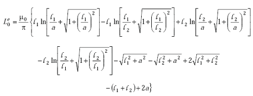
Equation A-32. Capital L nought superscript E is equal to the quotient mu nought over pi times the sum of 5 parts. Part 1 is L subscript 1 times the natural log of the sum of the quotient of L subscript 1 over A plus the square root of the sum of 1 plus the quantity L subscript 1 over A end quantity squared. Part 2 is negative L subscript 1 times the natural log of the sum of the quotient L subscript 1 over L subscript 2 plus the square root of the sum of 1 plus the quantity L subscript 1 over L subscript 2 end quantity squared. Part 3 is L subscript 2 times the natural log of the sum of the quotient L subscript 2 over A plus the square root of 1 plus the quantity L subscript 2 over A end quantity squared. Part 4 is negative L subscript 2 times the natural log of the sum of the quotient L subscript 2 over L subscript 1 plus the square root of 1 plus the quantity L subscript 2 over L subscript 1 end quantity squared. Part 5 is negative square root of the sum of L subscript 1 squared and A squared, minus the square root of the sum of L subscript 2 squared and A squared, plus 2 times the square root of the sum of L subscript 1 squared and L subscript 2 squared, minus the sum of L subscript 1 and L subscript 2 plus 2 times A. (A-32)
where  
 l1= width of loop (m)
 l2= length of loop (m)
 a= radius of the conductor (m).

This equation can be written in more compact form by combining the logarithmic terms.

SELF-INDUCTANCE OF SINGLE-TURN RECTANGULAR LOOP

The self-inductance of a single-turn rectangular loop is given by the sum of internal and external inductances as

Equation A-33. Capital L nought is equal to capital L nought superscript I plus capital L nought superscript E. (A-33)
Equation A-34. Capital L nought superscript I is equal to 2 times the sum of L subscript 1 and L subscript 2 all times capital L superscript I. (A-34)

where Li is given by Equation A-19 and Le0 is given by Equation A-32.

SELF-INDUCTANCE OF MULTITURN RECTANGULAR LOOP

The self-inductance of a coil with N equally spaced identical turns is given by

Equation A-35. Capital L subscript capital T equals capital N times capital L nought plus the product of 2 times the difference between capital N and 1, multiplied by capital M subscript 12 plus the product of two times the difference between capital N and 2, multiplied by capital M subscript 13 plus repeat the terms incrementing the N by negative 1 each successive capital M value. (A-35)

MUTUAL INDUCTANCE OF PARALLEL FILAMENTARY CIRCUITS

The mutual inductance between a pair of filamentary circuits located in free space and illustrated in Figure A-7 is given by(19)

Equation A-36. Capital M is a function of L and D and is equal to the plus or minus value of the quotient of the product mu nought and L over 2 pi all times the sum of the natural log of the quotient L over D plus the square root of 1 plus the quantity L over D end quantity squared, minus 1, plus the square root of the sum of the quantity D over L end quantity squared plus the quotient D over L. (A-36)
where  
 µ0= permeability of free space = 4Π x 10–7 H/m
 l= filamentary length (m)
 d= filamentary spacing (m)
 M(l,d)= mutual inductance (H).

The mutual inductance is positive when the current flow in the filaments is in the same direction and negative when the current flow is in opposite directions.
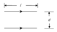
Figure A-7 shows that the geometry of two parallel filaments of loop wire may be described by the distance between the filaments called D and the length of the two filaments called L.

Figure A-7. Pair of parallel current elements.

MUTUAL INDUCTANCE OF TWO COAXIAL AND PARALLEL RECTANGULAR LOOPS

Equation A-36 can be used to calculate the total mutual inductance of the coaxial and parallel rectangular loops displayed in Figure A-8.
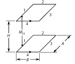
Figure A-8 shows that loop turn geometry is concerned with the spacing H between the corresponding sides of the loop where the sides are numbered 1, 2, 3, and 4. Since the nonparallel sides of a rectangular loop may not be the same length, they are labeled A and B respectively. The mathematical relationships of the mutual inductance of this geometry are presented in equation 36.

Figure A-8. Geometry for calculating mutual inductance of coaxial and parallel rectangular loops.

Accordingly, the total mutual inductance is given by the sum of the mutual inductances between the parallel sides as

Equation A-37. Capital M is equal to negative 2 times the sum of M subscript 13 which is a function of capital A and the square root of the sum of capital H squared and capital B squared, minus capital M subscript 11 which is a function of capital A and capital H, plus capital M subscript 24 which is a function of capital B and the square root of the sum of capital H squared plus capital B subscript 2, minus capital M subscript 22 which is a function of capital B and capital H. (A-37)

where M11 is the mutual inductance between side 1 of the bottom loop turn and side 1 of the top loop turn. All mutual inductances are symmetrical, e.g., M13 = M31 and M24 = M42.

SELF-INDUCTANCE OF MULTITURN QUADRUPOLE LOOP

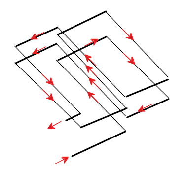
Figure A-9 illustrates a two-turn quadrupole loop(20) and Figure A-10 a multiturn quadrupole loop.

The external inductance of an N-turn quadrupole loop is

Equation A-38. Capital L subscript capital T is equal to the product of 2 ,capital N, and capital L nought plus the product of 2, capital N, and capital M subscript 12, plus the product of 4, the difference between capital N and 1, and capital M subscript 13, plus the product of 4, the difference between capital N and 1, and capital M subscript 14, plus the product of 4, the difference between capital N and 2, and capital M subscript 15, plus the product of 4, the difference between capital N and 2, and capital M subscript 16 ... (A-38)
FIGURE A-9.	TWO TURN QUADRUPOLE LOOP. Use and design quadrupole loops are discussed in sChapter 4. The figure shows that the loop is wired in the shape of a figure 8 with the wires in the middle of the 8 all going in the same direction to enhance sensitivity to detecting small vehicles.

Figure A-9. Two-turn quadrupole loop.
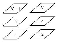
Figure A-10 shows that the two halves of a quadrupole loop may be represented as a stack of rectangles with the number of elements in each stack determined by the number of turns of wire in the loop.

Figure A-10. Multiturn quadrupole loop.

GENERAL FORMULA FOR MUTUAL INDUCTANCE OF PARALLEL FILAMENTS

In order to calculate the mutual inductance between the offset loops in the quadrupole loop model, a general formula for the mutual inductance of parallel, offset filaments is required. In Figure A-11, these filaments are labeled Segment i and Segment k.

Following Jefimenko(21), the mutual inductance between the two parallel current filaments illustrated in Figure A-11 is given by

Equation A-39. Capital M subscript I K is equal to the plus or minus value of the quotient mu nought over 4 pi times the sum of the natural log of the quotient of the product of the sum A and capital A to the A power times the sum of B and capital B to the B power all over the product of the sum of C plus capital C to the C power times the sum of D plus capital D to the D power, plus capital D plus capital C minus the sum of capital B and capital A all evaluated over I K. (A-39)

where the positive sign is used for filaments with current flow in the same direction.

This expression assumes that the filament lengths are much less than the wavelength divided by 2p and the conductor radius is much less than the filament length. Grover(22) shows that this type of general formula can also be derived by applying the laws of summation of mutual inductance to Equation A-36.
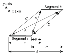
Figure A-11 shows that the geometry of the relationship between parallel line segments I and K in an X-Y coordinate field with the elements both parallel to the X axis may be represented C, the distance between the starting points of the two filaments; D, the distance between the ending points of the two filaments; A, the distance between the start of segment I and the end of segment K; and B, the distance between the end of segment I and the beginning of segment K. Also relevant is small C, the distance along the X axis between the start of segment I and the start of segment K, and small D, the distance along the X axis between the end of segment I and segment K. Small B represents the distance along the X axis between the end of segment I and the beginning of segment K, while small A represents the distance along the X axis from the beginning of segment I and the end of segment K. Thus, all the capitalized variables are the distances in the X-Y plane while all the small variables of the same letter are the X component of that distance.

Figure A-11. Mutual inductance of two parallel segments i and k.

INDUCTIVE-LOOP CIRCUIT MODEL

Figure A-12 illustrates an inductive-loop system electrical circuit model that contains resistive, capacitive, and inductive components.
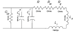
Figure A-12 shows that an inductive loop circuit may be modeled as an inductance G sub small CP in parallel with a capacitance C sub L super small E and a capacitance C sub L super 1. All of these are in parallel with a series of resistors and inductances with the resistors labeled R, R sub small AC, R sub small G, and the inductances L sub O and L sub small I.

Figure A-12. Inductive-loop system circuit model.

Let

Equation A-40. Capital L subscript capital S is equal to capital L nought plus capital L subscript I. (A-40)
Equation A-41. Capital R subscript capital S is equal to capital R plus capital R subscript G. (A-41)
Equation A-42. Capital C subscript capital P is equal to capital C subscript capital L superscript I plus capital C subscript capital L superscript E. (A-42)

Following Johnson,(23) the slot dielectric loss conductance is

Equation A-43. Capital G subscript P is equal to the product of omega, capital C subscript capital P, and tangent of delta subscript C. (A-43)

where tanδc is the loss tangent of the slot sealer material.

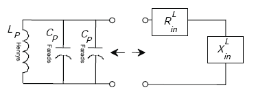
Appendix A-4, of this Appendix A, shows that the inductive-loop system circuit model of Figure A-12 reduces to the circuit model of Figure A-13,

where
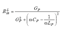
Equation A-44. Capital R subscript I N superscript capital L is equal to the quotient of capital G subscript capital P all over the sum of capital G subscript capital P squared plus the quantity omega times capital C subscript capital P minus 1 over the product of omega times capital L subscript capital P end quantity squared. (A-44)

and

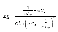
Equation A-45. Capital X subscript I N superscript capital L is equal to the quotient of the sum of the quotient 1 over the product of omega and capital L subscript capital P minus the product of omega and capital C sub subscript capital P all over the sum of capital G subscript capital P squared plus the quantity omega times capital C subscript capital P minus 1 over the product of omega times capital L subscript capital P end quantity squared. (A-45)

The loop quality factor is given by

Equation A-46. Capital Q subscript I N superscript L is equal to the quotient capital X subscript I N superscript capital L over capital R subscript I N superscript capital L. This is equal to the quotient of the quotient 1 over the product of omega and capital L subscript capital P minus the product of omega and capital C subscript capital P all over capital G subscript capital P. (A-46)

The self-resonant frequency of the loop is given by

Equation A-47. F nought is equal to 1 over 2 pi times the square root of the product of capital L subscript capital P and capital C subscript capital P. (A-47)
Figure A-13 shows that the circuit of Figure 12 can be reduced to an equivalent circuit with an inductance L sub P in parallel with two capacitances C sub P and C sub P. This circuit in turn may be modeled as R sub small IN and X sub small IN as a series.

Figure A-13. Equivalent loop circuit model.

LOOP TRANSMISSION LINE THEORY

LOOP TRANSMISSION LINE MODEL

A transmission line connects the roadway loop with the roadside electronics unit. The complex impedance ZL of the loop is transformed to a complex impedance Zin by the transmission line cable according to(24)

Note:The ratio of current to voltage is defined as conductance G = i / v. The unit of conductance is the mho (for inverse ohms) and is denoted by an inverted capital omega.

Equation A-48. Capital Z subscript IN superscript C is equal to capital Z nought times the quotient of the sum of capital Z subscript capital L plus the product of capital Z nought times the hyperbolic tangent of the product of gamma and L all over the sum of capital Z nought plus the product of capital Z subscript capital L and the hyperbolic tangent of the product of gamma and L. (A-48)

where

Equation A-49. Capital Z subscript capital L is equal to capital R subscript capital L plus the product of j, omega, and capital L subscript capital L. (A-49)
Equation A-50. Capital Z nought is equal to the square root of the quotient of the sum capital R and the product of J, omega, and capital L all over the sum of capital G and the product of J, omega, and capital C. (A-50)
Equation A-51. Gamma is equal to the square root of the product of the sum of capital R plus the product of J, omega, and capital L times the sum of capital G plus the product of J, omega, and capital C. (A-51)
and where  
 R= transmission line per unit resistance (Ω/m)
 G= transmission line per unit conductance (mhos/m)
 L= transmission line per unit inductance (H/m)
 C= transmission line per unit capacitance (F/m)
 RL= loop equivalent resistance (Ω)
 LL= loop equivalent inductance (H)
 ω= radian frequency (radians)
 l= length of transmission line
 γ= complex propagation constant.

A useful equation for computing Zin is given by(25)

Equation A-52. The hyperbolic tangent of the quantity X plus or minus K times Y is equal to the quotient of the hyperbolic sine of 2 times X plus or minus J times the sine of 2 times Y all over the sum of the hyperbolic cosine of 2 times X plus the cosine of 2 times Y. (A-52)

FREQUENCY SHIFT ELECTRONICS UNIT SENSITIVITY

The frequency shift ΔfD at the terminals of the electronics unit is required to compute the sensitivity of the inductive-loop system as a function of loop and cable inductance.

Let

Equation A-53. F subscript capital V minus F subscript capital N capital V is equal to negative capital delta F subscript capital D. (A-53)

and

Equation A-54. F subscript capital N capital V is equal to F subscript capital D. (A-54)

where fV, fNV are the frequencies measured by the electronics unit with and without a vehicle present.

The sensitivity SD of the frequency shift electronics unit is defined as

Equation A-55. Capital delta F subscript capital D over F subscript D is equal to negative one half times capital S subscript capital D. (A-55)

The total inductance LD at the electronics unit is the sum of the loop and cable inductances given by

Equation A-56. Capital L subscript capital D is equal to capital L subscript capital L plus capital L subscript capital C. (A-56)

Therefore, the change in inductance created by a vehicle passing over the loop is

Equation A-57. Capital delta capital L subscript capital D is equal to capital delta capital L subscript capital L. (A-57)

since it is only the loop inductance that varies in the presence of a vehicle.

To convert the expression for sensitivity in terms of ΔfD/fD to one in terms of ΔLL/LL, note that

Equation A-58. F subscript D equals 1 divided by the quantity of the product 2 times pi times the square root of Capital L subscript Capital D times Capital C subscript Capital D, end quantity. (A-58)

Thus,

Equation A-59. Delta f subscript D divided by f subscript D equals negative one half times the quotient delta capital L subscript capital L, all over capital L subscript L plus capital L subscript C. (A-59)

By inspection,

Equation A-60. S subscript D equals the quotient of delta capital L subscript capital L all over capital L subscript capital L plus capital L subscript C. (A-60)

Therefore,

Equation A-61. Capital S subscript Capital D equals the product of the quotient of delta capital L subscript capital L over capital L subscript capital L, times the quotient of the numerator quotient of 1 over capital L subscript capital L plus capital L subscript capital C, all over capital L subscript capital L, which equals the product of the quotient of delta capital L subscript capital L over capital L subscript capital L, times the quotient of the numerator quotient of 1 all over the denominator of 1 plus the quotient capital L subscript capital C over L subscript capital L, which equals the product of capital S subscript L times the quotient of the numerator 1 all over the denominator of 1 plus the quotient of capital L subscript capital C over capital L subscript capital L. (A-61)

and Equation A-55 becomes

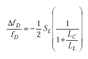
Equation A-62. Delta f subscript capital D divided by f subscript capital D equals negative one half times Capital S subscript capital L times the quotient of the numerator of 1 all over the denominator of 1 plus the quotient of capital L subscript capital C over capital L subscript capital L. (A-62)

where

Equation A-63. Capital S subscript capital L equals delta Capital L divided by Capital L. (A-63)

Equation A-62 shows that the cable inductance LC strongly affects the sensitivity of the frequency shift electronics unit. If the cable inductance is one-tenth or less of the loop inductance, the cable has a negligible effect on inductive-loop system sensitivity, provided the quality factor QD is five or greater. The frequency shift electronics unit sensitivity results also apply to period shift electronics units.

LOOP TRANSFORMER THEORY

INDUCTIVE-LOOP TRANSFORMER MODEL

A transformer with low leakage inductance (e.g., total series leakage inductance less than transmission line inductance) can be placed between the loop and transmission line to transform the loop inductance to a value larger than the transmission line inductance.(26) The transformer will remove the reduction in sensitivity caused by the transmission line.

The transformer model is shown in Figure A-14.(27)
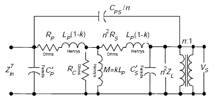
Figure A-14 shows that the modified primary capacitance C sub P across Z sub small IN is determined with C sub PS over N in parallel with series of R sub P and L sub P, the resistance corresponding to the core loss R sub C and the inductance small K capital L sub P and the series of L sub P and the inductance small N squared R sub S and the parallel of C prime sub small S and N squared capital Z sub capital L and the voltage drop V sub S.

Figure A-14. Loop transformer model.

The definitions of the parameters that appear in Figure A-14 are referred to the primary of the transformer. Thus,

 RP= primary winding resistance
 RC= resistance corresponding to core loss
 n2RS= referred secondary winding resistance
 n2ZL= referred load impedance
 CP= primary capacitance
 CS= secondary capacitance
 CS'= modified secondary shunting capacitance,
Equation A-64. C prime subscript S equals the sum of the quotient of C subscript S divided by n squared, plus the product of the quotient of the numerator capital C subscript capital P S over N, times the quantity of the quotient of 1 over n, minus 1, end quantity. (A-64)
 CPS/n= referred primary to secondary capacitance
 CP'= modified primary capacitance,
Equation A-65. C prime subscript capital P equals C subscript capital P plus the product of C subscript capital P S times the quantity of 1 minus the quotient of 1 over n, end quantity. (A-65)
 n= ratio of primary to secondary turns,
Equation A-66. Small N equals square root capital L subscript capital P end square root, divided by square root of capital L subscript capital S end square root. (A-66)
 LP= open circuit primary inductance at low frequency
 LP (1–K)= one-half total leakage inductance
 K= coupling coefficient,
Equation A-67. K equals capital M over the square root of the product of capital L subscript capital P and capital L subscript capital S. (A-67)
 M= mutual inductance.

The equivalent transformer model of Figure A-15 was used to derive an expression for the transformed load impedance ZinT.
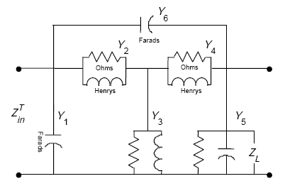
FIGURE A-15.	EQUIVALENT TRANSFORMER MODEL. The equivalent transformer model is the capacitance of Y sub 6 in parallel with Y sub 2 and Y sub 4 in series and Y sub 1, Y sub 3, and Y sub 5 in parallel.

Figure A-15. Equivalent transformer model.

Appendix A-5, of this Appendix A, shows that the transformed load impedance is given by

Equation A-68. Capital Z subscript I N superscript capital T equals the quotient of the numerator of the absolute value of the product of the quantity of capital Y subscript 2 plus capital Y subscript 3 plus capital Y subscript 4 end quantity, times the quantity capital Y subscript 4 plus capital Y subscript 5 plus capital Y subscript 6 end quantity, all minus capital Y subscript 4 superscript 2, all over the denominator of the quantity of capital Y subscript 1 plus capital Y subscript 2 plus capital Y subscript 3 end quantity, times the quantity of the product of the quantity of capital Y subscript 2 plus capital Y subscript 3 plus capital Y subscript 4 end quantity, times the quantity of capital Y subscript 4 plus capital Y subscript 5 plus capital Y subscript 6 end quantity, all minus capital Y subscript 4 superscript 2, end product, minus the product of 2, capital Y subscript 2, capital Y subscript 4, and capital Y subscript 6, minus the product of capital Y subscript 6 superscript 2 times the quantity of capital Y subscript 2 plus capital Y subscript 3 plus capital Y subscript 4 end quantity, all minus the product of capital Y subscript 2 superscript 2 times the quantity capital Y subscript 4 plus capital Y subscript 5 plus capital Y subscript 6 end quantity. (A-68)

LOOP-DETECTOR ANALYSIS SYSTEM PROGRAM

The loop-detector analysis system (LDAS) computer program calculates loop inductance and quality factor for rectangular, quadrupole, and circular loops. The loop inductance and quality factor are transformed by the transmission line (nonshielded, twisted-loop wire) to the roadside junction box and transmission line (shielded, twisted pair) between the junction box and electronics unit in the controller box. The program also models a transformer between the loop and transmission line or between the two types of transmission lines.

The LDAS program is menu driven and written in Microsoft QuickBasic. All mathematical functions are computed using double precision calculations.

COMPARISON OF CALCULATED AND MEASURED LOOP SELF-INDUCTANCE AND QUALITY FACTOR

Table A-1 contains measured self-inductance and quality factor data for a 6- x 6-ft (1.8- x 1.8-m) three-turn inductive loop. The measured and LDAS computed data compare favorably as shown in Table A-2. Measured loop inductance and quality factor data versus frequency were unavailable for quadrupole and circular loops.

Table A-1. Measured inductive-loop parameters of 3-turn 6- x 6-ft (1.8- x 1.8-m) loop with no vehicle present.
f0 (kH z )f2 3dB (kHz)f1 3dB(kHz)Q=f0/f2-f1C (µF)L=1/(2πf0)2C (µH)R=2Πf0L/Q (Ω)
20 20.33419.70231.70.85649073.90.29
25 25.37224.68835.50.54810973.90.33
30 30.38829.64440.30.38000074.10.35
35 35.42734.60742.70.27869374.20.38
40 40.47039.57344.60.21205674.30.42
45 45.51449.47245.70.16788774.50.46
50 50.57149.47245.50.13570474.70.52
55 55.63354.40744.90.11184574.90.58
60 60.70459.34244.10.09345075.30.64
Loop size:6 ft x 6 ft (1.83 m x 1.83 m)
Loop number of turns: 3
Loop wire size: #14 AWG
Loop lead-in length: 60 in (1.5 m)
Loop self-resonant frequency: 697.06 kHz
50 pF residual capacitance in decade box neglected in C value 
 
Table A-2. Comparison of measured and computed inductive-loop parameters of 3-turn 6- x 6-ft (1.8- x 1.8-m) loop with no vehicle present.
f0 (kHz)Measured L (µH)Calculated L (µH)Measured QCalculated Q
20 73.974.431.730.4
25 73.974.435.533.9
30 74.174.340.336.6
35 74.274.342.738.8
40 74.374.344.640.6
45 74.574.345.742.2
50 74.774.345.543.7
55 74.974.344.944.9
60 75.374.344.146.1
Calculated loop parameters are based on:
  • Loop size: 6 ft x 6 ft (1.83 m x 1.83 m)
  • Pavement loop slot width: 375 mils (0.95 cm)
  • Loop slot sealant dielectric constant: 6
  • Pavement material loss tangent: 0.01
  • Loop wire insulation dielectric constant: 2.5
  • Effective loop wire insulation loss tangent: 0.001
  • Loop conductor spacing: 200 mils (0.51 cm)
  • Wire gauge: #14 AWG

Tables A-3 through A-5 list calculated loop inductance and quality factor as a function of conductor size. The quality factor decreases with increasing wire gauge as expected. The addition of a transmission line of 240-ft (73.2-m) length approximately halves the quality factor. Inductive-loop detector applications requiring transmission lines over 200 ft (61 m) in length should use number #12 AWG wire for the loop and nonshielded transmission line. Three to four turns of loop wire have an adequate quality factor. One to two turn loops should be used with a transformer.

Table A-3. Rectangular-loop parameters.
Wire gauge (AWG) 1-Turn inductance µH)1-Turn quality factor2-Turn inductance(µH)2-Turn quality factor3-Turn inductance(µH)3-Turn quality factor4-Turn inductance(µH)4-Turn quality factor5-Turn inductance(µH)5-Turn quality factor
12 10.1319.6835.2229.8873.2837.13123.1442.65184.0047.03
14 10.5015.6135.9624.0674.3930.40124.6235.41185.8539.51
14* 63.4511.5989.1614.11128.1817.51179.6121.20242.9624.86
14** 351.701.77853.204.901433.699.991985.5117.242464.1626.76
16 10.8511.5736.6818.1075.4623.25126.0427.50187.6231.09
18 11.208.1137.3712.8476.5016.73127.4220.05189.3922.95
*  Transmission line
** Transformer loop
    Notes:
  1. 20 kHz; loop size:6 ft x 6 ft (1.83 m x 1.83 m); other parameters are the same as those given for Table A-2.
  2. All inductance and quality factors in Table A-3 are apparent values (i.e., the effect of loop capacitance and resistance is included).
  3. Transformer parameters:
    • Primary resistance (ohms) = 1
    • Primary capacitance (picofarads) = 10
    • Primary inductance (millihenrys) = 5
    • Secondary resistance (ohms) = 1
    • Secondary capacitance (picofarads) = 10
    • Primary to secondary turns ratio = 5
    • Core loss resistance (ohms) = 1,000,000
    • Coupling coefficient = 0.99
    • Primary to secondary capacitance (picofarads) = 10
  4. Transmission line parameters
    • Length = 240 ft (73.2 m)
    • Resistance (milliohms/ft) = 2.5 (6.25 milliohms/m)
    • Inductance (microhenrys/ft) = 0.22 (0,72 microhenrys/m)
    • Conductance (microohms/ft) = 0.000076 (0.000249 microohms/m)
    • Capacitance (picofarads/ft) = 26 (85.3 picofarads/m)
Table A-4. Quadrupole-loop parameters.
Wire
gauge (AWG)
1-Turn inductance
(µH)
1-Turn quality
factor
2-Turn inductance
(µH)
2-Turn
quality factor
3-Turn inductance
(µH)
3-Turn
quality factor
4-Turn inductance
(µH)
4-Turn
quality factor
5-Turn inductance
(µH)
5-Turn
quality factor
12 17.1421.7260.1532.74125.4240.32210.7845.93314.7750.27
14 17.6917.2661.2626.53127.0833.28212.9838.48317.4942.64
16 18.2212.8162.3220.07128.6725.67215.0930.18320.1033.91
18 18.748.9963.3614.32130.2218.61217.1522.21322.6525.29
Notes:
  1. 20 kHz; loop size:6 ft x 6 ft (1.83 m x 1.83 m); lateral conductor spacing: 200 mils (0.51 cm), other parameters are the same as those given for Table A-2.
  2. All inductance and quality factor values in Table A-4 are apparent values (i.e., the effect of loop capacitance and resistance is included).
Table A-5. Circular-loop parameters.
Wire gauge (AWG)1-Turn inductance µH)1-Turn quality factor2-Turn inductance(µH)2-Turn quality factor3-Turn inductance(µH)3-Turn quality factor4-Turn inductance(µH)4-Turn quality factor5-Turn inductance(µH)5-Turn quality factor
12 9.7020.3933.9530.9570.9138.42119.5044.07179.0048.53
14 10.0416.1934.6324.9871.9331.55120.8636.73180.6940.95
16 10.3712.0035.2918.8372.9124.21122.1628.63182.3132.36
18 10.688.4235.9213.3873.86 17.47123.4320.96183.8924.00
Notes:
  1. 20 kHz; loop diameter: 7 feet (2.1 m); other parameters are the same as those given for Table A-2.
  2. All inductance and quality factor values in Table A-5 are apparent values (i.e., the effect of loop capacitance and resistance is included).

CONCLUSIONS

Loop inductance should be measured at 1 kHz to remove effects of capacitance when determining the number of turns in a buried loop. All loop measurements at frequencies of 20 kHz or greater should be made with a balanced instrument since the loop electronics unit is balanced. An unbalanced measurement produces incorrect results because of the different capacitance-to-ground values. Since the external capacitance is determined by the dielectric constant of the slot sealing material, the loop wire should be completely sealed to prevent water from entering the loop slot. The large dielectric constant of water produces a significant change in the external capacitance and causes the apparent loop inductance to change. Thus, unstable loop operation can result from incomplete sealing of the loop sawcut.

APPENDIX A-1

LOOP GROUND-RESISTANCE DERIVATION

The complex impedance ZL of the loop results from a complex permeability µg, where µg represents a complex number. The complex impedance is given by

Equation A-69. Z subscript capital L equals the product of J times omega times mu subscript G times L subscript Capital L. (A-69)
Equation A-70. Factoring out J times omega in equation A-65, Z subscript capital L can be rewritten as equal to the product of J times omega times the quantity of mu prime subscript G minus the product of J times mu double prime subscript G end quantity, times capital L subscript capital L. (A-70)

The material loss tangent, denoted as tanδg, is given by

Equation A-71. Tangent small delta subscript G equals the quotient of mu double prime subscript G divided by mu prime subscript G. (A-71)

Letting µ'g = 1, the loss tangent becomes

Equation A-72. When mu prime subscript G equals 1, then Tangent small delta subscript G equals mu double prime subscript G. (A-72)

Then

Equation A-73. Capital Z subscript capital L equals the product of J times omega times the quantity one minus the product of J times tangent delta subscript G end quantity, times capital L subscript capital L. (A-73)
Equation A-74. Capital Z subscript capital L equals the sum of the product of omega times tangent delta subscript G, times capital L subscript capital L, plus the product of J times omega times capital L subscript capital L. (A-74)

When the complex impedance is written in the form

Equation A-75. Capital Z subscript capital L equals Capital R subscript G plus the product J times capital X subscript capital L. (A-75)

the real and imaginary parts of ZL become

Equation A-76a. Capital R subscript G equals the product of tangent delta G end tangent times omega times capital L subscript capital L. (A-76a)

and

Equation A-76b. Capital X subscript capital L equals the product of omega times capital L subscript capital L. (A-76b)

where Rg is the material ground loss and XL is the inductive reactance.

APPENDIX A-2

REAL PART OF COMPLEX BESSEL FUNCTION OF FIRST KIND

Equation A-77. Real Part of Bessel Function of X equals one minus the quotient of the numerator of the quotient of the quantity of one half X end quantity raised to the fourth power, all over the denominator squared factorial of 2 plus the quotient of the numerator of the quotient of the quantity of one half X end quantity raised to the eighth power, all over the denominator squared factorial of 4, etc…. (A-77)

or

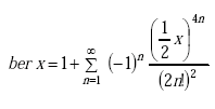
Equation A-78. Real Part of Bessel Function of X equals one plus summation from n equals 1 to N equals infinity of minus 1 to the N power, all times the quotient of the numerator of one-half X raised to the 4 times N power, all over the denominator of the squared quantity of 2 times the factorial of N. (A-78)

DERIVATIVE OF REAL PART

Equation A-79. First derivative Real Part of Bessel Function of X equals fraction first negative 0.5 times X raised to the third power divided by one factorial times two factorial end fraction first plus fraction second 0.5 times X raised to the seventh power divided by 3 factorial times 4 factorial end fraction second times fraction third 0.5 times X raised to the eleventh power divided by five factorial times six factorial end fraction third plus . . . et cetera. (A-79)

or

Equation A-80. First derivative Real Part of Bessel Function of X equals summation from N equals 1 to N equals infinity of minus 1 to the N power, all times the quotient of the numerator of one half X raised to the power of the quantity of the product of 4 and X, minus 1, all over the denominator of the product of the factorial quantity of the product of 2 and N minus 1, times 2 times N factorial. (A-80)

IMAGINARY PART OF COMPLEX BESSEL FUNCTION OF FIRST KIND

Equation A-81. Ber imaginary x equals fraction first 0.5 times X raised to the second power divided by one factorial to the second power end fraction first minus fraction second 0.5 times X raised to the sixth power divided by 3 factorial to the second power end fraction second times fraction third 0.5 times X raised to the tenth power divided by five factorial to the second power end fraction third minus . . . et cetera. (A-81)

or

Equation A-82. Imaginary Part of complex Bessel Function of x equals summation from N equals 1 to N equals infinity of the negative of the quantity of negative 1 raised to the power of N, all times the quotient of the numerator of one half X raised to the power of the quantity of the product of 4 and X, minus 2, all over the denominator of the squared factorial of the quantity of the product of 2 and N, minus 1. (A-82)

DERIVATIVE OF IMAGINARY PART

Equation A-83. Derivative of Imaginary Part of complex Bessel Function of X equals fraction first 0.5 times x end fraction first minus fraction second 0.5 times X raised to the fifth power divided by 2 factorial times 3 factorial end fraction second times fraction third 0.5 times X raised to the ninth power divided by four factorial times five factorial end fraction third minus . . . et cetera. (A-83)

or

Equation A-84. Derivative of Imaginary Part of complex Bessel Function of x equals summation from N equals 1 to N equals 1 to N equals infinity of the negative of the quantity of negative 1 raised to the power of N, all times the quotient of the numerator of one half X raised to the power of the quantity of the product of 4 and X, minus 3, all over the denominator of the product of the factorial of the quantity of the product of 2 and N, minus 2, times the factorial quantity of the product of 2 and N, minus 1. (A-84)

APPENDIX A-3

COMPLETE ELLIPTIC INTEGRAL OF FIRST KIND

Equation A-85. Capital K as a function of small K equals 0.5 pi times pi product summation from M equals 0 to M equals infinity of the quantity 1 plus small K subscript M plus 1. (A-85)
Equation A-86. Small K subscript M plus 1 equals the quotient of the numerator of the quantity 1 minus small K subscript small M prime, all over the denominator of the quantity 1 plus small K subscript small M prime. (A-86)
Equation A-87. Small K subscript M prime equals the square root of the quantity one minus small K squared subscript small M . (A-87)
Equation A-88. Small K nought equals small K. (A-88)

COMPLETE ELLIPTIC INTEGRAL OF SECOND KIND

Equation A-89. Capital E as a function of K equals the product of the quantity of pi divided by 2 times the quantity of 1 minus K, all times the quantity of 1 plus the quotient of K squared over 2 squared, plus the product of the quotient of 1 squared over the product of 2 squared and 4 squared, times K raised to the power of 4, plus the product of the quotient of the numerator of the product of 1 squared and 3 squared, all over the denominator of the product of 2 squared, 4 squared, and 6 squared, all times K raised to the power of 6, etc. (A-89)

or

Equation A-90. Capital E as a function of small K equals the product of the quotient of pi over 2 times the quantity 1 minus K, all times the quantity of 1 plus the product of K raised to the power of 2 times N, all times the summation from N equals 1 to infinity of the squared quotient of the numerator of the double factorial of the quantity of 2 times N, minus 3, all over the denominator double factorial of 2 times N. (A-90)
Equation A-91. Small K equals the quotient of the numerator 1 minus small K prime all over the denominator 1 plus small K prime. (A-91)
Equation A-92. Small K prime equals the square root of the quantity one minus M. (A-92)
Equation A-93. Capital M equals small K squared. (A-93)

where 2N!! = 2NN!.

APPENDIX A-4

SERIES TO PARALLEL CIRCUIT TRANSFORMATION

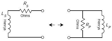
Figure A-16 shows that the series of L sub S and R sub S may be represented as the parallel circuit of R sub P and L sub P. The equivalent relationships of the Z sub small IN of the two circuits are described in equations 90 through 93.

Figure A-16. Series-circuit to parallel-circuit equivalency (general).

From Figure A-16,

Equation A-94. Capital Z subscript I N equals Capital R subscript G plus J times omega times capital L sub S and Capital Y sub I N equals (1 divided by Capital R sub p) minus j times 1 divided by omega times capital L subscript capital S; and capital Y subscript I N equals the quotient of 1 over capital R subscript P minus the product of J and the quotient of 1 over the product of omega and capital L subscript P. (A-94)

setting

Equation A-95. 1 divided by Capital Z subscript I N equals Capital Y subscript I N. (A-95)

we find

Equation A-96. Capital R subscript capital P equals the quotient of the numerator Capital R subscript capital S squared plus omega squared times capital L subscript capital S squared, all over the denominator Capital R subscript capital S. (A-96)

and

Equation A-97. Capital L subscript capital P equals the quotient of the numerator Capital R subscript capital S squared plus omega squared times capital L subscript capital S squared, all over the denominator omega squared times capital L subscript capital S. (A-97)
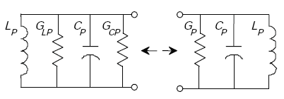
FIGURE A-17. LOOP SERIES TO PARALLEL CIRCUIT EQUIVALENCY. If the parallel circuit consists of G sub P, C sub P, and L sub P then it may be represented as the parallel of L sub P, G sub LP, C sub P and G sub CP, as explained in equations 94, 95, and 96.

Figure A-17. Loop-series to parallel-circuit equivalency.

From Figure A-17,

Equation A-98. Capital G subscript capital P equals Capital G subscript L P plus Capital G subscript C P. (A-98)
Equation A-99. Capital Y subscript I N superscript L equals Capital G subscript capital P plus the product of J times the quantity of the product of omega and capital C subscript capital P, all minus the quotient of 1 over the product of omega and capital L subscript capital P, end quantity. (A-99)
Equation A-100. Capital Y subscript I N superscript capital L equals 1 divided by Capital Z subscript I N. (A-100)

APPENDIX A-5

TRANSFORMER MODEL INPUT IMPEDANCE

The transformed load impedance shown in equation A-68 is derived from nodal analysis of the transformer model. The transfer function is defined as the ratio of the output of a system to the input. It is thus used to find the output of a system or module for a given input.
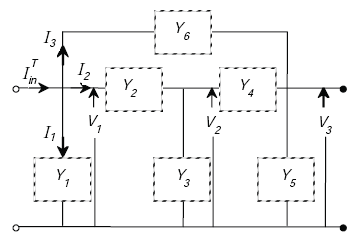
Figure A-18 shows an electrical engineering nodal analysis that the transformer model input impedance I in sub T equals equivalent transformer model is the capacitance of Y sub 6 in parallel with Y sub 2 and Y sub 4 in series and Y sub 1, Y sub 3, and Y sub 5 in parallel. The voltages across the system are V sub 1, V sub 2, and V sub 3, respectively.

Figure A-18. Transformer nodal analysis diagram.

From Figure A-18, we find

Equation A-101. First one Column Matrix with columns row elements of 1, 0, 0 set equal to a three column three row matrix times a one column matrix with the three column three row matrix, first column elements of Row 1 Capital Y subscript 1 plus Capital Y subscript 2 plus Capital Y subscript 6 Row 2 of negative Capital Y subscript 2 Row 3 of negative Capital Y subscript 6 With the second column being Row 1 of negative Capital Y subscript 2 Row 2 of Capital Y subscript 2 plus Capital Y subscript 3 plus Capital Y subscript 4 negative Capital Y subscript 4 With the third column being Row 1 of negative Capital Y subscript 6 Row 2 of negative Capital Y subscript 4 Row 3 of Capital Y subscript 4 plus Capital Y subscript 5 plus Capital Y subscript 6 This 3 colunm 3 row matrix is times a 3 row one column matrix with the row elements of Row 1 of Capital V subscript 1 Row 2 of Capital V subscript 2 Row 3 of Capital V subscript 3. (A-101)
Equation A-102. Capital I subscript I N superscript capital T equals Capital I subscript 1 plus Capital I subscript 2 plus Capital I subscript 3. (A-102)
Equation A-103. Capital I subscript I N superscript capital T equals capital Y subscript 1 times capital V subscript 1 plus capital Y subscript 6 times the quantity of capital V subscript 1 minus capital V subscript 3 end quantity, all plus capital Y subscript 2 times the quantity capital V subscript 1 minus capital V subscript 2 end quantity. (A-103)
Equation A-104. Capital Z subscript I N superscript capital T equals Capital V subscript 1 over Capital I subscript I N, which equals the quotient of 1 over the denominator Capital Y subscript 1 plus capital Y subscript 6 times the quantity Capital V subscript 1 minus the quotient of Capital V subscript 3 over capital V subscript 1 end quantity, plus Capital Y subscript 2 times the quantity Capital V subscript 1 minus the quotient of Capital V subscript 2 over capital V subscript 1. (A-104)
Equation A-105. First one Column three row Matrix set equal to the inverse of a three column three row matrix times a second one column matrix. This in turn is set equal to a second three column by three row matrix which is the inverse whose terms are the terms of the inverse of the first three row three column matrix times a third one column 3 row matrix. The first one column three row matrix has elements of Row 1 of Capital V subscript 1 Row 2 of Capital V subscript 2 Row 3 of Capital V subscript 3 with the first three column three row matrix first column elements of Row 1 of Capital Y subscript 11 Row 2 of Capital Y subscript 21 Row 3 of Capital Y subscript 31 With the second column being Row 1 of Capital Y subscript 12 Row 2 of Capital Y subscript 22 Row 3 of Capital Y subscript 32 With the third column being Row 1 of Capital Y subscript 13 Row 2 of Capital Y subscript 23 Row 3 of Capital Y subscript 33 This 3 colunm 3 row matrix is then inverted and multiplied times a 3 row one column matrix with the row elements of Row 1 of 1 Row 2 of 2 Row 3 of 3 In turn this equals a three row three matrix whose terms are the terms of the inverse of the first 3 x 3 matrix times a one column three row matrix. The terms of the second three row three column matrix have values for the first three column three row matrix first column elements of Row 1 of Capital Y subscript 11 prime Row 2 of Capital Y subscript 21 prime Row 3 of Capital Y subscript 31 prime With the second column being Row 1 of Capital Y subscript 12 prime Row 2 of Capital Y subscript 22 prime Row 3 of Capital Y subscript 32 prime With the third column being Row 1 of Capital Y subscript 13 prime Row 2 of Capital Y subscript 23 prime Row 3 of Capital Y subscript 33 prime Which in turn is multiplied by the third one column three row matrix with elements of Row 1 of 1 Row 2 of 0 Row 3 of 0. (A-105)
Equation A-106. Capital V subscript 1 equals Capital Y subscript 11 prime which in turn equals the quotient of the numerator Capital Y subscript 22 times Capital Y subscript 33 minus Capital Y subscript 23 times Capital Y subscript 32, all over the denominator of the determinant of Capital Y. (A-106)
Equation A-107. Capital V subscript 2 equals Capital Y subscript 21 prime which in turn equals the quotient of the numerator the negative quantity of Capital Y subscript 21 times Capital Y subscript 33 minus Capital Y subscript 23 times Capital Y subscript 31 end quantity, all over the denominator of the determinant of Capital Y. (A-107)
Equation A-108. Capital V subscript 3 equals Capital Y subscript 31 prime which in turn equals the quotient of the numerator of Capital Y subscript 21 times Capital Y subscript 32 minus Capital Y subscript 22 times Capital Y subscript 31, all over the denominator of the determinant of Capital Y. (A-108)

where

Equation A-109. Capital Y subscript 21 equals negative Capital Y subscript 2. (A-109)
Equation A-110. Capital Y subscript 22 equals Capital Y subscript 2 plus Capital Y subscript 3 plus Capital Y subscript 4. (A-110)
Equation A-111. Capital Y subscript 23 equals negative Capital Y subscript 4. (A-111)
Equation A-112. Capital Y subscript 31 equals negative Capital Y subscript 6. (A-112)
Equation A-113. Capital Y subscript 32 equals negative Capital Y subscript 4. (A-113)
Equation A-114. Capital Y subscript 33 equals Capital Y subscript 4 plus Capital Y subscript 5 plus Capital Y subscript 6. (A-114)

REFERENCES

  1. Mills, M.K. "Self Inductance Formulas for Multi-Turn Rectangular Loops Used with Vehicle Detectors," 33rd [Institute of Electrical and Electronics Engineers] IEEE VTG Conference Record, IEEE. 1983. pp. 64–73. May 1983.
  2. Mills, M.K. "Self Inductance Formulas for Quadrupole Loops Used with Vehicle Detectors," 35th IEEE VTG Conference Record, IEEE. 1985. pp. 81–87. May 1985.
  3. King, R.W.P. Fundamentals of Electro-Magnetic Theory. Dover Publishing, Inc. 1962. pp. 450–456.
  4. Langford-Smith, F. Radiotron Designer’s Handbook. Wireless Press, Australia. 1953. pp. 219–221.
  5. Johnson, W.C. Transmission Lines and Networks. McGraw-Hill Book Company, Inc. 1950. p. 85.
  6. Palermo, A.J. "Distributed Capacity of Single-Layer Coils," Proceedings of the [Institute of Radio Engineers] IRE, vol. 22, no. 7. July 1934. p. 897.
  7. Langford-Smith, F. op. cit., p. 221.
  8. Galejs, Janis. Antennas in Inhomogeneous Media, Pergamon Press. 1969. pp. 60–64.
  9. Ramo, S., J.R. Whinnery, and T. Van Duzer. Fields and Waves in Communication Electronics. John Wiley and Sons, Inc. 1965. p. 336.
  10. Stratton, J.A. Electromagnetic Theory, McGraw-Hill Book Company, Inc. 1941. pp. 551–554.
  11. ITT. Reference Data for Radio Engineers, 5th Edition. Howard W. Sams and Company, Inc., Indianapolis, IN. 1974. pp. 22–23.
  12. Johnson, W.C. op. cit., p. 78.
  13. Dwight, H.B. Tables of Integrals and Other Mathematical Data. The Macmillan Publishers. 1957. p. 184.
  14. Ramo, S., et al., op. cit., p. 311.
  15. Murdock, B.K. Handbook of Electronic Design and Analysis Procedure Using Programmable Calculators. Van Nostrand Reinhold Company. 1979. p. 475.
  16. Dwight, H.B. op. cit., p. 171.
  17. King, R.W.P. op. cit.
  18. Ramo, S. et al., op. cit., p. 307.
  19. Seely, S. Introduction to Electromagnetic Fields. McGraw Hill Book Company. 1958. pp. 185–186.
  20. Burmeister, D. "Traffic Signal Detector Loop Location Design Installation." Illinois Department of Transportation, Division of Highways, District 6. November 1, 1988. p. 18.
  21. Jefimenko, O.D. Electricity and Magnetism. 2nd Ed. Electret Scientific Co., P. O. Box 4132, Star City, WV. 1989. p. 372.
  22. Grover, F.W. Inductance Calculators: Working Formulas and Tables. Dover Publications, Inc. 1962. pp. 45–46.
  23. Johnson, W.C. op. cit., p. 88.
  24. Ibid., p. 105.
  25. Dwight, H.B. op. cit., p. 144.
  26. Mills, M.K. "Inductance Loop Detector Analysis," 31st IEEE VTG Conference Record, IEEE. April 1981. p. 404.
  27. Grossner, N.R. Transformers for Electronic Circuits. McGraw-Hill Book Company. 1967. pp. 176–177.

Previous | Table of Contents | Next

 
FHWA-HRT-06-139
Federal Highway Administration | 1200 New Jersey Avenue, SE | Washington, DC 20590 | 202-366-4000
Turner-Fairbank Highway Research Center | 6300 Georgetown Pike | McLean, VA | 22101