U.S. Department of Transportation
Federal Highway Administration
1200 New Jersey Avenue, SE
Washington, DC 20590
202-366-4000
Federal Highway Administration Research and Technology
Coordinating, Developing, and Delivering Highway Transportation Innovations
 |
| This report is an archived publication and may contain dated technical, contact, and link information |
|
Publication Number: FHWA-HRT-06-139
Date: October 2006 |
Appendix I describes the derivation of the digital ratioed period-shift electronics unit sensitivity, which is shown to be equal to the threshold count Npt divided by 2. The response time is identical to the response time of the digital period-shift electronics unit. Thus, the response time is proportional to the threshold count divided by the product of the sensitivity and the frequency of the crystal clock oscillator.
The ratioed period- shift electronics unit utilizes the change in inductance caused by a vehicle passing over a loop to measure the altered electronics unit oscillator frequency using a counter to count the number of pulses that occur during the electronics unit oscillator period and a variable threshold count to make the sensitivity independent of the oscillator frequency. |
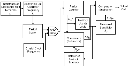
A simplified block diagram of a single channel, digital ratioed period-shift electronics unit is illustrated in Figure I-1. This electronics unit is similar to the digital period shift electronics unit except for the variable threshold count, which allows the sensitivity to be independent of the electronics unit oscillator frequency.
 |
Figure I-1. Digital ratioed period-shift electronics unit block diagram.
The ratioed period-shift electronics unit sensitivity SDpis given by
 |
(I-1) |
where the threshold count Npt is a constant and the count established by the period counter Npc is inversely proportional to the electronics unit oscillator frequency. The oscillator frequency is a function of loop inductance.
A variable threshold Npt is selected by multiplying the count established by the period counter by a preset sensitivity factor. Thus,
| (I-2) |
or
 |
(I-3) |
Previous | Table of Contents | Next
FHWA-HRT-06-139 |