U.S. Department of Transportation
Federal Highway Administration
1200 New Jersey Avenue, SE
Washington, DC 20590
202-366-4000
Federal Highway Administration Research and Technology
Coordinating, Developing, and Delivering Highway Transportation Innovations
 |
| This report is an archived publication and may contain dated technical, contact, and link information |
|
Publication Number: FHWA-HRT-06-139
Date: October 2006 |
| (1) | Inadequate hydro grounds at a service pole will allow energy from lightning discharge into the controller. Inspect Hydro grounds visually and arrange for the Supply Authority to repair faulty grounds. | |
| (2) | At controller sites where lightning problems have occurred, the Hydro ground should be reinforced to two 20 x 3000 mm copperclad rods at 3 m spacing at the service pole and at one hydro pole each way. Arrange purchase order for this work if necessary. | |
| (3) | Do not use Hydro ground as a Service ground. |
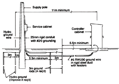
| (1) | To reduce voltages transferred from the Hydro ground (under lightning discharge) to the Service ground, the Service ground should be located as far from the Hydro ground as possible. See Figure O-1. | |
| (2) | The service ground should consist of a minimum of four 20 x 3000 mm copperclad ground rods on #2/0 bare copper wire grid as per Figure O-1. |

| (1) | Proper ground bus bar should be installed in the controller cabinet and all ground leads from equipment should connect to this one point. | |
| (2) | The controller cabinet ground bus should be connected to the service solid neutral by a #6AWG RWU90 insulated system ground wire. |
| (1) | Grounding system in areas of sand, gravel, or rock may require reinforcement due to poor soil conductivity. Refer to Electrical Design Manual—Volume 1. Request design aid from Electrical Engineering Section if necessary. |
| (1) | System ground wire for signals to be #16 AWG RWU90—40°C green. | |
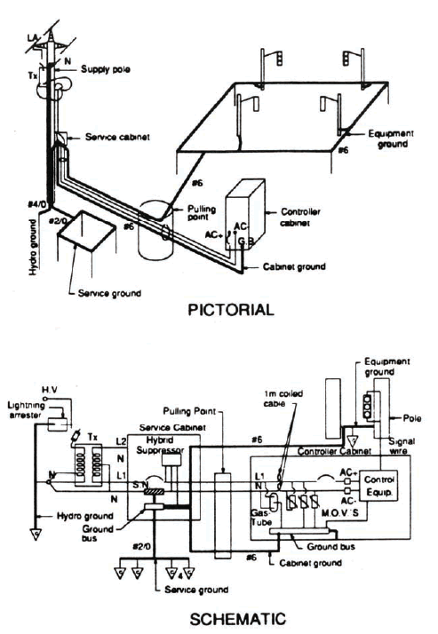
| (2) | Insta11 connections of the three systems (Service ground, cabinet ground, and equipment ground) as indicated in Figure O-2. | |
| (3) | Ensure that all metal enclosures are bonded to the proper section of the system ground. | |
| (4) | All connections to be thermit weld, impact or compression type (no split bolts, etc.). |
| (1) | Yearly inspection frequency for: | |
| (a) | Tight connections of accessible ground wires (controller cabinet and service); corrosion. | |
| (b) | Hydro and service grounds; visual for obvious damage from vehicles, etc. | |
| (c) | Testing of resistance to ground and soil conductivity (service ground) as per Subsection 8. |
| (1) | For controllers damaged by lightning: | |
| (a) | Inspection Hydro ground as per Subsection 1. | |
| (b) | Have Supply Authority check distribution arrestor and upgrade ground and arrestor if required. | |
| (c) | Inspect for proper installation of grounds as per Subsections 1 to 5. |

| (1) | Resistance to ground and soil conductivity should be measured at an ’average’ time of year. Measurements taken when soil is wet or frozen are not meaningful. | |
| (2) | Use the Megger ground resistance meter and the two small ground rods supplied with the unit. Follow instructions exactly for distances or results will be meaningless. For information regarding the instrument, contact the Electrical Operations Unit. | |
| (3) | Measurements to ground to be taken at the SN of the service and the controller cabinet ground bus. | |
| (4) | Resistance to ground and soil resistivity are related mathematically. See Electrical Design Manual—Volume 1, Section II. | |
| (5) | Resistance to ground should be 10 Ω or less but can vary up to 25 Ω in high resistivity soils. Readings over 25 O indicate that further inspection and repairs or replacement should be done or that additional rods and wire should be added (new installations). Add additional elements as per Table O-1. |
| (1) | Steel footings may be considered the equivalent of a ground rod for resistance to ground purposes. |
| (1) | One rod length spacing to be obtained between rods. |
| (2) | Connecting wire is more effective if buried to 1/2 the normal frost depth (assuming snow cover). |
| (3) | Do not install rods at more than 45° angle. Driving jaws for use with a hydraulic drive head are available. |
| (4) | Use 20 x 3000 mm copperclad rods only, with thermit weld or impact connectors. |
| Ground System Configuration | Description | Normal Use | Resistance to Ground(Ω) in Clay (ρ=100Ωm) | Resistance to Ground(Ω) in Sandy Clay (ρ=200Ωm) | Resistance to Ground(Ω) in clayey sand (ρ=500Ωm) | Resistance to Ground(Ω) in sand (ρ=1500Ωm) | Resistance to Ground(Ω) in sand, Gravel(ρ=5000Ωm) |
|---|---|---|---|---|---|---|---|
| 1. Single 20 mm x 3 m rod | Addition to system | 32 | 80 | 160 | 480 | 1610 | |
| 2. Single 220 mm dia. x 2300 mm steel footing | Poles (requires additional system) | 28 | 70 | 140 | 420 | 1400 | |
| 3. Single 85 mm dia. x 1830 mm steel footing | Poles, cabinets (requires additional system) | 40 | 100 | 200 | 600 | 2000 | |
| 4. 610 x 610 x 6 mm plate | Rock overburden 0.6 to 2.0 m | 46 | 115 | 230 | 690 | 2300 | |
| 5. Single #6 wire, bare, 3 m long | Addition to system | 41 | 103 | 205 | 615 | 2050 | |
| 6. Single #2/0 wire, bare, 3 m | long Addition to system | 38 | 95 | 190 | 570 | 1900 | |
| 7. Single #6 wire, 2 rods | Service | 19 | 38 | 95 | 290 | 950 | |
| 8. Single #2/0 wire, 2 plates | Service in overburden | 27 | 54 | 140 | 410 | 1400 | |
| 9. 220 mm dia. x 2300 mm steel footing, #6 wire, 1 rod | Poles | 19 | 38 | 95 | 285 | 950 | |
| 10. 85 mm dia. X 1830 mm steel footing, #6 wire, 1 rod | Poles | 16 | 34 | 80 | 240 | 800 | |
 | 11. 85 mm dia. x 1830 mm steel footing, #2/0 wire, 2 rods | Cabinets | 14 | 28 | 70 | 210 | 700 |
 | 12. 85 mm dia. x 1830 mm steel footing, #2/0 wire, 3 rods | Cabinets | 13 | 26 | 65 | 195 | 650 |
 | 13. 85 mm dia. x 1830 mm steel footing, #2/0 wire, 4 rods | Cabinets | 10 | 20 | 50 | 150 | 250 |
 | 14. #2/0 wire, 4 rods | Service Any for ρ < 125 Om | 11 | 22 | 55 | 165 | 550 |
 | 15. #2/0 wire, 4 rods, 2 ties | Any for ρ < 125 Om | 11 | 22 | 55 | 165 | 550 |
 | 16. #2/0 wire, 4 rods, 2 ties, 4 tails | Any for 125 < ρ < 150 Om | (9) | 18 | 45 | 135 | 450 |
 | 17. #2/0 wire, 4 rods, 2 ties, 8 tails | Any for 150 < ρ < 200 Om | (6) | 12 | 30 | 90 | 300 |
 | 18. #2/0 wire, 8 rods, 6 ties | Any for 200 < ρ < 350 Om | (5) | 10 | 25 | 75 | 250 |
| (1) | Grounding is a safety device and many members of the electrical industry are somewhat lax about proper grounding practices as the only times they are required are under abnormal conditions, such as short circuits and lightning surges. Poor workmanship or practices are not apparent until such an abnormal problem occurs. | |
| (2) | The Ministry’s grounding system practices should meet or exceed the requirements of the Code. (The Code is a minimum requirement). If doubt exists as to practice, the regulations contained in the Code should overrule other opinions. | |
| (3) | Workers should endeavor to follow the Ministry’s practices faithfully so as not to endanger themselves or the Ministry to the possibility of legal prosecution due to mishap through poor practice or application. |
| (1) | "Equipment, Manuals and Procedures Evaluation for the Design and Maintenance of Traffic Signal Systems,"Report No. 2, Grounding. Ministry of Transportation of Ontario, May 1988. |
Previous | Table of Contents | Next
FHWA-HRT-06-139 |