U.S. Department of Transportation
Federal Highway Administration
1200 New Jersey Avenue, SE
Washington, DC 20590
202-366-4000
Federal Highway Administration Research and Technology
Coordinating, Developing, and Delivering Highway Transportation Innovations
 |
| This report is an archived publication and may contain dated technical, contact, and link information |
|
Publication Number: FHWA-HRT-06-139
Date: October 2006 |
Agencies and vendors continue to search for better ways to manufacture and install inductive-loop detectors. The following sections describe two alternatives to conventional loops that have been developed, tested, and are currently operational. The conventional loop installation processes such as splicing, testing, etc., described earlier also apply to these alternative designs.
In the early 1980s, the Puerto Rico Highway Authority and the Department of Transportation and Public Works began to experiment with placing inductive-loop detectors in heavily reinforced precast concrete slabs for installation in bituminous pavements.(14) Earlier experimentation with loop detectors placed in cast-in-place concrete slabs 12 ft (3.7 m) in width and 6 ft (1.8 m) in length were unsuccessful due to the difficulties in maintaining traffic during the relatively long curing period. These slabs could not be precast because of their size and weight.
Puerto Rico selected smaller unitized slabs as an effective sensor design. They are used extensively for left-turn lane detection, off-ramp detection, arterial detection, and system detection.
The final design of the precast or cast-in-place loop slabs (both types are used) is 4 ft (1.2 m) square and 8 inch (20.3 cm) deep. A circular slot 40 inches (102 cm) in diameter, 3 inches (7.6 cm) deep, and 0.5–0.75 inches (13– 19 mm) wide is impressed in the concrete to house the conductors forming the loop.
Five turns of wire are standard in these installations, with three turns considered to be the minimum acceptable. Adequate vehicle detection has been obtained with up to 1,000 ft (300 m) of lead-in cable between the pull box and the electronics unit. After the wire is wound in the slot, a 5/8- to 7/8- inch (16- to 22-mm) nylon rope is forced into the slot on top of the loop wires and then the slot is filled with an asphalt sealant. A 1-inch (25-mm) flexible metallic conduct encloses the lead-in wires leading to the pull box.
As shown in the plan details in Figure 5-36, the slabs are provided with four lift point devices for handling during the original installation and for resetting in the case of overlays.(14) These slabs can be easily handled by two men and a small loader-backhoe combination.
Hot-poured asphaltic sealant and silicone sealant have been used successfully. An emulsified asphalt sealant is also being tested because it is less expensive and does not need to be heated. Epoxy sealant has not been used for this purpose because it may make reentry into the slot for repairs more difficult.
Although these slabs were originally intended for use on bituminous pavements, their performance and ease of maintenance have led to the use of slabs on new and existing PCC pavements. On existing PCC pavements, an oversized square is cut out of the pavement and the precast slab is installed with concrete backfill.
Puerto Rico uses nonreinforced concrete pavements. Therefore, on new PCC pavements, a grid of reinforcing bars is placed at the bottom of the new slab where the loop is to be placed prior to the pouring of the concrete. After the pour, a form for the slot is impressed into the fresh concrete.
| 1 inch = 2.5 cm |
Precast loop slabs have been used successfully in four basic configurations, as shown in Figure 5-37: actuation (LC-1), directional (LC-2), presence (LC-4), and high-speed detection (not shown on drawings). The loops have been connected in series and in parallel and have been used with standard and self-tuning electronics units.
Precast loop slabs have been installed at isolated intersections and in coordinated systems. In coordinated systems, they have been used for both local detection and as strategic system sensors to feed information to the master controller for traffic-responsive operation.
By 1988, there were more than 1,800 slab-loop detectors installed in Puerto Rico. Over a 5-year period there had been no traffic- or pavement-induced failures. On three occasions, excavations in the sidewalk or adjacent pavement areas had damaged the lead-in wires. In addition, 13 incidences of failure in the wire insulation resulted from a manufacturing error.
Although Puerto Rico experiences heavy rainfall, the annual temperature falls between a low normally about 60 °F (16 °C) and a high normally below 97 °F (36 °C). Consequently, there is no freeze-thaw problem. Freeze-thaw could possibly affect the use of these slabs in colder climates.
Those failures provided opportunities to demonstrate the ease with which loops can be repaired. With a screwdriver or similar tool, the nylon rope is pried from the slot and, by pulling on the rope, the rope and sealant are removed. The conductor wires are then removed from the slot. New conductors, rope, and sealant are then installed and an epoxy-encapsulated splice is made at the nearest pull box. This completes the repair with little disruption to traffic.
Figure 5-37. Precast loop slab configurations.
Loop slabs have been very successful in Puerto Rico. Typical installations on an off-ramp and in a left-turn lane are shown in Figure 5-38. In the mid- 1980s, the cost in Puerto Rico was approximately $350 per loop, including the slab, installation, conduit, wiring to the nearest pull box, and the splice at that pull box.
Older signal projects with sawed slots in the pavement are being retrofitted with precast slabs to prevent the deterioration and interruption of service due to loop failures. Although a formal benefit/cost comparison has not been conducted between the precast and the sawed loop detectors, the zero failure rate of the precast system during a 5-year operating period is considered sufficient justification for Puerto Rico to adopt the precast loop as standard practice.
Although square or rectangular loops are the most commonly used shapes, many loop designers have theorized that circular loops would provide optimum detection characteristics. In theory, the round loop will produce a uniform magnetic field without dead spots.
Proponents of the round loop argue that the circular design maximizes loop sensitivity for detection of motorcycles as well as high-bed trucks while eliminating splashover from adjacent lanes. Other advantages cited include the elimination of sharp corners and the reduction in wire stress. Modern cutting techniques appear to have eliminated the difficulty associated with cutting the circular shape in the pavement.
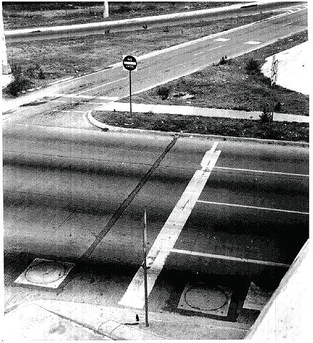
Figure 5-38. Slab-loop installations.
One installer has addressed the cutting issue by developing a patented vehicle designed to saw a circular slot 6 ft (1.8 m) in diameter, 0.5 inch (1.25 cm) wide, and 3 inches (7.6 cm) deep for circular loop installation in either asphalt or concrete road surfaces.(15) The self-contained vehicle, shown in Figure 5-39, is equipped with a 6-ft (1.8-m) diameter bit to cut the circle, a 500-gallon (1.9-kiloliters) water supply, central vacuum system, a 6.5-kVA generator, arrow boards front and rear, portable hot sealant unit, and a 35- hp flat saw for cutting the slot from the loop to the pull box. The loop wire used in this installation is encased in continuous PVC tubing and prewound for the specified number of turns, stacked, and taped at the factory.
A typical roadway installation process is illustrated in Figures 5-39 through 5-41. The truck arrives at the site and the two-man crew sets out cones to divert traffic. The lift gate is used to off-load the hot rubberized sealant machine and the flat saw. The sealant material is placed in the machine to melt to pumping consistency. A center mark for the drilling bit is marked on the roadway. The truck is positioned to center the bit over the mark and the platform holding the bit is lowered. The drive button on the control panel is depressed to activate the bit. The depth gauge on the bit allows the operator to monitor the accuracy of the depth of the cut. When the proper depth is reached, the drive button is released and the bit comes to a stop. The platform is raised and the truck can be repositioned for the next cut. The average cutting time is 5 minutes.
The flat saw is used to cut the slot from the loop to the pull box. A 3-inch (7.6-cm) core is drilled at the point where the lead-in slot joins the circle. After all cuts have been made, the slots are washed out to remove debris and vacuumed dry.
The prewound loop and its lead-in wires are then installed. All loops are wound in a clockwise pattern and are connected in series. The top wire is wound around the 3-inch (7.6-cm) core to reduce bending stress. The installation is now ready to be sealed. The sealant is pumped into the slot after it reaches its melting point. The installation is complete when the sealant is applied, and the lane may be opened to traffic immediately as the sealant hardens as soon as it is exposed to air.
The circular loop installer reports that since the truck and cutting tool are a totally self-contained unit, the loop cutting operation can be confined to a single lane at a time. The body of the truck faces oncoming traffic, which provides an added measure of protection for the operator and others working in the area. Thus the loop cutting can be accomplished safely, in minimal time, and with minimal disruption to traffic flow in the area.
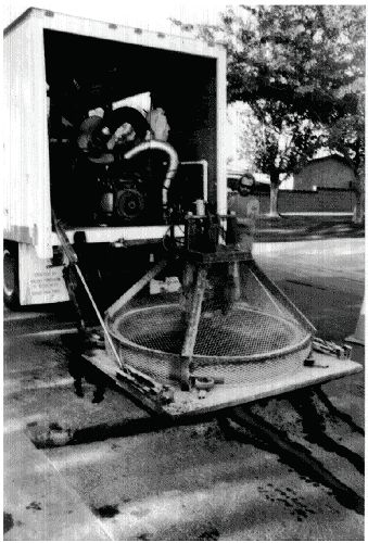
Figure 5-39. Roadway installation of round loops—cutting loop circle.
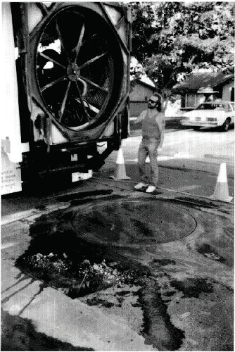
Figure 5-40. Roadway installation of round loops—retraction of saw.
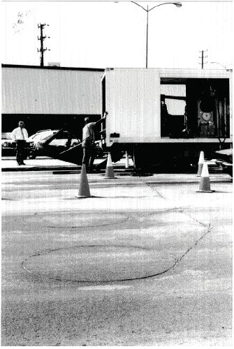
Figure 5-41. Roadway installation of round loops—completed installation.
Other cutting equipment is used to cut round loops in more confined areas such as sidewalks. The series of photographs showing the installation procedure using this equipment is found in Figures 5-42 through 5-52 and was provided by the Traffic Signal Laboratory at Purdue University.
There is debate regarding placing backer rod material over the entire wire or simply using short pieces of material every foot or so. The first method supports easier installation from the contractor’s perspective; the second provides better encapsulation by the sealant and less wire movement.
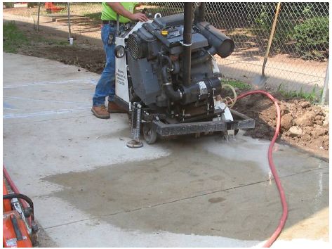
Figure 5-42. Round loop saw at beginning of installation process.
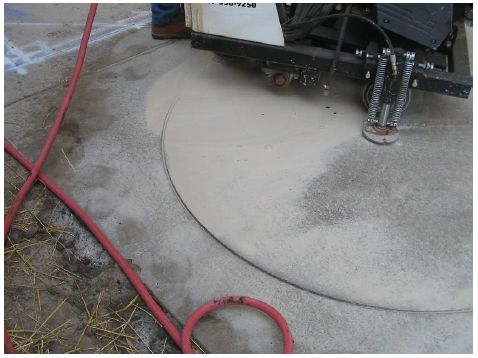
Figure 5-43. Round sawcut in process.
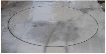
Figure 5-44. Completed round sawcut.
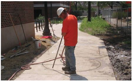
Figure 5-45. Blowing out debris from sawcut.
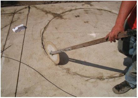
Figure 5-46. Firmly seating loop wire in sawcut with rolling-blade tool.
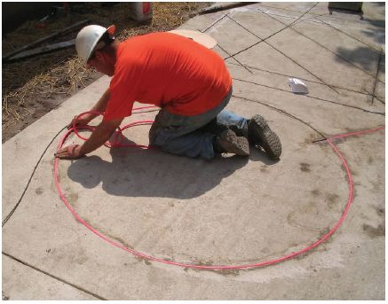
Figure 5-47. Inserting backer rod material over loop wire.
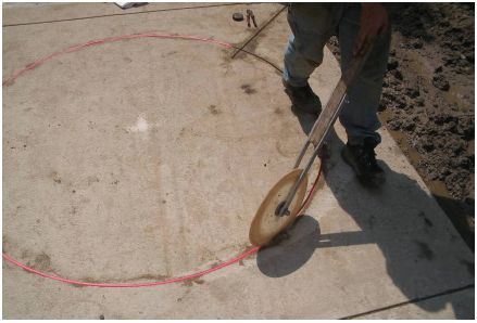
Figure 5-48. Firmly seating backer rod material over loop wire.
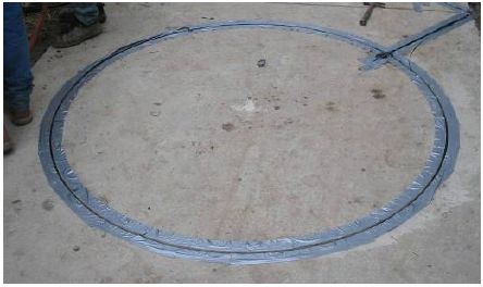
Figure 5-49. Tape placed around both sides of sawcut to prevent sealant from adhering to concrete.
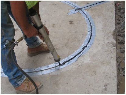
Figure 5-50. Placing sealant in sawcut.
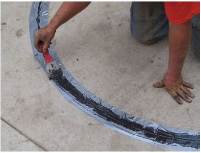
Figure 5-51. Removing excess sealant.
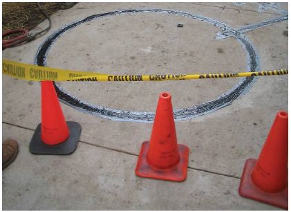
Figure 5-52. Isolation of affected area to allow sealant to dry.
Previous | Table of Contents | Next
FHWA-HRT-06-139 |

