U.S. Department of Transportation
Federal Highway Administration
1200 New Jersey Avenue, SE
Washington, DC 20590
202-366-4000
Federal Highway Administration Research and Technology
Coordinating, Developing, and Delivering Highway Transportation Innovations
 |
| This report is an archived publication and may contain dated technical, contact, and link information |
|
Publication Number: FHWA-HRT-04-091
Date: August 2004 |
||||||||||||||||||||||||||||||||||||||||||||||||||||||||||||||||||||||||||||||||||||||||||||||||||||||||||||||||||||||||||||||||||||||||||||||||||||||||||||||||||||||||||||||||||||||||||||||||||||||||||||||||||||||||||||||||||||||||||||||||||||||||||||||||||||||||||||||||||||||||||||||||||||||||||||||||||||||||||||||||||||||||||||||||||||||||||||||||||||||||||||||||||||||||||||||||||||||||||||||||||||||||||||||||||||||||||||||||||||||||||||||||||
Signalized Intersections: Informational GuidePDF Version (10.84 MB)
PDF files can be viewed with the Acrobat® Reader® CHAPTER 10 — ALTERNATIVE INTERSECTION TREATMENTSTABLE OF CONTENTS 10.0 ALTERNATIVE INTERSECTION TREATMENTS 10.1 Intersection Reconfiguration and Realignment treatments 10.1.1 Remove intersection Skew Angle 10.1.2 Remove Deflection in Travel Path for Through Vehicles 10.1.3 Convert four-Leg Intersection to Two T-Intersections 10.1.4 Convert two T-Intersections to Four-Leg Intersection 10.2 Indirect Left-Turn Treatments 10.2.2 Median U-Turn Crossover 10.2.3 Continuous Flow Intersection 10.2.4 Quadrant Roadway intersection 10.2.5 Super-Street Median Crossover 10.3 Grade-Separation Treatments
LIST OF FIGURES
LIST OF TABLES
10. Alternative Intersection TreatmentsA recent study has shown that conventional methods of adding capacity to an intersection adding left-turn, through, and right-turn lanes-have diminishing returns.(138) For example, if the addition of a second through lane adds 15 years to the life of the intersection before it reaches capacity, the addition of a third through lane adds only 10 years, and a fourth through lane adds only 6 years. Large intersections increase loss time due to longer clearance intervals, protected left-turn phasing, longer pedestrian clearance times, greater imbalances in lane utilization, and potential queue blockages caused by the resulting longer cycle lengths. Each of these issues suggests the need to look for alternative methods to conventional lane additions to solving congestion-related problems. This chapter describes reconstruction treatments for signalized intersections in three categories: intersection reconfiguration, at-grade indirect movements, and grade separation. Many of these treatments are commonplace; others have seen limited or regional use. The common element in each treatment is the reduction in conflict points at the intersection, which provides safety and operational benefits by reducing the number of phases and conflicting volume at a single location. These reconstruction treatments are often necessary when relatively low-cost treatments (such as improving signal timing and signing or adding an auxiliary lane) do not suffice. Given that limited data are available regarding the safety of these treatments, a conflict point diagram is provided so that the treatments presented here can be compared to a conventional four-leg signalized intersection (figure 72). At a conventional four-leg signalized intersection, conflict points can be categorized as follows:
Figure 72. Illustration of conflict points for a four-leg signalized intersection. 10.1 Intersection Reconfiguration and Realignment treatmentsThis section discusses several conventional at-grade treatments that can solve specific intersection problems. 10.1.1 Remove intersection Skew AngleDescriptionThe AASHTO policy suggests maintaining an intersection angle of 75 to 90 degrees for new construction.(3) Angles as low as 60 degrees are acceptable if cost and other constraints dictate a need for this degree of skew. If reconstructed intersections have a skew angle below 60 degrees, examination of collision rates and patterns may be required. Signalized intersections may have sight-distance-related safety problems that cannot be addressed inexpensively (such as clearing sight triangles, adjusting signal phasing, or prohibiting turning movements). These may require horizontal or vertical realignment of approaches. Realigning both of the minor-road approaches so that they intersect the major road at a different location or a different angle can help address horizontal sight distance issues. Such strategies should generally be considered only at intersections with a persistent crash pattern that cannot be changed by less expensive methods, such as clearing sight triangles at intersections and in medians. Examples of different types of realignment are shown in figure 73.
Figure 73. Diagrams of different types of intersection realignment.(3, Exhibit 9-18) ApplicabilityRealignment of the approaches on an intersection may be applicable where severe collision problems occur. Safety PerformanceAt skewed intersections, crossing distances are lengthened and the conflict area within the intersection is greater. This increases the potential for collisions. Roads that intersect with each other at angles less than 90 degrees can present sight-distance and operational problems for drivers. A high incidence of right-angle accidents, particularly involving vehicles approaching from the acute angle, may be the result of a problem associated with skew. Because vehicles have a longer distance to travel through the intersection (increasing their exposure to conflicts), drivers may find it difficult to look to the left at an approach on an acute angle, and vehicles turning right at an acute angle may encroach on vehicles approaching from the opposite direction. When right turns on red are permitted, drivers may have more difficulty judging gaps when turning. Also, crossing distances for pedestrians are increased. Skewed intersections, in addition to potentially having intersection sight-distance problems, could also present a different sight obstruction for drivers. It is possible that the vehicle body itself could block a driver's view of the cross road, depending on the angle of the skew, the position of the vehicle on the roadway, and the position of the driver in the vehicle.(43) Skewed intersections pose particular problems for older drivers, many of whom experience a decline in head and neck mobility. A restricted range of motion reduces older drivers ability to effectively scan to the rear and sides of the vehicle to observe blind spots. They may also have trouble identifying gaps in traffic when making a left turn, or safely merging with traffic when making a right turn.(12) No specific references to safety benefits of removing intersection skew were found. If utility poles and/or illumination running alongside the road remain in the same location after alignment, they may create a visual illusion that the road is still in its old alignment. A low-cost solution is to provide delineation on the curves at the beginning of the realignment, but some collisions may still occur. Operational PerformanceAny improvement to intersection skew will improve operations involving turning vehicles. In addition, improvement to intersection skew often reduces vehicle and pedestrian clearance time, which may result in an overall reduction in delay to all users. Because such projects are significant undertakings, the number of through and turning lanes and signal phasing should be reevaluated; this may result in a significant improvement in intersection operations. Multimodal ImpactsAs highly skewed intersections mean longer crossing distances for pedestrians, any improvement in skew angle will reduce pedestrian exposure to traffic and likely improve pedestrian safety. Longer commercial vehicles will have considerable difficulty turning at an intersection where adjacent legs meet at an angle at less than 60 degrees. Considerable off-tracking will occur. Any improvement to skew angle will particularly improve the safety and operation when these vehicles attempt such turns. Physical ImpactsTraffic signals, controllers, signage, and illumination may all have to be relocated if this treatment is undertaken. Socioeconomic ImpactsRemoving intersection skew may involve acquisition of adjacent land, removal of structures, and relocation of road furniture. If this is the case, this improvement may be costly. SummaryTable 63 summarizes the issues associated with removing intersection skew. Table 63. Summary of issues for removing intersection skew.
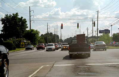
10.1.2 Remove Deflection in Travel Path for Through VehiclesIntersections with substantial deflections between approach alignments can produce operational and safety problems for through vehicles as they navigate through an intersection. Forced path changes for through vehicles violate driver expectations and may pose problems for unfamiliar drivers. Violation of driver expectancy can result in reduced speeds through the intersection. Crashes influenced by a deflection in travel path are likely to include rear-end, sideswipe, head-on, and left-turning/through crashes. Acceptable deflection angles through intersections vary by individual agency, but are typically related to the design and/or posted speed on an intersection approach. Typical maximum deflection angles are 3 to 5 degrees. An example of deflection in through-vehicle travel paths is shown in figure 74. ApplicabilityRemoving deflection in the through vehicle travel path is applicable as a treatment where:
Safety PerformanceRedesign of an intersection approach (or approaches) to eliminate deflection in the through vehicle travel path should eliminate crashes related to the situation. Proper design of an intersection should provide traffic lanes that are clearly visible to drivers at all times, clearly understandable for any desired direction of travel, free from the potential for conflicts to appear suddenly, and consistent in design with the portions of the highway approaching the intersection. The sight distance should be equal to or greater than minimum values for specific interchange conditions.
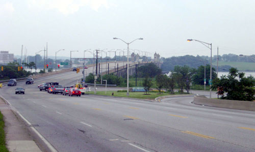
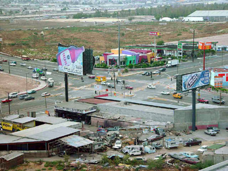
Photograph Credit: Lee Rodegerdts, 2003 Figure 74. Example of deflection in travel paths for through vehicles. OperationsEliminating deflection for through vehicles will improve traffic flow, although the amount of improvement may be difficult to quantify. No existing analytical or simulation models are sensitive to deflection of through vehicles. Multimodal ImpactsRedesign of an intersection approach or approaches will particularly benefit heavy vehicles and buses by reducing the amount of off-tracking as they proceed through the intersection. Physical ImpactsAdditional right-of-way may be required to realign through lanes. Socioeconomic ImpactsEliminating deflection should be done for a low to moderate cost. Impacts may be largely confined to one side of the intersection. SummaryTable 64 summarizes the issues associated with the removal of vehicle path deflection. Table 64. Summary of issues for removing deflection of vehicle path.
10.1.3 Convert four-Leg Intersection to Two T-IntersectionsFor some signalized four-leg intersections with very low through volumes on the cross street, the best method of improving safety may be to convert the intersection to two T-intersections. This conversion to two T-intersections can be accomplished by realigning the two cross-street approaches an appreciable distance along the major road, thus creating separate intersections that operate relatively independently of one another. ApplicabilityThis improvement may be applicable to signalized four-leg intersections with very low through volumes on the cross street, yet having a relatively high number of unusually severe collisions. Safety PerformanceIn a study conducted by Hanna et al., offset intersections had collision rates that were approximately 43 percent of the accident rate at comparable four-leg intersections.(139) This study did not differentiate between signalized and nonsignalized intersections. Table 65 shows the number of merging, diverging and crossing (left-turn and angle) conflicts for two closely spaced t-intersections as compared to a four-leg signalized intersection. Compared to a four-leg signalized intersection, two closely spaced t-intersections have less merge/diverge and left-turn crossing conflict points and no angle crossing conflict points. Figure 75 shows the conflict point diagram for two closely spaced t-intersections. Table 65. Number of conflict points at a four-leg signalized intersection compared to two closely spaced t-intersections.
Figure 75. Conflict point diagram for two closely spaced t-intersections Table 66 summarizes the expert opinion of the authors with regard to the safety benefits of a conversion of a four-leg signalized intersection to two T-intersections. Table 66. Safety benefits of converting a four-leg signalized intersection to two
Operational PerformanceIf through volumes on the minor street are high, the intersection may be safer if left as a conventional four-leg intersection. Converting it to two T-intersections would only create excessive turning movements at each of the t-intersections. Another potential difficulty with this strategy is the spacing between the two T-intersections. If they are not spaced far enough apart, two problems can occur. First, there may not be enough storage length for the left-turning vehicles between the two intersections if left-turn movements overlap (negative offset). Second, the operation of the two intersections may interfere with one another. In general, the offset t-intersection arrangement where major street left turns do not overlap (positive offset) is better because it eliminates the problem of queue overlap for the major street left turns. Another difficulty may occur in providing safe access to the properties adjacent to the former four-leg intersection. Driveway access should be considered during the design process. Multimodal ImpactsNo significant multimodal impacts are expected. The smaller T-intersections may have shorter pedestrian clearance times and shorter cycle lengths, resulting in shorter overall delay for pedestrians and cyclists. Physical ImpactsThe intersections should be separated enough to ensure the provision of adequate turn-lane channelization on the major road. Relocation of traffic signals, signage, and other street furniture would be required. This treatment would involve purchasing an additional set of traffic signals. Socioeconomic ImpactsSignificant costs would be associated with this improvement. Enforcement, Education, and maintenanceDue to the change in traffic patterns necessitated by this treatment, public acceptance and understanding of the issues and reasons for converting the intersection will be an important consideration. SummaryTable 67 summarizes the issues associated with the conversion of a four-leg intersection to two T-intersections. Table 67. Summary of issues for converting a four-leg intersection to two
10.1.4 Convert two T-Intersections to Four-Leg IntersectionFor some signalized offset t-intersections with very high through volumes on the cross street, the best method for improving safety may be to convert the intersection to a single four-leg intersection. This can be accomplished by realigning the two cross-street approaches to meet at a single point along the major road. ApplicabilityThis improvement may be considered for signalized offset t-intersections with very high through volumes on the cross street and a high frequency of collisions associated with turning movements involving traffic on the cross street. Safety PerformanceIn the previous section, it was suggested that converting a four-leg intersection to two T-intersections would lead to an improvement in safety using conflict points as a surrogate. However, in some circumstances, two T-intersections may be experiencing safety problems due to the conditions described above that could be addressed through a conversion to a four-leg intersection. It is expected that this strategy would reduce collisions involving left-turning traffic from the major road onto the cross street at each of the two T-intersections. It can reduce or eliminate safety problems associated with insufficient spacing between existing offset t-intersections. Operational PerformanceThe success of this strategy depends on the through volume of the cross street. If through volumes are low, the intersection may be safer if left as two offset t-intersections. Two offset t-intersections with low through volumes on the cross street are generally safer than a four-leg intersection. Multimodal ImpactsNo significant multimodal impacts are expected. The larger single intersection may have longer pedestrian clearance times and longer cycle lengths, resulting in longer overall delay for pedestrians and cyclists. Physical ImpactsRelocation of traffic signals, signage, and other street furniture would be required. This treatment would involve the removal of one set of traffic signals. Socioeconomic ImpactsSignificant costs would be associated with this improvement. Enforcement, Education, and maintenanceDue to the change in traffic patterns involved in carrying out this treatment, public acceptance and understanding of the issues and reasons for converting the intersection will be an important consideration. SummaryTable 68 summarizes the issues associated with the conversion of two T-intersections to a four-leg intersection. Table 68. Summary of issues for converting two T-intersections to one four-leg intersection.
10.1.5 Close intersection LegFor some signalized intersections with severe crash histories, the best way to improve safety may be to close a leg or convert one leg to a one-way movement away from the intersection. Closing a leg should generally be considered only when less restrictive measures have been tried and have failed. Closing a leg can be accomplished by closing and abandoning a minor approach using channelizing devices or by reconstructing the minor approach so it ends before reaching the intersection with the major street. Though it is a significant modification to an intersection, it can be a low-cost treatment. This treatment may be most applicable to intersections with more than four legs. ApplicabilityThis treatment may be considered in situations where other treatments with fewer impacts have failed. Possible applications are in situations where a high and unusually severe number of collisions are occurring that involve movements to and from the leg in question. Safety PerformanceClosing a leg should eliminate crashes related to that leg. Consideration must be given to the adjacent intersections and to alternative routes onto which traffic would be diverted, and the potential impact to safety on those routes. Estimates of safety benefits are shown in table 69. Table 69. Safety benefits associated with street closures: Selected findings.
Operational PerformanceClosing a leg will mean simplifying the signal phasing and may mean a shorter cycle. However, closing a leg will considerably alter traffic patterns in the area if volumes on the leg to be closed are significant. The capacity of surrounding roads and intersections to accommodate the diverted traffic will need to be considered. Transit operations may be significantly impacted if routes use the leg being closed. Physical ImpactsIn closing a leg, a barrier will need to be constructed. This barrier should be aesthetically pleasing, even if temporary. Landscaping should be considered after it is determined that this closure will be permanent. Multimodal ImpactsIt may be possible to maintain pedestrian and bicycle connections to the closed leg, thus maintaining existing circulation patterns. If such connections can be maintained, the closure may help to promote a more pedestrian-friendly environment. Socioeconomic ImpactsDue to the significant change in traffic patterns involved, public acceptance and understanding of the issues and reasons for converting the intersection are critical (particularly for residents or businesses on the closed leg). Enforcement, Education, and maintenanceSuch a treatment would need agreement from all emergency services, as emergency response could be significantly affected. SummaryTable 70 summarizes the issues associated with closing an intersection approach leg. Table 70. Summary of issues for closing an intersection approach leg.
10.2 Indirect Left-Turn TreatmentsIndirect left turns can improve the safety and operations of high-volume intersections. These designs remove the left-turning vehicles from the traffic stream without causing them to slow down or stop in a through-traffic lane, thereby reducing the potential for delay and rear-end crashes. Right-angle crashes are also likely to decrease after indirect left-turn treatments are implemented. Such treatments are effective on divided highways with medians too narrow to accommodate left-turn lanes with sufficient storage capacity. An overview of these types of intersection forms can be found in several sources.(141,142,143) In some cases, it is possible to implement indirect left turns using appropriate signing. Implementation costs and time could be quite high, however, if right-of-way needs to be acquired to construct indirect left turns. Care should be taken to ensure that safety problems are not transferred to nearby intersections if drivers choose alternative routes. Clear signing is a necessity for indirect left-turn designs, especially if there are not similar treatments at other intersections in an area. 10.2.1 JughandleAs defined in the New Jersey Department of Transportation (NJDOT) design manual, a jughandle is "an at-grade ramp provided at or between intersections to permit the motorists to make indirect left turns and/or U-turns."(144) The NJDOT has used jughandles for years to minimize left-turn conflicts at intersections. Other States that have implemented jughandles to a lesser degree include Connecticut, Delaware, Oregon, and Pennsylvania. Jughandles are one-way roadways in two quadrants of the intersection that allow for removal of left-turning traffic from the through stream without providing left-turn lanes. All turns-right, left, and U-turns are made from the right side of the roadway. Drivers wishing to turn left exit the major roadway at a ramp on the right and turn left onto the minor road at a terminus separated from the main intersection. Less right-of-way is needed along the roadway because left-turn lanes are unnecessary. However, more right-of-way is needed at the intersection to accommodate the jughandles. Figure 76 illustrates a jughandle intersection with the ramps located in advance of the intersection. The various possible movements are illustrated in figure 77. As can be seen, vehicles on the major street use the ramp to make turning movements at the intersection. Examples are shown in figures 78 and 79.
Figure 76. Diagram of a jughandle intersection.(adapted from 145)
Figure 77. Vehicular movements at a jughandle intersection.
Figure 78. Example of a jughandle intersection.
Figure 79. Another example of a jughandle intersection. ApplicabilityJughandles may be appropriate at intersections with high major street through movements, low-to-medium left turns from the major street, low-to-medium left turns from the minor street, and any amount of minor street through volumes.(141) Intersections too small to allow large vehicles to turn left, as well as intersections with medians too narrow to provide a left-turn lane, may also be appropriate locations for jughandles. Jughandles address safety deficiencies involving left-turn collisions and operational deficiencies due to the lack of available green time for major-street through movements. Design FeaturesThe NJDOT design manual provides design guidelines for jughandles.(144) Jughandles commonly are constructed in advance of the intersection (see figure 80). If left-turn movements onto the cross street are problematic, a loop ramp may be constructed beyond the intersection to allow these vehicles to make a right turn onto the cross street, as shown in figure 81. The disadvantage is that additional right-of-way is needed to accommodate the loop ramp and the travel distance is greater. Note that although the cited guidelines do not show pedestrian or bicycle facilities, these should be included in as appropriate. Key features from the design manual are summarized below:
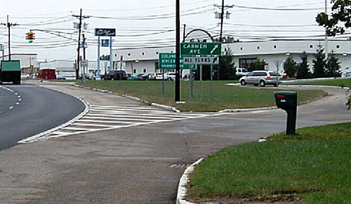
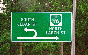
Signing at jughandle intersections is critical, as drivers need to be given an indication that they must exit to the right to make a left turn. Figure 82 gives an example of signing used in New Jersey. Because jughandles are relatively common in New Jersey, the signing employed is perhaps more minimal than might be considered in other areas where jughandles are more novel.
Figure 81. Design layout of far-side jughandle.(adapted from 144)
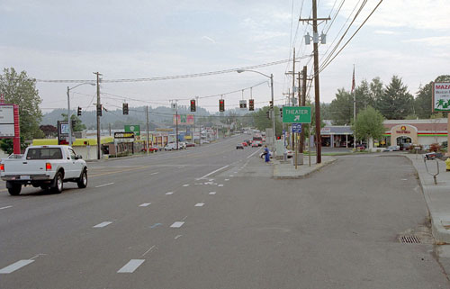
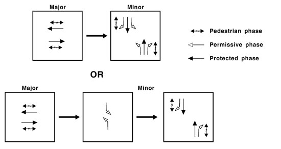
Photograph Credit and Copyright: Arthur Eisdorfer, 2002. Figure 82. Example of jughandle and associated signing. Operational FeaturesThe jughandle should operate with stop control at the minor street approach. Right turns onto the cross street may operate with yield control. Signing is needed in advance of the jughandle ramp to indicate that motorists destined to the left need to exit the roadway from the right-hand lane. With the removal of left-turn lanes at the signalized intersection location, the signal can be operated with either two or three phases, as shown in figure 83. The third phase would be needed to accommodate minor street left-turn movements. The reduction in phases allows for either shorter cycle times or allocation of green times to the major street through movements. Shorter cycle lengths should be considered to minimize vehicle queues on the cross street.
Figure 83. Signal phasing of a jughandle intersection. Safety PerformanceJughandles remove left-turning vehicles from the through lanes and thus are likely to reduce crashes as long as sufficient signing is provided to help eliminate driver confusion. The NJDOT has constructed many jughandle intersections; these are considered to be safe. No significant increase in crashes has been experienced since the implementation of the jughandles, though a decrease in crashes is not reported, either.(146) Driver confusion may result when jughandles are first constructed in an area. Also, areas with significant numbers of unfamiliar drivers may experience problems related to driver confusion, even after the jughandles are no longer new. Signing should be used to inform drivers how to make turns. a public information campaign leading up to the opening of the new ramp(s) may be appropriate. Visual cues can reduce the amount of driver confusion. A raised concrete median barrier, installed to separate opposing directions of travel, may lead drivers to expect that turns from the left are not possible, and may explain why the collision experience at New Jersey jughandles has been good.(146) Pedestrians on the cross street will have to cross the ramp terminal, thus increasing their exposure to potential conflict. The main intersection, however, will maintain a minimum width, and crossing distance will not increase (as it would with construction of a left-turn lane). Table 71 shows the number of conflict points at a four-leg signalized intersection as compared to a four-leg signalized intersection with two jughandles. A four-leg signalized intersection with two jughandles would have fewer crossing (left-turn) conflict points. Figure 84 shows the conflict point diagram for a four-leg signalized intersection with two jughandles. Table 71. Number of conflict points at a four-leg signalized intersection compared to a four-leg signalized intersection with a jughandle.
Figure 84. Conflict point diagram for a four-leg signalized intersection with two jughandles. Table 72 summarizes the expert opinion of the authors with regard to the safety benefits of a conversion of a four-leg signalized intersection to four-leg signalized intersection with two jughandles. Table 72. Safety benefits of converting a four-leg signalized intersection to a four-leg signalized intersection with two jughandles: Expert opinion.
Operational PerformanceThe operations of a jughandle are best represented through the use of microsimulation models. A microsimulation model reflects the queue interaction between the signalized intersection and the minor street/ramp terminal intersection. An isolated intersection analysis can be used to determine the appropriate phases and signal timing parameters for the signalized intersection. General findings regarding the operational performance of jughandles are summarized below:
Multimodal ImpactsWith jughandle ramps in place, left-turn lanes are not needed along the mainline; this may reduce the roadway cross section and reduce the amount of pedestrian crossing distance. The elimination of the major street left-turn phase may enable shorter cycle lengths that reduce the amount of delay for pedestrians. Bicycle lanes should remain at the outside lane and include dotted lines where right-turning vehicles are required to cross to enter the jughandle. Conflicts are reduced at the intersection given that right turns have already been separated from the through travel lane. Because of the close proximity of the jughandle ramps to the main intersection, transit stops should be located outside the influence area of the intersection, including the jughandle ramps. This will minimize potential queuing conflicts. Physical ImpactsThe amount of land required for construction of a jughandle ramp depends on the storage and super elevation requirements of the ramp. The NJDOT design manual recommends a minimum of 30 m (100 ft) between the ramp terminal intersection at the cross street and the stop bar for the signalized intersection.(144) Hummer and Reid suggest that each jughandle typically requires a triangle 120 m (400 ft) by 90 m (300 ft).(141) The infield area created by the ramp may be used as a drainage basin; however, the water surface should be located outside the clear zone.(144) Additional landscaping maintenance may be required for the infield area. An option that may have fewer impacts is to implement a virtual jughandle by using an existing grid network to divert traffic around the block rather than permitting left turns at the major street intersection. SummaryTable 73 summarizes the issues associated with jughandles. Table 73. Summary of issues for jughandles.
10.2.2 Median U-Turn CrossoverMedian U-turn crossovers eliminate left turns at intersections and move them to median crossovers beyond the intersection. For median U-turn crossovers located on the major road, drivers turn left off the major road by passing through the intersection, making a U-turn at the crossover, and turning right at the cross road. Drivers wishing to turn left onto the major road from the cross street turn right onto the major road and make a U-turn at the crossover. Figure 85 illustrates a median U-turn configuration, and figure 86 illustrates some of the vehicle movements at such an intersection.
Figure 85. Diagram of a median U-turn crossover from the main line.(adapted from 145)
Figure 86. Vehicular movements at a median U-turn intersection. The median crossover may also be located on the minor road. In this case, drivers wishing to turn left from the major road turn right on the minor road, and left through the median crossover. Minor road vehicles turn left onto the major road by proceeding through the intersection, making a U-turn, and turning right at the major road. Median U-turn crossovers also may be provided on both the major and minor roads at an intersection. Median U-turn crossovers are very common in Michigan, and drivers are very familiar with them. They have been in use for more than 30 years, and the signing has evolved to become more user friendly.(141) Figure 87 shows an example of median U-turn signing used in Michigan.
Photograph Credit: Lee Rodegerdts, 2002 Figure 87. Example of median U-turn signing in Michigan. ApplicabilityDue to the design, median U-turn crossovers require a wide median to enable the U-turn movement. Median U-turns may be appropriate at intersections with high major-street through movements, low-to-medium left turns from the major street, low-to-medium left turns from the minor street, and any amount of minor street through volumes.(141) Locations with high left-turning volumes may not be good candidates because the out-of-direction travel incurred and the potential for queue spill back at the median U-turn location could outweigh the benefits associated with removing left-turns from the main intersection.(141) Median U-turns can be applied on a single approach. Design FeaturesKey design features of median U-turns identified in the literature are summarized below:
 Figure 88. Diagram of general placement of a median U-turn crossover.(adapted from 147)
Figure 89. Diagram of a median U-turn crossover from the main line with a narrow median.(adapted from 148) Operational FeaturesKey items regarding the operational features of median U-turns are summarized below:
Safety PerformanceAccording to NCHRP 420, the collision rate along road sections having directional median openings (facilitating U-turn and left turns) versus road sections having full median openings (facilitating all movements) was 49 to 52 percent less for signalized corridors having more than one traffic signal per mile.(85) Table 74 shows the number of conflict points at a four-leg signalized intersection as compared to a four-leg signalized intersection with a median U-turn crossover. A median U-turn crossover configuration eliminates all crossing (left turn) conflict points. It also reduces the number of merge/diverge conflict points as compared to a four-leg signalized intersection. Figure 90 shows the conflict point diagram for a four-leg signalized intersection with a median U-turn crossover configuration. Table 74. Number of conflict points at a four-leg signalized intersection compared to a four-leg signalized intersection with a median U-turn crossover configuration.
Figure 90. Conflict diagram for a four-leg signalized intersection with median U-turns. Table 75 summarizes the expert opinion of the authors with regard to the safety benefits of a conversion of a four-leg signalized intersection to a median U-turn crossover configuration. Table 75. Safety benefits of converting a four-leg signalized intersection to median U-turn crossover configuration: Expert opinion.
Operational PerformanceKey elements regarding the operational performance of median U-turns are summarized below:
Multimodal ImpactsRoadways with median U-turns generally have a greater cross section width resulting in an increased crossing distance for pedestrians. The number of movements that conflict with pedestrians at intersections with upstream/downstream median U-turns is reduced. Turning paths of the median U-turn should be evaluated to ensure that vehicle paths do not encroach on bike lanes. Socioeconomic ImpactsAccess should be restricted on facilities within the influence of median U-turn locations. Local property owners may oppose such restrictions, particularly if the access already exists. Education, Enforcement, and maintenanceEducation and enforcement are needed to ensure that vehicles are not making illegal left turns at the main intersection. SummaryTable 76 summarizes the issues associated with median U-turn crossovers. Table 76. Summary of issues for median U-turn crossovers.
10.2.3 Continuous Flow IntersectionContinuous flow intersections (CFI), both full and partial, have recently been constructed in a small number of locations in the United States. Although too new for a full evaluation of the effect on operations and safety, continuous flow intersections are gaining in popularity. CFI are also sometimes referred to as crossover-displaced left-turn (XDL) intersections. DescriptionA CFI removes the conflict between left-turning vehicles and oncoming traffic by introducing a left-turn bay placed to the left of oncoming traffic. Vehicles access the left-turn bay at a midblock signalized intersection on the approach where continuous flow is desired. Figure 91 shows the design of a CFI with crossover displaced left turns, and figure 92 illustrates some of the vehicle movements at such an intersection. As can be seen, the left turns potentially stop three times: once at the midblock signal on approach, once at the main intersection, and once at the midblock signal on departure. However, careful signal coordination can minimize the number of stops. Examples of implemented sites are shown in figures 93 and 94. Note that this section describes an at-grade CFI; a grade-separated version of the CFI was patented (U. S. Patent No. 5,049,000), but the patent expired in 2003.
Figure 91. Diagram of a continuous flow intersection.(150)
Figure 92. Vehicular movements at a continuous flow intersection.
Figure 93. Continuous flow intersection.
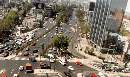
Photograph Credit and Copyright: Francisco Mier, 1999 Figure 94. Displaced left turn at a continuous flow intersection.(151) The complete CFI design operates as a set of two-phase signals. As part of the first phase, traffic is permitted to enter the left-turn bay by crossing the oncoming traffic lanes during the signal phase serving cross-street traffic. The second signal phase, which
Figure 95. Signal phasing of a continuous flow intersection.(adapted from 150) Intersections with high through and left-turn volumes may be appropriate sites for continuous flow intersections. There should be a low U-turn demand because U-turns are restricted with this design. Right-of-way adjacent to the intersection is needed for the left-turn ramps. Left-turning vehicles make more stops than at conventional intersections, and may experience a slightly higher delay. Through traffic benefits greatly from this design. Safety PerformanceSafety improvements may be experienced by the left-turn movement due to the relocation of the turn lane; rear-end crashes with through vehicles may be reduced. Congestion-related collisions (mainly rear ends) may also decrease if stop-and-go conditions occur less often. Table 77 shows the number of conflict points at a four-leg signalized intersection as compared to a continuous flow intersection. The number of merging/diverging conflict points is the same at a continuous flow intersection as compared to a conventional four-leg signalized intersection. All left-turn (crossing) conflicts are removed. However, the number of angle (crossing) conflicts would triple. Figure 96 shows the conflict point diagram for a continuous flow intersection. Table 77. Number of conflict points at a four-leg signalized intersection compared to a continuous flow intersection with displaced left turns on the major street only.
Figure 96. Conflict diagram for a continuous flow intersection with displaced left turns on the major street only. Table 78 summarizes the expert opinion of the authors with regard to the safety benefits of changing a four-leg signalized intersection to a CFI. Table 78. Safety benefits of converting a four-leg signalized intersection to a CFI: Expert opinion.
Operational PerformanceThe key operational benefit of this intersection is that multiphase signal operation is not required to provide protected left-turn movements. This benefits through traffic. Continuous flow intersections provide an at-grade intersection solution that can improve traffic operations beyond the capabilities of other conventional at-grade solutions.(152) Jagannathan and bared evaluated three different CFI configurations (four-leg intersection with displaced left on all approaches; four-leg intersection with displaced left on two approaches; and t intersection with displaced left on one approach) against a conventional intersection for a range of high entering volumes using VISSIM.(150) Operational benefits of the CFI were realized for all three CFI intersection configurations. For the case of the four-leg intersection with displaced left turns on all approaches, the following findings were documented:
Goldblatt, Mier, and Friedman evaluated the performance of traffic at CFI designs by comparing it with the performance of conventional intersections under multiphase signal control.(152) Traffic demand was assumed equal on each approach leg to the intersection and turn movements were also assumed equal on each approach (15 percent left turns, 11 percent right turns). Traffic demand volumes for each approach were examined at 1,500, 2,000, and 3,000 vehicles per hour (veh/h). Key findings are as follows:
In 1994 (the date of publication of Goldblatt, Mier, and Friedman), no known CFIs had been constructed.(152) Conclusions were drawn solely from operational simulation modeling. Actual operational experience with CFIs are not widely available, but should become more so as more CFIs are built and evaluated. Abramson, Bergen, and Goldbatt also note the potential for improved arterial performance with CFIs.(153) Because left-turn signal phasing is effectively removed with a CFI, expanded green bands along the arterial can be achieved. Simulation studies using a range of intersection configurations (number of through lanes on the major and minor street) and volumes from intersections in Virginia and North Carolina suggest mixed results in overall travel time through the intersection when compared to a conventional intersection: -1 to +25 percent during off-peak conditions, and -12 to +27 percent during peak conditions. The studies also show a general increase in the overall percent of stops when compared to a conventional intersection: +21 to +87 percent during off-peak conditions, and +12 to +49 percent during peak conditions.(145) Multimodal impactsPedestrian safety is improved with the CFI design, according to Goldblatt et al.(152) Pedestrians cross at times when there are no conflicts with turning vehicles. Pedestrians do require two sequential signal phases to complete a street crossing. However, the layout and operation of the intersection may not be immediately apparent to pedestrians, particularly those with visual disabilities. As a result, pedestrians with visual disabilities may have challenges in way-finding through the intersection. The unconventional flows of vehicles will disrupt the audible cues that visually impaired pedestrians use; therefore, accessible pedestrian signals should be considered for use with this intersection configuration. Physical ImpactsThe footprint of a continuous flow intersection is greater than that of a conventional intersection because it requires right-turn lanes and acceleration lanes in each quadrant. It takes less space than an interchange, however. Socioeconomic ImpactsAccording to Goldblatt et al., the construction cost of a CFI may be two to three times the cost of a standard intersection design due to increased right-of-way costs, and the need for additional, coordinated signal controllers.(152) Enforcement, Education, and maintenanceAdditional potential roadblocks to continuous flow intersections include:
a public information campaign may be needed to educate drivers on the operation of the intersection. Abramson, Bergen, and Goldblatt provide a summary of a human factors study of continuous flow intersection operations.(153) Survey questionnaires were used to assess the learning curve of drivers utilizing a CFI in New York. Results indicated a positive response rate of 80 percent for first-time users of the design. After about a week of use, 100 percent of daily drivers expressed positive comments about the design. The basic conclusion is that unfamiliar drivers easily negotiate the intersection form and, after a short break-in period, nearly all drivers can become familiar and comfortable with the design. Key negative comments received in the survey dealt with adequate advance signing that must be provided. The authors detail the experience with one intersection only (and only one leg of the intersection had been designed as a CFI). The use of extensive special directional signing is key to maximizing driver understanding and acceptance. SummaryTable 79 summarizes the issues associated with CFI. Table 79. Summary of issues for continuous flow intersections.
10.2.4 Quadrant Roadway intersectionA quadrant roadway intersection includes an extra roadway between two legs of the intersection (see figure 97). Drivers who wish to turn left from either the major or minor road will travel further to do so, but all left turns will be removed from the main intersection, as shown in figure 98. This design creates two additional intersections, which operate as three-phase signals, but the signal at the main intersection can operate as a two-phase signal, as shown in figure 99. The signals at the quadrant ramps should be located a sufficient distance upstream of the main intersection to eliminate the potential for queue spillback. Reid identified a length of 150 m (500 ft) for his CORSIM evaluation.(154)
Figure 97. Diagram of a quadrant roadway intersection.(adapted from 145)
Figure 98. Vehicular movements at a quadrant roadway intersection.(adapted from 145)
Figure 99. Signal phasing of a quadrant roadway intersection.(adapted from 141) Applicability Intersections of roadways with high through and turn movements may benefit from a quadrant roadway intersection design. If protected left turns at the main intersection are not necessary, more green time can be allocated to the through movements. This application can be useful where right-of- way is limited and there is an existing bypass street on any of the quadrants. Safety Performance Table 80 shows the number of conflict points at a four-leg signalized intersection as compared to a four-leg signalized intersection with a quadrant roadway. The number of merging/diverging conflict points would increase when a quadrant roadway is added. However, the number of crossing (left-turn) conflicts would decrease, provided that midblock restrictions are implemented at the original signalized intersection. Figure 100 shows the conflict point diagram for a four-leg signalized intersection with a quadrant roadway. Table 80. Number of conflict points at a four-leg signalized intersection compared to a four-leg signalized intersection with a quadrant roadway
Figure 100. Conflict point diagram for four-leg signalized intersection with quadrant roadway. Table 81 summarizes the expert opinion of the authors with regard to the safety benefits of adding a quadrant roadway to a four-leg signalized intersection. Table 81. Safety benefits of adding a quadrant roadway to a four-leg signalized intersection: Expert opinion.
Operational PerformanceCompared with conventional intersections, quadrant roadway intersections have less total intersection delay and less queuing. There are conflict points at the primary intersection, which may result in lower crash rates for left-turn- and head-on-related crashes. The potential for driver confusion at these intersections is greater than that for conventional intersections, as it is with any alternative design. This can be addressed with advance signing. A study that compared simulation of a quadrant roadway intersection with a conventional intersection showed a 22-percent reduction in system travel time. It is important that signals at these intersections be fully coordinated. The quadrant roadway intersection performed best under higher volumes.(141) Simulation studies using a range of intersection configurations (number of through lanes on the major and minor street) and volumes from intersections in Virginia and North Carolina suggest a reduction in overall travel time through the intersection when compared to a conventional intersection: -21 to +1 percent during off-peak conditions, and -21 to -1 percent during peak conditions. The studies also show a general increase in the overall percent of stops when compared to a conventional intersection: -12 to +96 percent during off-peak conditions, and -3 to +33 percent during peak conditions.(145) SummaryTable 82 summarizes the issues associated with quadrant roadways. Table 82. Summary of issues for quadrant roadways.
10.2.5 Super-Street Median CrossoverThe super-street median crossover improves operation of the main road through maneuver, and also reduces delay for left turns off the major road. DescriptionThe super-street median crossover design, shown in figure 101, is similar to the median U-turn crossover in that an indirect maneuver is accomplished with a U-turn in the median. With a super-street median crossover, crossroad drivers cannot proceed straight through the intersection, as can be seen in figure 102. A through movement is accomplished by turning right onto the major road, turning left through the crossover, and turning right again back onto the minor road. Also, as with the median U-turn design, drivers are not able to turn left from the crossroad onto the major road, and a median U-turn is used to accomplish the left-turn maneuver. Left turns from the major road are direct.
Figure 101. Illustration of super-street median crossover.(adapted from 155)
Figure 102. Vehicular movements at a super-street median crossover. The design of a super-street median crossover is similar to that of a median U-turn crossover. Crossovers should be located approximately 180 m (600 ft) from the main intersection. A semi-trailer combination design vehicle would need a median width of 18 m (60 ft) to accommodate a U-turn. Additional right-of-way would not be required to construct this treatment where the major streets already have a wide median. Two two-phase traffic signals are required at the main intersection-one for each minor street approach. Because no minor street through or left-turn movements are allowed, these two signals can operate independently with different signal cycle lengths, if desired. A typical phasing diagram is shown in figure 103, which shows the phasing for each of the two-phase signals on each half of the intersection. In addition, a traffic signal may be needed at each of the upstream median crossover locations; these signals would also have only two phases. Because the two halves of the intersection operate independently, it is possible to achieve a maximum amount of traffic progression in both directions along the major street. There are fewer conflict points with this intersection design than with conventional intersections. Though this design may cause confusion for pedestrians, there is less opportunity for conflicts with vehicles. The crossing is a two-stage process. This design is appropriate in situations where there are high through volumes on the major road but only relatively low volumes of through traffic on the cross road, since this through movement is interrupted. For crossroads with higher through volumes, offset super-street crossover design can be used. With this design, the approaches on the crossroad are offset, and are at the same location as the median crossovers. This allows minor road through vehicles to proceed straight from the crossover to the crossroad without turning.
Figure 103. Signal phasing of a super-street median crossover. Safety PerformanceTable 83 shows the number of conflict points at a four-leg signalized intersection as compared to a super-street median crossover. The number of left-turn crossing conflicts would be reduced to two at a super-street median crossover. No crossing (angle) conflict points exist at a super-street median crossover. Figure 104 shows the conflict point diagram for a super-street median crossover. Table 83. Number of conflict points at a four-leg signalized intersection compared to a super-street median crossover.
Figure 104. Conflict diagram for a super-street median crossover. Table 84 summarizes the expert opinion of the authors with regard to the safety benefits of changing a four-leg signalized intersection to a super-street median crossover. Table 84. Safety benefits of converting a four-leg signalized intersection to a super-street median crossover: Expert opinion.
Operational PerformanceThis design can result in more stops for through vehicles than other designs. It also creates out-of-direction travel for cross street through and left-turn movements, which limits their capacity and increases their travel times. Left turns from the major road experience less delay, however. Simulation studies using a range of intersection configurations (number of through lanes on the major and minor street) and volumes from intersections in Virginia and North Carolina suggest mixed results in overall travel time through the intersection when compared to a conventional intersection: -8 to +18 percent during off-peak conditions, and -10 to +71 percent during peak conditions. The studies also show a substantial increase in the overall percent of stops when compared to a conventional intersection: -8 to +187 percent during off-peak conditions, and +16 to +146 percent during peak conditions.(145) A study of a Michigan corridor comparing TWLTL to median U-turn crossovers also looked at super-street median crossovers. The study showed that during peak hours, travel time on the corridor with super-street median crossovers decreased by 10 percent; average speed was 15 percent higher than in the same corridor with a TWLTL. In nonpeak hours, the super-street median crossovers had the same efficiency as the TWLTL, even though a higher delay for left-turning vehicles had been expected due to the higher travel distance for a vehicle to turn left using a median crossover.(149) While travel time and delay will increase for cross street through and left-turn traffic, the major road through and left-turn movements will experience an improvement in intersection operations. Driver opinions and acceptance of the intersection design may vary according to which maneuver a driver typically makes at the intersection. Enforcement, Education, and maintenanceSuper-street median crossovers have not been constructed in nearly as many locations as median U-turn crossovers. This treatment has not been implemented for an entire corridor. Therefore, opportunities for public response to the crossovers are low. Little enforcement will be needed for this design. It may be necessary to occasionally provide enforcement of traffic control devices at the median crossovers. There is a potential for driver and pedestrian confusion with this design. a public information campaign may be desirable in order to prepare drivers for the opening of the new intersection. Signs guiding drivers through the intersection will be appropriate, especially in areas where super-street median crossovers are not common. SummaryTable 85 summarizes the issues associated with the super-street median crossover. Table 85. Summary of issues for super-street median crossovers.
10.3 Grade separation TreatmentsGrade separation treatments should be considered when at-grade intersection treatments are no longer feasible. Grade separation is costly, has substantial impacts on traffic during construction, and substantially affects pedestrians, bicyclists, and adjacent land uses. Grade separation does provide a significant benefit to the operations of through movements given that conflicts with opposing and adjacent traffic are eliminated. The reduction of conflicts also improves safety performance. The following sections discuss the split intersection and diamond interchange forms. Although the split intersection is an at-grade form, it is a logical intermediate stage to complete grade separation and thus is discussed in this section. 10.3.1 Split intersectionDescriptionA split intersection, shown in figure 105, requires that the major road approaches to an intersection be converted into two one-way streets. Essentially, the split intersection becomes an at-grade diamond configuration. Rather than one intersection that would operate as a four-phase signal (assuming protected left-turn phasing), two intersections are created that can operate as three-phase signals. The split intersection can be a potential "stage" to constructing a diamond (or other) interchange. According to Bared and Kaisar, the split intersection facilitates smoother traffic flows with less delay and also may improve safety by reducing the number of intersection conflict points. (156) ApplicabilityA split intersection may be considered where:
Safety PerformanceAccording to two studies split intersections can have the following safety benefits:(156,157)
However, with the split intersection design, there is the possibility of wrong-way movements.
Figure 105. Illustration of a split intersection.(adapted from 145) Table 86 shows the number of conflict points at a four-leg signalized intersection as compared to a split intersection. A split intersection would have the same number of merging/diverging and crossing (angle) conflict points as a four-leg signalized intersection. However, there are only 6 crossing (left-turn) conflict points at a split intersection, compared to 12 at a four-leg signalized intersection. Figure 106 shows the conflict point diagram for a split intersection. Table 86. Number of conflict points at a four-leg signalized intersection compared to a split intersection.
Figure 106. Conflict point diagram for a split intersection. Table 87 summarizes the expert opinion of the authors with regard to the safety benefits of a conversion of a four-leg signalized intersection to a split intersection. Table 87. Safety benefits of converting a four-leg signalized intersection to a split intersection: Expert opinion.
Operational PerformanceConversion to a split intersection (versus a standard intersection) can result in substantial increases in effective green time available to traffic.(157) This increase becomes even larger when the percentage of left-turning traffic rises. The minimum recommended spacing is 50 m (165 ft) and increases as a function of signal cycle length and left-turning volume. Bared and Kaisar performed a traffic simulation (using CORSIM) to compare a standard four-leg intersection and a split intersection.(156) Optimum traffic signal timing plans for both intersection configurations were developed using pASSER©. Results of the CORSIM analysis reveal that the split intersection is able to handle higher traffic volumes with less delay per vehicle than is a single intersection. As the entering volume and proportion of left-turning vehicles increases, the advantage of the split intersection relative to the standard intersection increases (in terms of reducing delay). Average delays for both intersections are similar for intersections with a total entering flow of 4,000 veh/h and less. At higher entering volumes (5,000 to 6,000 veh/h), the reduction in delay with a split intersection was on the order of 40 to 50 percent. This increases as the percent of left-turning traffic increases from 15 to 30 percent of the total traffic. A limited number of split intersections have been constructed (none known in the United States). As such, operational experience with split intersections is limited. Operational experience and public response to one constructed in israel has been positive.(156) Other split intersections in israel have been converted to grade-separated interchanges. The majority of conclusions regarding split intersections have been gained from computer simulation runs of anticipated traffic operations. Simulation studies using a range of intersection configurations (number of through lanes on the major and minor street) and volumes from intersections in Virginia and North Carolina suggest a general reduction in overall travel time through the intersection when compared to a conventional intersection: -20 to -8 percent during off-peak conditions, and -15 to +9 percent during peak conditions. The studies also show an increase in the overall percent of stops when compared to a conventional intersection: +21 to +87 percent during off-peak conditions, and +12 to +49 percent during peak conditions.(145) Split intersections can have the following operational benefits:(156,157)
Operational liabilities are the likelihood that the design will require two stops (versus one) in a poorly coordinated system. Multimodal ImpactsAt split intersections, pedestrian crossing distances (for the cross street) are significantly reduced. Because these types of intersections have the look and feel of a grade-separated interchange, pedestrians may find them intimidating, and motorists may be less aware of pedestrians' presence. Physical ImpactsThese types of intersections would have a high initial construction cost yet provide a preliminary stage to eventual grade separation. Socioeconomic ImpactsA split intersection would have additional right-of-way requirements. SummaryTable 88 summarizes the issues associated with constructing a split intersection. Table 88. Summary of issues for split intersections.
10.3.2 Diamond InterchangeDescriptionA diamond interchange is a treatment where the through movements on the major street are physically separated from the other turning movements, which are typically served by one or two intersections (ramp terminals) on the minor street. On- and off-ramps connect the major street to these ramp terminals, forming the shape of a diamond. Diamond interchanges have a variety of forms, and their function depends on the separation between the two ramp terminals and the associated traffic control strategy. Two of the more common types of diamond interchanges used in constrained urban environments are the single-point diamond and compressed diamond. Additional information on other interchange forms can be found in the AASHTO policy.(3) A single-point diamond interchange (also referred to as a single-point urban interchange, or SPUI, although these interchanges are not inherently restricted to urban environments) operates as a single signalized intersection. Left turns from the ramps and on the cross street are aligned such that they oppose each other, eliminating a potential source of conflict. Because of the layout of the interchange, at-grade movements are served by a three-phase signal, although relatively long cycle lengths are typical. This is in part due to the fact that longer clearance intervals are required for a single-point interchange to allow vehicles to depart the intersection. Figure 107 shows a typical single-point interchange.
Figure 107. Diagram of a single-point interchange.(adapted from 158) A compressed diamond interchange (also referred to as a tight diamond interchange) operates as two closely spaced intersections, typically controlled by four-phase overlap signal phasing system for the two intersections. Layout of the left turns on the cross street are back to back, resulting in an increased cross section across/under the bridge relative to a single-point interchange. Even with this increased cross section, there is less open pavement area at a compressed diamond interchange relative to a single-point interchange, which allows for shorter clearance intervals. Figure 108 shows a typical compressed diamond interchange.
Figure 108. Diagram of a compressed diamond interchange.(adapted from 158) A single-point interchange can operate with three or four phases; a three-phase signal phasing scheme is illustrated in figure 109. As can be noted from the phasing diagram, pedestrian movements across the arterial street or through movements on the ramp (as with frontage roads) cannot be accommodated without adding a fourth phase.
Figure 109. Typical signal phasing of a single-point interchange. The compressed diamond interchange can operate with three or four phases; a four-phase signal phasing scheme is illustrated in figure 110. The figure shows the coordinated operation of the signals on each side of the interchange. This phasing scheme can accommodate pedestrians in all directions.
Figure 110. Typical signal phasing of a compressed diamond interchange. ApplicabilityInconsistent findings relating to the single-point and compressed diamond interchange forms relate primarily to the operational and safety performance of each form. As analysis procedures and site conditions differ for each interchange application, it is difficult to draw firm conclusions regarding the merits of a particular interchange form without appropriately studying the specific conditions of a site. Safety PerformanceSafety information on the single-point interchange is limited. Smith and Garber report some safety findings, but indicate the findings may be more representative of changing design details than of true safety differences.(159) Leisch, Urbanik, and Oxley suggest that the potential for higher crash experience is present at single-point interchanges because of the large, uncontrolled pavement area and the opposing left turns.(160) No crash data are provided, however. Smith and Garber report that driver unfamiliarity with the new single-point interchange design was not a major factor in crash occurrence at the interchange, although there were complaints of confusion at single-point interchanges shortly after it was opened.(159) Rear-end crashes on the off-ramp were the predominant crash type. A study by Messer et al. indicated that the single-point interchange design does not lead to a higher number of crashes than found in a typical at-grade intersection.(161) Table 89 shows the number of conflict points at a four-leg signalized intersection as compared to a compressed diamond and single-point diamond interchange. The compressed diamond interchange would have a greater number of merging/diverging conflict points as compared to a four-leg signalized intersection. Both the compressed diamond and single-point diamond interchange would have fewer crossing (left-turn) conflict points. The single-point diamond interchange would have no crossing (angle) conflict points. Figures 111 and 112 show the conflict point diagrams for a single-point diamond and compressed diamond interchange, respectively. Table 90 summarizes the expert opinion of the authors with regard to the safety benefits of a conversion of a four-leg signalized intersection to a compressed diamond and single-point diamond interchange. Table 89. Number of conflict points at a four-leg signalized intersection compared to a compressed diamond and single-point diamond interchange.
Figure 111. Single-point diamond interchange conflict point diagram.
Figure 112. Compressed diamond interchange conflict point diagram. Table 90. Safety benefits of converting a four-leg signalized intersection to a compressed diamond and single-point diamond interchange: Expert opinion.
Operational PerformanceWith regard to the single-point interchange, left turns off the cross street are typically accommodated at 135-degree angles, while left turns at the ramps are typically 45 to 60 degrees. Because the left turns from the ramps are at a relatively shallow angle, these movements can take place at higher speeds and at higher saturation flow rates relative to a compressed diamond interchange. Saturation flow rates for the left turns from the ramp at a single-point interchange approach those for a through movement.(162) Similar to the single-point interchange, a compressed diamond interchange can be constructed in a relatively confined right-of-way while serving high traffic demand volumes. A more conventional structure can be used to allow future modifications, if needed. In addition, the compressed diamond design can serve pedestrians effectively and work in combination with frontage roads without a substantial decrease in the efficiency of the interchange. A single-point interchange combined with a frontage road would also decrease the overall efficiency of the interchange, as additional phases are required at the signal to serve traffic movements. Operational analyses of the two types of interchanges are mixed, with some studies reporting the single-point interchange as superior to the compressed diamond interchange in most circumstances, some reporting the opposite, and others reporting no significant difference. Several simulation-based studies have been performed that indicate that the single-point interchange performs better than a compressed diamond interchange for many volume scenarios.(158,163) Fowler reports that in most traffic scenarios, the single-point interchange provides more capacity than a compressed diamond interchange and that the capacity of the compressed diamond interchange is more sensitive to traffic volumes than is the single-point interchange.(162) The performance of the compressed diamond interchange improves relative to the single-point interchange when the:
On the other hand, Leisch, Urbanik, and Oxley found that the compressed diamond is more efficient than the single-point interchange for most traffic volume/pattern situations.(160) Bonneson and Lee found similar results when frontage roads are present.(164) Both studies show that the compressed diamond interchange can accommodate a greater variability of traffic patterns than the single-point interchange, and the cycle length requirements are shorter for the compressed diamond than the single-point interchange. Because of these wide variations in recommendations, no simple conclusion regarding operational performance can be made, and case-by-case analysis is therefore recommended. Multimodal ImpactsPedestrian issues are sensitive at a single-point interchange. At a single-point interchange, there is no phase to provide for pedestrian movements. Pedestrians will need two phases to cross the roadway (and require an adequate refuge area). Addition of an exclusive pedestrian phase would decrease the overall efficiency of the interchange. Physical ImpactsAn advantage of the single-point interchange is that the interchange can be constructed in a relatively confined right-of-way while serving high traffic demand volumes. However, deep span lengths are required with both overpass and underpass designs. The structure for a single-point interchange can be more difficult to modify to meet future needs than that for a compressed diamond interchange. Socioeconomic ImpactsThe primary disadvantage of a single-point interchange is the high construction cost of the bridge structure. SummaryTable 91 summarizes the issues associated with constructing a single-point or compressed diamond interchange. Table 91. Summary of issues for single-point and compressed diamond interchanges.
|
||||||||||||||||||||||||||||||||||||||||||||||||||||||||||||||||||||||||||||||||||||||||||||||||||||||||||||||||||||||||||||||||||||||||||||||||||||||||||||||||||||||||||||||||||||||||||||||||||||||||||||||||||||||||||||||||||||||||||||||||||||||||||||||||||||||||||||||||||||||||||||||||||||||||||||||||||||||||||||||||||||||||||||||||||||||||||||||||||||||||||||||||||||||||||||||||||||||||||||||||||||||||||||||||||||||||||||||||||||||||||||||||||