U.S. Department of Transportation
Federal Highway Administration
1200 New Jersey Avenue, SE
Washington, DC 20590
202-366-4000
Federal Highway Administration Research and Technology
Coordinating, Developing, and Delivering Highway Transportation Innovations
 |
| This report is an archived publication and may contain dated technical, contact, and link information |
|
Publication Number: FHWA-HRT-04-094
Date: November 2004 |
||||||||||||||||||||||||||||||||||||||||||||||||||||||||||||||||||||||||||||||||||||||||||||||||||||||||||||||||||||||||||||||||||||||||||||||||||||||||||||||||||||||||||||||||||||||||||||||||||||||||||||||||||||||||||||||||||||||||||||||||||||||||||||||||||||||||||||||||||||||||||||||||||||||||||||||||||||||||||||||||||||||||||||||||||||||||||||||||||||||||||||
Evaluation of LS-DYNA Soil Material Model 147PDF Version (2.87 MB)
PDF files can be viewed with the Acrobat® Reader® CHAPTER 5. DEVELOPER'S RECOMMENDED PARAMETERSThe developer modeled direct shear test 4 (DS-4) using LS-DYNA and prepared a graph of the physical test data compared to the shear stress-deflection curve from LS‑DYNA. This figure and the corresponding input parameters from the developer are shown in figure 15 and table 11, respectively. The LS-DYNA format for these parameters is shown in table 12. 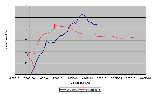 Figure 15. DS-4 simulation results from the developer. Note: Figure 15 is labeled "shear force"; however, it is really shear stress. It is assumed that the shear stress was made by dividing the shear force (the x-direction cross section force defined in the model) by the original cross-sectional area of the sample (0.2 square meters (m2)). Table 11. Revised developer's and baseline material parameters.
These parameters were put into the direct shear model at the user's facility and were simulated. The model became unstable at 38 ms and terminated, as shown in figure 16. The shear stress versus displacement for this run is shown in figure 17. The shear stress calculated on the user's SGI computer was significantly lower than the shear stress calculated by the developer's PC computer. It was then noted that the developer's graph, as shown in figure 15, terminated at approximately 46 mm. Because the loading was at 1 mm/ms and the specified termination time was 50 ms, the direct shear model should have displaced 50 mm. This suggests that the developer's graph is representative of instability occurring in the soil material model as well. 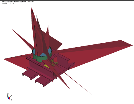 Figure 16. Instability of developer's soil model. 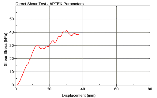 Figure 17. Direct shear results with the developer's soil parameters. CAUSE OF INSTABILITYAs is shown in figure 16, shooting nodes can be seen in the model. It was desired to see which material parameters induced this failure mode. The parameters used are shown in tables 13 and 14. Additionally, the four parameters that were believed to be the source of the instability were altered individually to determine the source of the instability. These parameters and their corresponding LS-DYNA runs are listed in table 15. It appears that the damage routines caused the instability. When Damlev was changed from 1.00 to 0.99, the model became unstable. Since both Damlev and Epsmax must be exceeded in order to delete elements, the instability lies somewhere in the damage algorithms and probably not in the variable input routines. Therefore, it must be the instability with other material parameters, the damage algorithms, and/or the element formulation. Subuently, the developer proposed a probable cause for the instability as follows. In LS-DYNA, an element fails when one of the gauss points reaches the failure criteria. For fully integrated elements (8 gauss points), this causes an early failure. This early failure does not let the internal forces go to zero before the failed elements are eliminated from the calculation. In turn, this leads to very large unbalanced forces at the nodes, causing unstable behavior (shooting nodes). In addition, this analysis is difficult for LS-DYNA to complete with fully integrated elements because of the well-known problems with shear locking of fully integrated elements. Unfortunately, under-integrated elements are not an option because of excessive hourglassingas discussed in chapter 6.
|
||||||||||||||||||||||||||||||||||||||||||||||||||||||||||||||||||||||||||||||||||||||||||||||||||||||||||||||||||||||||||||||||||||||||||||||||||||||||||||||||||||||||||||||||||||||||||||||||||||||||||||||||||||||||||||||||||||||||||||||||||||||||||||||||||||||||||||||||||||||||||||||||||||||||||||||||||||||||||||||||||||||||||||||||||||||||||||||||||||||||||||

