U.S. Department of Transportation
Federal Highway Administration
1200 New Jersey Avenue, SE
Washington, DC 20590
202-366-4000


Skip to content
Facebook iconYouTube iconTwitter iconFlickr iconLinkedInInstagram

Federal Highway Administration Research and Technology
Coordinating, Developing, and Delivering Highway Transportation Innovations

Report
This report is an archived publication and may contain dated technical, contact, and link information
Publication Number: FHWA-HRT-09-039
Date: April 2010

Pavement Marking Demonstration Project: State of Alaska and State of Tennessee-Report to Congress

Appendix C. Durability Test Deck Information

Previous | Table of Contents | Next

Since one of the primary goals of this task was to compare the durability performance of different pavement marking materials measured over time, the markings needed to be subjected to similar traffic conditions. Furthermore, a reasonably high traffic volume was desired in order to illustrate the differences between materials in the short time available for the study. It was important to consider roadway design features, traffic characteristics, and local environmental conditions when selecting the test deck locations. Together with each State transportation department, the study sites were carefully selected so that they were representative and similar. The sites were also chosen based on pavements that would not need major maintenance during the life of the study. All of the test decks were installed on asphalt pavements in good condition; all materials were installed along the edge line and right-most lane line of multilane highways; and all test sections were applied along tangent sections.

Pavement Marking Preparation for In-Laid Markings

The intended goal of the placement of the pavement markings was to place half the length of the marking section on the surface of the road and half in a groove (in-laid). This required that within each test section, half of the section needed the current markings to be eradicated, leaving a clean new surface for installation. The second half of the test section needed to be grooved to an adequate depth so that the marking would be in-laid below the road surface. The specific parameters of the grooving for the in-laid products were based on providing a consistent difference between the height of the final pavement marking system and the height of the roadway. The goal was to have the pavement marking system, including the optics of the pavement marking system, slightly depressed in the roadway to provide protection from the wintertime plowing and studded tires.

The eradication process was not always consistent and ended up leaving a shallow groove in the road surface. A similar problem occurred when trying to create the groove for the in-laid marking section. The grooving machines were typically deeper than specified. To account for these discrepancies in eradication and groove depths, areas where the markings were eradicated were considered to be placed in a shallow groove, and areas where the road was fully grooved (marking system below the road surface) were considered a deep groove. In some cases, markings were also applied over the preexisting markings and were considered a surface application. The various placements of the markings all occurred within the 0.5-mi test section. Markings that only had two placement types were each installed for approximately 0.25 mi.

Anchorage, AK, Pavement Marking Test Deck Area

Figure 20.  Photograph.  Glenn Highway SR-1.  The photograph shows a three-lane cross section of a six-lane divided highway on Glenn Highway, State Route (SR)-1.  The photograph is taken from a driver's perspective from the middle lane in the direction of travel.  There is a yellow edge line on the far left of the three lanes and a white edge line on the far right of the three lanes.  There are also white dashes separating the three lanes from one another.  A truck is in the right lane, and another vehicle is in the center lane.  The opposing traffic is on the left side, separated by a grassy median.

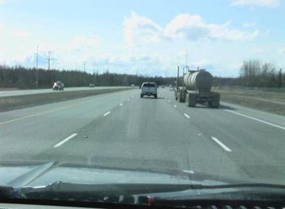
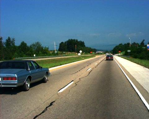
Figure 20. Photo. Glenn Highway SR-1.

Figure 21.  Photograph.  Proposed pavement marking installation sites.  An aerial photograph taken from GoogleTM Earth shows the proposed pavement marking installation sites along Glenn Highway State Route 1 outside Anchorage, AK.  A yellow line indicating the Glenn Highway begins at the bottom left of the photograph and extends to the top right.  Along the illustrated length of the highway, there are nine proposed installation sites marked by circles at the beginning and end point of each site.  The beginning points for Sites 2 through 8 are the same as the end points of the previously numbered sites.

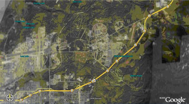
Figure 21. Photo. Proposed pavement marking installation sites.

Figure 22.  Photograph.  Test section 3.  An aerial photograph illustrates the location of test section 3 on the Glenn Highway State Route 1 outside Anchorage, AK.  The testing area is located on a straight section of the highway, which runs left to right in the photograph, with the northbound lanes on the bottom.  There is an interchange with Turpin Road and the northbound lanes of the Glenn Highway at the midpoint of the test section.  The test section is approximately 0.5 mi long.

Figure 22. Photo. Test section 3.

Figure 23.  Photograph.  Test section 5.  An aerial photograph illustrates the location of test section 5 on the Glenn Highway State Route 1 outside Anchorage, AK.  The testing area is located on a straight section of the highway.  There is an interchange with Arctic Valley Road approximately 0.2 mi beyond the test section at the top of the photograph.  The test section is approximately 0.5 mi long.

Figure 23. Photo. Test section 5.

Figure 24.  Photograph.  Test section 6.  An aerial photograph illustrates the location of test section 6 on the Glenn Highway State Route 1 outside Anchorage, AK.  The testing area is located on a straight section of the highway.  There is an interchange with Arctic Valley Road immediately before the beginning of the test section at the bottom of the photograph.  The test section is approximately 0.5 mi long.

Figure 24. Photo. Test section 6.

Figure 25.  Photograph.  Test section 7.  An aerial photograph illustrates the location of test section 7 on the Glenn Highway State Route 1 outside Anchorage, AK.  The testing area is located on a straight section of the highway.  There is an interchange with D Street approximately 0.1 mi beyond the test section at the top of the photograph.  The test section is approximately 0.5 mi long.

Figure 25. Photo. Test section 7.

Section 8 Test Area

Figure 26.  Photograph.  Test section 8.  An aerial photograph illustrates the location of test section 8 on the Glenn Highway State Route 1 outside Anchorage, AK.  The testing area is located on a straight section of the highway.  The highway begins to curve to the left immediately beyond the end of the test section at the top of the photograph.  The test section is approximately 0.5 mi long.

Figure 26. Photo. Test section 8.

Figure 27.  Photograph.  Test section 9.  An aerial photograph illustrates the location of test section 9 on the Glenn Highway State Route 1 outside Anchorage, AK.  The testing area is located on a straight section of the highway immediately after a right hand curve at the left, bottom corner of the photograph.  The test section is approximately 0.5 mi long.

Figure 27. Photo. Test sections 9.

Anchorage, AK, Pavement Markings

Table 35. Initially installed edge line and outside lane line pavement markings (8/7/06).

Test Section Marking Type Application Type Placement (In-Laid) Groove Depth (mil) Material Thickness (mil) Bead Type
1 AK a
Alaska DOT&PF low VOC paint
Spray
Surface, (Shallow), (Deep)
0, 65, 160 12
AASHTO M247
2 AK a
3M all weather paint
Spray
(Shallow), (Deep)
65, 160 30
Swarco type 2 and 3M elements
3 AK a
MMA 98:2 (Stirling Lloyd)
Extruded
(Shallow), (Deep)
70, 175 100
Type 2
4 AK a
MMA 98:2 (Stirling Lloyd)
Agglomerate
(Shallow), (Deep)
90, 275 200
Type 2
5 AK a
3M pavement marking tape 380IES
Rolled
(Deep)
175 100
N/A

5 AK b

3M pavement marking tape 380WR
Rolled
(Deep)
175 100
N/A
6 AK a
MMA 4:1 (Ennis)
Extruded
(Shallow), (Deep)
60, 120 100
30/50 Mesh Swarco Megalux T13 coated
6 AK b
Modified urethane (IPS)
Spray
Surface, (Shallow), (Deep)
0, 70, 120 20
Potters Type 1 AC110 coating and type 4 Visibead plus 2
7 AK a
Low temperature acrylic waterborne paint (Ennis)
Spray
Surface, (Shallow), (Deep)
0, 140, 175 12
Swarco AASHTO M247
8 AK a
MMA 4:1 (Degussa–Pathfinder™)
Agglomerate
(Shallow), (Deep)
120, 320 200
Swarco AASHTO M247
9 AK a
High build acrylic waterborne paint (Ennis)
Spray
(Shallow), (Deep)
60, 145 30
Swarco Megalux Type 3
10 AK a
Polyurea (IPS)
Spray
(Shallow), (Deep)
65, 155 20
Potters type 1 AC110 coating and type 4 Visibead plus 2

N/A = Not applicable.

Note: Section 1 AK a was applied with long-line striping equipment; all other sections were hand cart applied.

Table 36. Pavement markings installed after the first winter in Anchorage, AK.

Date Test Section Marking Type Application Type Placement (In-Laid) Groove Depth (mil) Material Thickness (mil) Bead Type
6/21/07 All Alaska DOT low VOC paint Spray Over existing
Existing
12
AASHTO M247
9/24/07 1 AK b Flint trading premark preformed thermoplastic Heat in place (Deep)
160
125
N/A
10/2/07 2 AK b Standard Alaska DOT&PF MMA Spray (Shallow), (Deep)
85, 180
60
AASHTO M247

N/A = Not applicable.

Note: Paint and MMA were applied with long-line striping equipment; preformed thermoplastic was hand cart applied.

Table 37. Pavement markings installed after the second winter in Anchorage, AK.

Date Test Section Marking Type Application Type Placement (In-Laid) Groove Depth (mil) Material Thickness (mil) Bead Type
8/5/08 9 AK b MMA (Ennis), paint (Pervo) Extruded with raised edges, double spray (Shallow), (Shallow and Deep)
60, 60 and 145
100, 40
30/50 Mesh, 30–30–40 Swarco mega blend
8/5/08 7 AK b MMA (Ennis), paint (Pervo) Extruded with raised edges, spray (Deep)
175
100, 20
30/50 Mesh, 30–30–40 Swarco mega blend

Note: Paint was applied with long-line striping equipment; MMA was hand cart applied.

Nashville, TN, Pavement Marking Test Deck Area

Figure 28.  Photograph.  SR-840.  The photograph shows the divided highway on State Route (SR)-840 near Nashville, TN, on which one of the pavement marking test decks was installed.  Each direction of travel has two lanes.  The photograph is taken from the driver's perspective from the right lane.  There is a yellow edge line on the left of the two lanes and a white edge line on the right of the two lanes.  Also, there are white dashed lines separating the two lanes.  The lanes in the opposing direction with one car are to the left, separated by a grassy median.

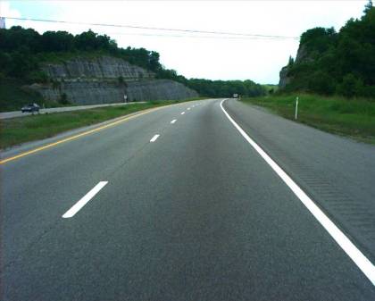
Figure 28. Photo. SR-840.

Figure 29.  Illustration.  Proposed pavement marking installation sites.  A regional map shows a section of State Route 840 in Tennessee between I-24 to the east and I-65 to the west.  The diagram indicates the proposed locations of the pavement marking installations.  The sections are noted as follows:  section 1 eastbound (EB) rumble stripes, section 2 EB, section 4 EB, section 5 EB, section 1 westbound (WB), section 2 WB, section 3 WB, section 4 WB, and section 5 WB.  For a given section number, the EB and WB installations are along the same section of the highway.

Figure 29. Illustration. Proposed pavement marking installation sites.

Figure 30.  Illustration.  Test sections 1 and 2.  A local map shows test sections 1 and 2 along State Route 840 near Nashville, TN.  The section descriptions are noted as follows:  section 1 eastbound (EB) starts at the end of bridge, stops at the beginning of point of curvature (left curve), and includes approximately 67 skip lines; section 2 EB starts at the end of guardrail prior to guide sign (guide sign reads Exit 34, Peytonsville Road, 1 mile), stops at the beginning of next guardrail, and includes approximately 75 skip lines; section 1 westbound (WB) starts at the end of the guardrail next to guide sign (guide sign reads Exit 31, IH 65, Nashville, Huntsville, 1 mile), stops at the beginning of the guardrail prior to bridge, and includes approximately 74 skip lines; section 2 WB starts at the end of guardrail after the Exit 35 on-ramp, stops at the beginning of the third guardrail after the on-ramp, and includes approximately 75 skip lines.

Figure 30. Illustration. Test sections 1 and 2.

Figure 31.  Illustration.  Test section 3.  A local map shows test section 3 along State Route 840 near Nashville, TN.  The section description indicates that section 3 westbound (WB) starts at 5 skips prior to guide sign (guide sign reads Exit 34, Peytonsville Road, 1/2 mile), stops at milepost 35, and includes approximately 74 skip lines.

Figure 31. Illustration. Test section 3.

Figure 32.  Illustration.  Test sections 4 and 5.  A local map shows test sections 4 and 5 along State Route 840 near Nashville, TN.  The section descriptions indicate that section 4 eastbound (EB) starts approximately 6 skip lines prior to the State park sign (State park sign reads Exit 42, Henry Horton State Park), stops at milepost 41 (prior to pavement change), and includes approximately 67 skip lines; section 5 EB starts at milepost 43, stops at the beginning of the guardrail after the bridge, and includes approximately 67 skip lines; section 4 westbound (WB) starts at milepost 41, stops at the beginning of the point of curvature for a right curve and includes approximately 67 skip lines; section 5 WB starts at end of guardrail after milepost 44, stops at milepost 43, and includes approximately 67 skip lines.

Figure 32. Illustration. Test sections 4 and 5.

Nashville, TN, Pavement Markings

Table 38. Initially installed edge line and lane line pavement markings in Nashville, TN.

Test Section Marking Type Application Type Placement (In-Laid) Groove Depth (mil) Material Thickness (mil) Bead Type Bead Rate
1 TN-N Thermoplastic (Ennis) Spray Over rumble strip edge line only
N/A
40
Potters type 1 AC110 coating 8 lb/100 ft2
2 TN-N Thermoplastic (Ennis) Spray (Shallow), (Deep)
75, 185
40
Potters type 1 AC110 coating 8 lb/100 ft2
3 TN-N Thermoplastic (Ennis) Spray (Shallow), (Deep)
85, 270
90
Potters type 1 AC110 coating 8 lb/100 ft2
4 TN-N Thermoplastic (Ennis) Extruded (Shallow), (Deep)
95, 180
120
Potters type 1 AC110 coating and type 4 Visibead plus 2 6 lb type 1 and 10 lb Type 4 per 100 ft2
5 TN-N Thermoplastic (Gulfline) Inverted Profile (Shallow)
75
50/225
Potters type 1 AC110 coating and type 4 Visibead plus 2 6 lb Type 1 and 10 lb Type 4 per 100 ft2
6 TN-N Low temperature acrylic waterborne paint (Ennis) Spray (Shallow), (Deep)
55, 145
12
Potters Type 1 AC110 coating 8 lb/100 ft2
7 TN-N Polyurea (Epoplex) Spray (Shallow), (Deep)
110, 165
20
Prismo high index cluster and Potters type 4 Visibead plus 2 8 lb cluster and 10 lb Type 4 per gallon
8 TN-N 3M all weather paint Spray (Shallow), (Deep)
135, 175
26
Swarco type 2 and 3M elements 18 grams type 2 and 7.5 grams elements per linear foot
9 TN-N High build acrylic waterborne paint (Ennis) Spray (Shallow), (Deep)
100, 175
25
Swarco type 3 virgin glass 10-12 lb/100 ft2

Note: All pavement markings were installed with long-line striping equipment.


Table 39. Lead-free thermoplastic pavement markings installed 6/5/08 in Nashville, TN.

Test Section Marking Type Application Type Placement (In-Laid) Groove Depth (mil) Material Thickness (mil) Bead Type Bead Rate
10 TN-N Ennis lead-free thermoplastic Extruded Surface
0
80
AASHOT M247 with AC110 coating 8–10 lb/100 ft2
11 TN-N Swarco lead-free thermoplastic Extruded Surface
0
80
AASHOT M247 with AC110 coating 8–10 lb/100 ft2
12 TN-N Dobco lead-free thermoplastic Extruded Surface
0
85
AASHOT M247 with AC110 coating 8–10 lb/100 ft2

Note: All pavement markings were installed with long-line striping equipment.

Tusculum, TN, Pavement Marking Test Deck Area

Figure 33.  Photograph.  SR-34.  The photograph shows the divided highway on State Route (SR)-34 near Tusculum, TN, along which one of the pavement marking test decks was installed.  Each direction of travel has two lanes.  The photograph is taken from the driver’s perspective from the right lane.  There is a yellow edge line on the left of the two lanes and a white edge line on the right of the two lanes.  Also, there are white dashed lines separating the two lanes.  There is a car in the right lane ahead of the observer’s vehicle, and a car in the left lane that has just passed the observer’s vehicle.  The lanes in the opposing direction can be seen on the left, separated by a grassy median.

Figure 33. Photo. SR-34.

Figure 34.  Illustration.  Proposed pavement marking installation sites.  A regional map shows a section of State Route 34 in Tennessee between Highway 321 to the southwest and the Davey Crockett Birthplace State Park to the northeast.  The diagram indicates the proposed locations of the pavement marking installations.  The sections show section 1 eastbound (EB), section 2 EB, section 3 EB, section 4 EB, section 1 westbound (WB), section 2 WB, and section 3 WB.  For a given section number, the EB and WB installations are along the same section of the highway.

Figure 34. Illustration. Proposed pavement marking installation sites.

Figure 35.  Illustration.  Test section 1.  The section descriptions show that section 1 eastbound starts at the end of the guardrail after the intersection with Chuckey Highway, stops at the end of the edge line at Faulkner Road, and includes approximately 67 skip lines; section 1 westbound starts at the intersection with Faulkner Road, stops at the intersection with Chuckey Highway, and includes approximately 67 skip lines.

Figure 35. Illustration. Test section 1.

Figure 36.  Illustration.  Test section 2.  The section descriptions show that section 2 eastbound starts at the entrance to the U.S. Post Office after the intersection with South Chuckey Ruritan Road, stops at the point of curvature for a right curve with guardrail, and includes approximately 67 skip lines; section 2 westbound starts at the point of treatment (left curve), stops at the beginning of the guardrail prior to intersection with Old State Road (South Chuckey Ruritan Road), and includes approximately 67 skip lines.

Figure 36. Illustration. Test section 2.

Figure 37.  Illustration.  Test sections 3 and 4.  The section descriptions show that section 3 eastbound (EB) starts at the beginning edge line after the intersection with Grant Road, stops at the beginning of the point of curvature  for a right curve with guardrail, and includes approximately 50 skip lines; section 4 EB a starts at the beginning of the point of treatment  for a right curve, stops at the end of the edge line prior to South Oakdale Drive, and includes approximately 33 skip lines; section 4 EB b starts at the beginning edge line after South Oakdale Drive, stops at the beginning of the point of curvature for a left curve, and includes approximately 33 skip lines; section 3 WB starts at the beginning of the point of treatment for a left curve after South Oakdale Drive, stops prior to the intersection with Grant Road, and includes approximately 50 skip lines.

Figure 37. Illustration. Test section 3 and 4.

Tusculum, TN, Pavement Markings

Table 40. Initially installed edge line and lane line markings on 5/14/07.

Test Section Marking Type Application Type Placement (In-Laid) Groove Depth (mil) Material Thickness (mil) Bead Type Bead Rate
1 TN-T Modified epoxy (Epoplex) Spray (Shallow), (Deep)
100, 125
22
Type 4 Visibead Plus II=E16, type 1 MNDOT spec 10-lb type 4 and 6-lb type 1 per 100 ft2
2 TN-T a MMA (Degussa) Extruded (Shallow), (Deep)
100, 170
90
Swarco AASHTO M247 8–10 lb/100 ft2
2 TN-T b MMA (Degussa–Pathfinder™) Agglomerate (Shallow), (Deep)
100, 170
200
Swarco AASHTO M247 8–10 lb/100 ft2
3 TN-T Low-temperature acrylic waterborne paint (Ennis) Spray (Shallow), (Deep)
50, 110
15
AASHTO M247 8 lb/100 ft2
4 TN-T High-build acrylic waterborne paint (Ennis) Spray (Shallow), (Deep)
105, 150
24
Potters type 4 Visibead Plus II 12 lb/100 ft2
5 TN-T a ATM pavement marking tape 300 Rolled (Shallow), (Deep)
60, 130
100
N/A N/A
5 TN-T b ATM pavement marking tape 400 Rolled (Shallow), (Deep)
25, 195
100
N/A N/A
6 TN-T TN standard thermoplastic (superior) Extruded (Shallow), (Deep)
70, 320
90
Swarco AASHTO M247 8–10 lb/100 ft2
7 TN-T Modified urethane (IPS) Spray (Shallow), (Deep)
110, 170
15
Type 4 Visibead Plus II=E16, type 1 MNDOT spec 10-lb type 4 and 8-lb type 1 per 100 ft2

N/A = Not applicable.

Note: Sections 1 TN-T and 6 TN-T were applied with long-line striping equipment; all other sections were hand cart applied.

Previous | Table of Contents | Next

Federal Highway Administration | 1200 New Jersey Avenue, SE | Washington, DC 20590 | 202-366-4000
Turner-Fairbank Highway Research Center | 6300 Georgetown Pike | McLean, VA | 22101