Alternative Intersections/Interchanges: Informational Report (AIIR)
CHAPTER 6. OTHER INTERSECTION CONFIGURATIONS
6.1 ATERNATIVE INTERSECTION CONFIGURATIONS
This chapter briefly identifies alternative intersections (without the same level of detail that has been provided in the previous chapters). Roundabouts are included, although they are becoming more widespread in application throughout the United States. Roundabouts are not covered in detail in this report because they have been covered extensively in other publications.(67, 68)
6.2 ROUNDABOUTS
Roundabouts are a form of intersection control in which the turning movements of the intersection are separated physically by a central island, and the traffic moves along the travel lanes surrounding the central island. Traffic leaves the intersection by executing a right-turn maneuver at the appropriate leg. Roundabouts are popular in many parts of the world. In the United States, there are limited applications, but they are increasing in number as drivers become more familiar with them. Although similar in concept to rotaries and traffic circles, roundabouts are different in geometry and operation. Their differences are highlighted in the FHWA publication, Roundabouts: An Informational Guide.(67) Figure 141 shows the geometry of a typical roundabout, and figure 142 shows a roundabout.
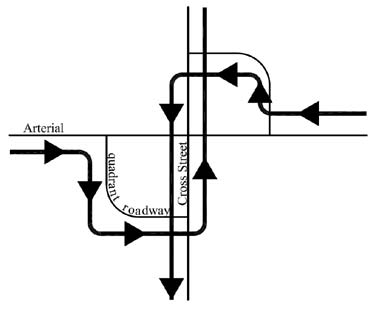
Figure 141. Illustration. Typical geometry of a roundabout.(67)
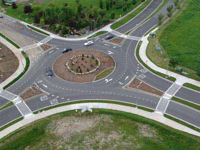
Figure 142. Photo. Typical roundabout.
Methods to determine capacities of single-lane and double-lane roundabouts are outlined in FHWA's Roundabouts: An Informational Guide, and the latest operational findings are documented in NCHRP Report 572.(67,68) Proper signing and marking to provide regulatory and supplemental warning are designed in accordance with MUTCD.(8)
The roundabout informational guide provides detailed recommendations on the design of splitter islands, sight distance, and vertical alignment issues.(67) The NCHRP Synthesis 264, "Modern Roundabout Practice in the United States," details design-related information from several existing sources and design guidelines from Great Britain, France, and Germany.(69) It also includes discussions on roundabout costs and public acceptance. In addition, several States including Florida, Maryland, Oregon, New York, and North Carolina have their own roundabout policies. (See references 70–73.)
6.3 OTHER ALTERNATIVE INTERSECTION CONFIGURATIONS
This section briefly identifies other alternative intersection configurations including the jughandle intersection, the continuous green T-intersection, and the offset T-intersection,
among others.
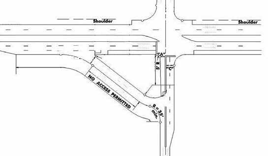
6.3.1 Jughandle Intersection
A jughandle intersection is defined by the NJDOT Roadway Design Manual as an at-grade ramp provided at or between intersections to permit motorists to make indirect left turns and/or U-turns.(74) The typical design of a jughandle intersection is shown in figure 143. An illustration of a typical forward jughandle with the at-grade ramp located prior to the main intersection is shown in figure 144. There are several variants of the jughandle, including the reverse jughandle and the U-turn ramp jughandle.
Source: New Jersey Department of Transportation Roadway Design Manual
Figure 143. Illustration. Typical geometry of a jughandle intersection.(74)
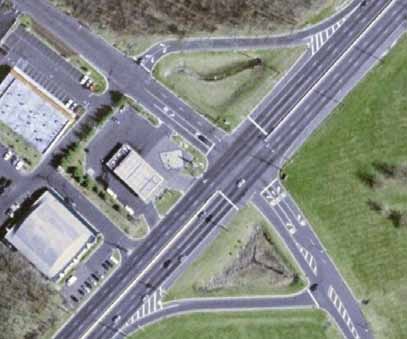
Source: Google™ Earth
Figure 144. Photo. Typical jughandle intersection in New Jersey.
6.3.2 Hamburger or Through-About Intersection
The hamburger or through-about intersection design is a variant of the signalized roundabout. The primary difference is that the mainline through movements are allowed in the intersection. The through and left-turn movements from the minor street are executed by following the circulatory movement around the semicircular islands at the main intersection. This kind of a configuration allows the main intersection to operate on a two-phase signal. The typical configuration is shown in figure 145, and a photograph of a hamburger intersection in Virginia is shown in figure 146.
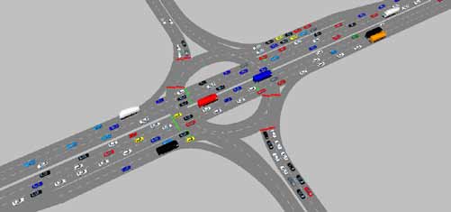
Figure 145. Photo. Typical hamburger intersection movements.(75)
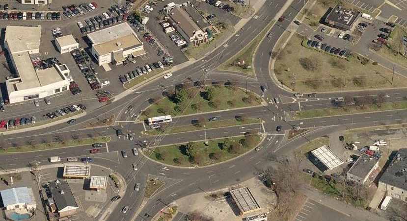
Source: Google™ Earth
Figure 146. Photo. Hamburger intersection in Fairfax, VA.
6.3.3 Synchronized Split-Phasing Intersection
Figure 147 shows vehicular movements in a synchronized split-phasing intersection, which is also known as the double crossover intersection. In this design, which was not found to exist during the preparation of this report, the through and left-turn movements on the mainline cross over before the main intersection. This helps disperse the turning traffic before the main intersection. At the main intersection, the through and the opposing lefts can move concurrently during the same signal phase. This intersection can then operate with two phases. As opposed to the DLT intersection (see chapter 2) where only the left-turning traffic is crossed over, both the through and the left-turn movements are crossed over at the synchronized split-phase intersection.
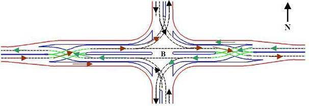
Figure 147. Illustration. Typical synchronized split-phase intersection movements.(76)
6.3.4 Offset T-Intersection
The offset T-intersection is shown in figure 148. It is a variation of the conventional intersection, with the minor street approaches offset by a distance. This lateral separation causes through movements from the minor streets to be diverted to right-turn movements followed by left-turn movements to the other offset minor leg.
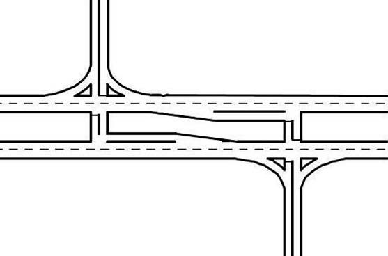
Figure 148. Illustration. Typical geometry of an offset T-intersection.(75)
An offset T-intersection has a total of 22 conflict points, compared to 32 conflict points at a conventional intersection, and can potentially reduce angle collisions. This kind of an intersection is particularly useful in situations where both the major and minor road through volumes are low. Another situation where the offset-T intersection can be appropriate is a retrofit of a skewed intersection with heavy turn volumes and limited through volumes. The design of the offset between the legs of the minor street is dictated by the through and left-turn volumes present at the intersection and sight distance considerations.(75)
6.3.5 Continuous Green T-Intersection
The continuous green T-intersection is shown in figure 149. The basic differences between a continuous green T-intersection and a normal signalized T-intersection is the channelized left-turn movement from the stem of the minor street to the mainline which enables the mainline through movement to be executed at the same time. The signal control at a continuous green
T-intersection operates with three signal phases. The through movement in one direction can flow continuously.
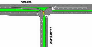
Source: ATTAP, Maryland State Highway Administration
Figure 149. Illustration. Typical geometry of a continuous green T-intersection.(4)
Continuous green T-intersections have been implemented in Florida, Maryland, Virginia, and Michigan. Figure 150 presents an aerial illustration of one in Arlington, VA.
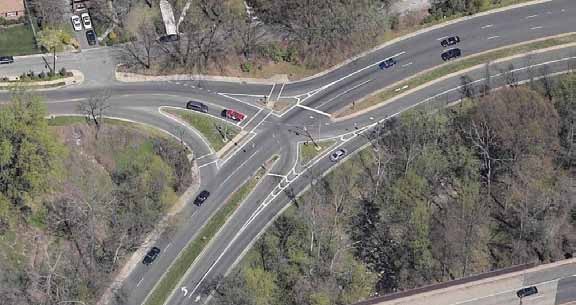
Source: Google™ Earth
Figure 150. Example of a continuous green T-intersection in Arlington, VA.
6.3.6 Parallel Flow Intersection
Several DLT intersections have been constructed in the past decade in the United States, as documented in chapter 2. A variant of the DLT intersection is the parallel flow intersection
or paraflow that is illustrated in figure 151. This design has been patented (U.S. Patent No. 7,135,989) by Quadrant Engineering, LLC.(77)
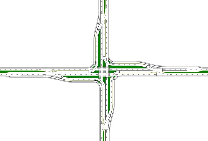
Source: Quadrant Engineering, LLC
Figure 151. Illustration. Typical geometry of a parallel flow intersection.
As in a DLT intersection, the left-turning traffic crosses over opposing through lanes and travel on bypass lanes. The bypass roadway is located parallel to the cross street and merges to the main road at the crossover or bypass. After the left-turn traffic accomplishes the left-turn movement at the main intersection, it merges to the main traffic on the receiving lanes with the help of bypass lanes and the crossover on the receiving approach.(78)
In this design, left-turning traffic faces opposing traffic and signal control at two junctions—the crossover and the main intersection. The main intersection operates under signal control with two phases, and the crossover junctions have coordinated signal control with the main intersection. Figure 152 shows the aerial view of a parallel flow intersection in Oaklyn, NJ. The intersection functions as a partial parallel flow with left-turn crossovers (highlighted in the box) on the mainline approaches.
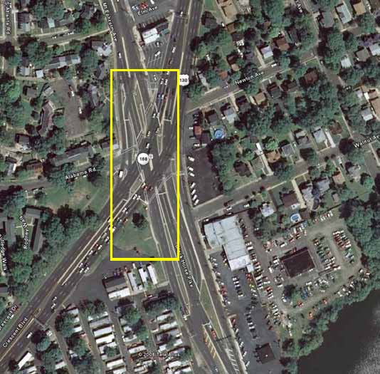
Source: Google™ Earth
Figure 152. Photo. Aerial view of parallel flow intersection in Oaklyn, NJ.
|


