U.S. Department of Transportation
Federal Highway Administration
1200 New Jersey Avenue, SE
Washington, DC 20590
202-366-4000
Federal Highway Administration Research and Technology
Coordinating, Developing, and Delivering Highway Transportation Innovations
| REPORT |
| This report is an archived publication and may contain dated technical, contact, and link information |
|
| Publication Number: FHWA-RD-95-202 Date: June 1996 |
Publication Number: FHWA-RD-95-202 Date: June 1996 |
As indicated in Figure 1, the supporting tools of an anti-icing strategy are organized into an operations toolbox, a decision-making toolbox, and a personnel toolbox. Each comprises a combination of new, conventional, and traditional technologies, and contains capabilities, information sources, or procedures that address the toolbox function.
The operations toolbox includes capabilities for applying solid chemicals, "liquid" chemicals (i.e., chemical solutions), or prewetted solid chemicals, and for plowing. The decision-making toolbox includes long- and mid-term weather forecasts, road and road weather information, nowcasting, traffic information, patrols providing information on weather and pavement conditions, and evaluations of treatment effectiveness. The personnel toolbox consists of personnel trained in anti-icing practices and use of information sources for decision making, and stand-by and call-out procedures.
In the development of an anti-icing program, each toolbox should be viewed as a critical component of a systematic operation or practice. The required elements of the toolboxes will differ from site to site, jurisdiction to jurisdiction, or agency to agency, depending primarily on levels of service, highway agency resources, and climatic conditions, and so the selection of the tools will differ in each program design. In addition, as newer technologies become available, as more effective operational techniques are identified, and as a program is accordingly developed over the course of time, the toolboxes will expand and their elements improve. However, it will always be important that the maintenance manager select and maintain effective anti-icing support tools in the subject areas of the outline: operations, decision making, and personnel. The discussion below is written as an initial guide to assist the maintenance manager in this process.
This discussion of the operations toolbox is divided into four major categories: solid chemical application capability, chemical solution application capability, prewetted solid chemical application capability, and plowing capability. Each of these is described below. Material and equipment requirements, and discussions of techniques, are included in the descriptions.
3.1.1 Solid chemical application capability
The use of dry solid chemicals as an anti-icing treatment can be effective in many circumstances, but only those where there is sufficient moisture or accumulation on the pavement. Moisture must be available for two reasons: to prevent loss of material off a dry pavement, and to trigger the solution of the salt. For initial operations, solid chemicals will be effective when a maintenance team has the operational resources to apply the chemical as soon as possible after sufficient precipitation has fallen, but before snowpack or ice bonds to the pavement. For subsequent operations, solid chemical treatments will usually be effective as there is typically adequate moisture or accumulation during later periods of storms. Nonetheless, for either initial or subsequent operations, when there is not enough moisture or accumulation on the pavement there is likely to be loss of the chemical from the pavement. This may be caused by the blowing action of traffic, especially from high speed and commercial vehicles, or by the bouncing of particles off the pavement during spreading. It is not uncommon to see dry solid chemicals rebound up to 1/2 m (2 ft) from a dry pavement after being distributed from a conventional spreader spinner, although recently-introduced zero-velocity spreaders have enabled the placement of solid chemicals on the pavement with minimum bounce.
The material and equipment requirements for solid chemical applications are similar or identical to those used conventionally or well known by most agencies. These are discussed here.
3.1.1.1 Solid materials and gradation
The solid chemical most commonly used for anti-icing treatments is salt, or sodium chloride. A mix of solid sodium chloride and solid calcium chloride has been used by some agencies, and in some instances straight calcium chloride has been used. In fact, almost any solid chemical that has been used for deicing also can be used for anti-icing depending on operating conditions. Information on solid chemicals and solubility can be found in Appendixes A and B.
The gradations of salt used for anti-icing treatments have mostly been particle size distributions designed for deicing operations, which is appropriate in the absence of prewetting. A discussion of gradation is presented in Appendix A.
3.1.1.2 Equipment
Solid material spreaders
Originally salt was spread during snow and ice control operations by shoveling it onto the road from the truck bed. Control of application rate was not possible, and the physical exertion required over long stretches of the road was demanding.
Later, salt spreaders which could be attached to a truck were developed along the line of the fertilizer distributors used in agriculture. This was the beginning of attempts to achieve a more uniform method of applying salt to the road. Rate control of the material, however, was still not satisfactory because the spreading rate was not varied as a function of truck speed. Over-spreading occurred when the truck came to a stop, and under-spreading when the truck accelerated. When the economic and environmental demands became evident, manufacturers of spreading equipment modified their equipment to distribute snow and ice control materials at controlled flow rates and at speeds higher than were used for agricultural purposes.
Nowadays dry chemicals are applied to the roadway by means of either a hopper type spreader (Figure 2) or a dump body with an under-tailgate spreader (Figure 3). These spreaders are capable of spreading free- flowing granular materials from a minimum width of 1 m (3 ft) to a maximum of 12 m (40 ft). Generally the hopper spreaders are self-contained units mounted in dump-trucks in winter, then removed and stored in other seasons so that the trucks may be used for other maintenance work. These units consist of a steel V-box body, discharge/feed conveyer, spinner disc, power drive, and other necessary components. The V-box spreaders have hopper capacities of 3.4 to 13.2 m3 (4.5 to 17.2 yd3). At the hopper’s base is a full-length feed system whose speed is controlled from the truck cab. This feed system can be either a full-length belt, chain-drag belt, or a longitudinal auger. These systems feed material into a chute where it falls onto a spinner that spreads it laterally across the road.
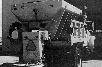
Figure 2. Hopper type spreader.
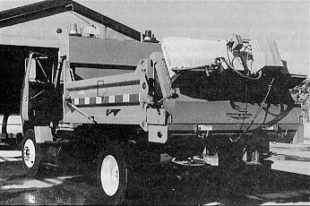
Figure 3. Under-tailgate spreader with prewetting equipment.
The under-tailgate spreader is also a self-contained unit that slips into a dump body and is easily removed and hooked up. These devices consist of a small hopper, an auger feed mechanism, hydraulic driver system, and a spinner disc. Both under-tailgate and hopper spreaders have been used successfully for anti-icing operations.
The variables affecting application rate of a given material are 1) area of the gate opening on a hopper box or the opening in the bottom of the tailgate hopper, 2) feed-belt or auger speed, and 3) truck speed. The gate opening height is an adjustment made at the time of calibration and generally is not changed during spreading operations. Thus, to control the actual spreading rate, the speed of the feed belt or auger needs to be considered along with truck speed. The methods that can be used to control the spreading rate of spreaders fall into three categories: 1) no control, 2) manual control, and 3) automatic control.
Automatic control of material application rates is achieved with ground-speed-oriented controllers. These units automatically adjust a pressure-compensation valve. A truck operator with an automatic controller is able to maintain a constant application rate of material on the road without having to adjust the valve opening to conform to the changing speed of the truck. To spread a constant amount of material along a road, a truck operator need only select an application rate. With some controllers, the spreading width can also be selected. Changes can be made at any time during operation - the automatic controller does the rest. Manual control, however, requires continual adjustment of the valve to maintain a constant application rate.
Automatic controllers use a truck-speed sensor for adjusting the opening of the pressure-compensation valve which in turn controls the operating speed of the feed mechanism. Various types of truck-speed sensors are available. Most are connected to the speedometer cable, while some measure the rotation of the drive shaft or a wheel. There is not enough information in the literature to suggest which type of sensor is the most durable, reliable, or appropriate for anti-icing operations. However, all commercially available units appear to be equally suitable.
There are two types of automatic controllers: the open-loop system and the closed-loop system. Both types require a speed sensor. The open-loop controller uses only this sensor to adjust the hydraulic valve opening. In the closed-loop system, a second sensor detects the operating speed of the feed-belt or auger. The closed-loop controller integrates the two signals to adjust the hydraulic valve opening automatically.
Many maintenance managers believe that an open-loop controller with its single truck-speed sensor provides adequate control of the application rate. They feel that annual equipment maintenance and calibration avoid the need for the second sensor provided with the closed-loop system. Some also believe that, because much material is not uniform but lumpy, very close control of the feed-belt or auger speed is not necessary.
Other users prefer the multiple control provided by closed-loop controller systems. They feel the second sensor is needed to correct changes which occur during snow and ice control operations such as wear of spreader equipment and variations in performance of the spreader’s hydraulic fluid. Wear can change the calibration of the equipment. Also, the variable operating temperature and aging of the spreader’s hydraulic fluid change the operation of the feed-belt, auger and the spinner motors.
Regardless of the type of spreader, it is extremely important to calibrate it to ensure that the desired quantity of material is really being applied. All equipment should be calibrated before winter operations begin. Though most agencies do this, they are less likely to check the manufacturer’s calibration on new equipment delivered from the factory. It is good practice to do so. Also, many agencies assume calibration is necessary only before the season begins and don’t realize that settings may change with use. Changes in mechanical linkages and components may occur, and hydraulic systems perform differently as the season progresses. It is also good practice to recalibrate the spreader equipment after any maintenance is performed on the spreader/truck system.
Anti-icing operations generally require applying a controlled quantity of chemical (often as little as 30 kg/lane-km (100 lb/lane-mi), and in some cases even less) uniformly across the road. To determine a spreader’s capability to control application rate and the distribution pattern, the equipment can be evaluated and calibrated following the "Proposed American Testing Protocol for Winter Maintenance Spreaders." This protocol is reported in SHRP H-385 report Development of Anti-Icing Technology (2). Another procedure for calibrating application rate is outlined in the Salt Institute’s The Snowfighter’s Handbook (3).
Solid chemical storage facilities
Solid chemicals should be stored under cover or inside a building. Chemicals stored in the open pick up moisture, produce leachate which drains into water sources, and develop a waste outer crust. When loaded into a spreader, the crust breaks into lumps that may clog the spreading equipment or will at least interrupt the feeding of the spinner.
Many types of barns or silos are in use for chemical storage, ranging from a simple roof over the stockpile (Figure 4) to a complete building (Figure 5). These facilities may also house the spreader(s) under the same or appended roof.
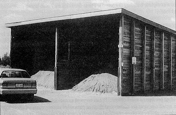
Figure 4. Simple roof over stockpile.
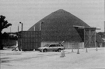
Figure 5. Enclosed structure for chemical storage.
The number of storage loading points for a given roadway system is determined by the following considerations: 1) the maximum cycle time allowed for a spreading operation; 2) the level of service of the road segments to be treated; 3) special features such as bridges, tunnels, and intersections; and 4) the route length of the spreaders. The route length determines the number of material storage locations (sheds) and the way they are distributed geographically. It is possible that the route length or range of operation of a spreader used in anti-icing operations can be expanded over that used for conventional practices. As such, the important factors in determining the number of storage locations are the first three enumerated above. It is possible that the number of storage loading points can be consolidated through the use of anti-icing operations.
3.1.2 Liquid chemical (chemical solution) application capability
Though solid or prewetted solid chemicals can be used as anti-icing treatments, there are advantages to use of liquids in small amounts for some conditions at pavement temperatures of about -5°C (23°F) and above. These include the ability to place chemical uniformly over the pavement at relatively fast spreading speeds, and the ability to place chemical onto dry pavement as a pre-storm treatment to avert delays that may lead to bonded snow or ice. However, this means putting the chemical down before enough snow has accumulated to keep the chemical from reaching the pavement or from being excessively diluted. In some situations it may be beneficial to remove snow and slush from the road using methods that are more thorough than conventional techniques. This will be discussed later in Section 3.1.4 on plowing. Liquids can be used at pavement temperatures below -5°C (23°F) by increasing the application rate over the levels recommended for -5°C (23°F) and above. The cost effectiveness of using higher liquid chemical application rates at lower pavement temperatures needs to be evaluated on a case-by-case basis.
3.1.2.1 Chemical solutions
Five chemicals have been used for liquid anti-icing treatments: sodium chloride (NaCl), magnesium chloride (MgCl2), calcium chloride (CaCl2), calcium magnesium acetate (CMA), and potassium acetate (KAc). Appendix A presents information on the properties of these chemicals and instructions for preparing various liquid concentrations. Appendix B contains information on the freezing-point of these five brines as a function of the solution concentrations.
3.1.2.2 Equipment
Liquid application equipment
There are two principal types of liquid application equipment for highway use. One uses spinners consisting of either multiple rotating disks or a single disk (Figure 6). The other type uses nozzles on a distributor bar (Figure 7). Either spreader may be chassis-mounted (fixed on the frame) (Figure 8); be a "slip-in" unit that can be placed temporarily in the bed of a dump truck or on the frame and removed during the off-season (Figure 9); or it can be a trailer, or "tow-behind" unit (Figure 10).
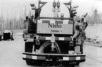
Figure 6. Single disk liquid spreader.
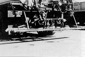
Figure 7. Liquid spreader using a distributor bar with nozzles.
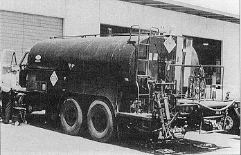
Figure 8. Chassis-mounted liquid spreader.
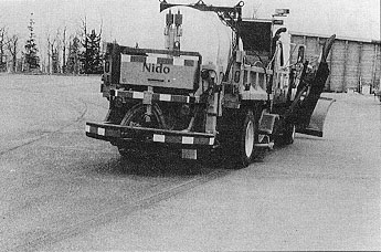
Figure 9. Slip-in liquid spreader.
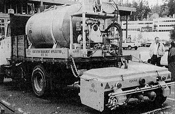
Figure 10. Tow-behind liquid spreader.
Until recently, most liquid applicators were made in Europe and Scandinavia. Several United States firms now provide highway spreader equipment and spreader components for distributing liquid chemicals (and prewetted solids).
Descriptions of the capabilities of a nozzle-type and a spinner-type spreader are presented here. They are provided only as examples for discussion purposes, and are not to be taken as endorsements or as recommended specifications.
Nozzle-type spreader. This spreader, shown in Figure 10, sprays the liquid from nozzles at a low height above the road to reduce the influence of air turbulence behind the vehicle that can cause the liquid to disperse before hitting the pavement. The unit is designed to be towed by a truck equipped with a liquid tank. The spreader is powered by its own traction-driven wheel and also has a ground-speed control.
In this particular unit, the liquid chemical flows by gravity through a clear 75 mm (3 in) plastic hose from the tank to the spreader, where two liquid pumps provide an adequate supply of liquid chemical to an array of nozzles. The two diaphragm pumps share a common inlet filter. The spraybar is 2.3 m (89 in) long and is equipped with six nozzles--three large and three small. The large nozzles spray over a 3.5 m (11.5 ft) width. At low speeds, the smaller nozzles are used. As the truck’s speed increases and the need for liquid volume increases, the smaller nozzles are shut off automatically and the larger nozzles are supplied without a break in spray pattern. As the truck slows down, the reverse process occurs.
Three additional stainless steel nozzles are mounted on the left end of the spray bar. These apply liquid to the left lane. A total width of 7 m (23 ft) can be sprayed with the spraybar and side nozzles. Each side nozzle is pressure regulated to ensure an even flow at all speeds.
Spinner-type spreader. This unit, shown in Figure 6, attaches to the rear of a truck equipped with liquid tanks. The unit can be powered either by the vehicle’s hydraulic system or by a separate road wheel.
In this unit, the liquid chemical is pumped by two impeller pumps to a specially designed stainless steel spinner. This is slightly convex with 10 curved vanes, and the spinner mechanism is manually adjustable to give asymmetric or symmetric spread patterns. The unit can apply liquid over a spread width of 2 to 8 m (7 to 26 ft) while traveling between 10 and 60 km/h (5 and 40 mph).
There is not enough information in the literature to suggest which type of liquid spreader is the most reliable or effective for anti-icing operations. The nozzle type can have problems with nozzles plugging or can dispense such a fine mist that it disperses before hitting the pavement surface. Some nozzle type designs incorporate large size (6 mm (0.25 in) or larger) spray nozzles that increase the reliability of spray equipment because they require less liquid filtration and are less likely to clog. Spinner disks can dispense liquid droplets that are too large for uniform coating of the pavement surface. A highway agency interested in using a liquid spreader for anti-icing operations needs to review the spreader manufacturer’ claims carefully.
Highway agencies interested in beginning or experimenting with an anti-icing program might consider modifying some existing spreader equipment before investing in new equipment. Asphalt distributor trucks, liquid fertilizer spreaders, and spreaders used to spray for weed control have been modified and successfully used by some highway agencies (Nevada Department of Transportation and Colorado Department of Transportation to name only two) in their initial anti-icing programs. California Department of Transportation (Caltrans) has built a customized spray bar that is capable of applying 100 L (25 gal) of solution per lane mile at speeds up to 50 km/h (30 mph). Based on just 1 year’s positive experience with the spray bar, Caltrans decided to build two additional liquid spreaders.
Regardless of the type of liquid spreader used, it is extremely important to calibrate it to ensure that the desired quantity of material is actually being applied. All equipment should be calibrated before winter operations begin. Though most agencies do this, they are less likely to check the manufacturer’s calibration on new equipment delivered from the factory. It is a good practice to perform this calibration. Also, many agencies assume calibration is necessary only before the season begins and don’t realize that settings may change with use. Changes in mechanical linkages and components may occur, and hydraulic systems perform differently as the season progresses. As a check, compare the controller application rate setting against the volume remaining in the tank several times during the winter for any deviation. It is a simple matter with most liquid applicators to use a dipstick for a check.
An application that leaves the surface merely damp will be sufficient in many conditions. Since these applications do not result in flow of liquid on the pavement, the uniformity of spread must be achieved at time of application. If a nozzle or filter is plugged, that part of the road the spray normally "sees" will remain untreated. Nozzles and filters need to be checked frequently.
Spreader speed must be evaluated for the particular conditions. Turbulence will affect spread coverage uniformity. It would be desirable to have a spreader that could perform adequately at speeds close to those of the traveling public in order to reduce the speed differential and improve the safety of the operation.
Generally, experience has shown that liquid chemicals can be successfully applied at speeds up to 40 to 55 km/h (25 to 35 mph) for spinner type spreaders and at speeds up to 65 to 80 km/h (40 to 50 mph) for spray bar type spreaders. Turbulence behind the spreader truck prevents a uniform distribution pattern at higher application speeds.
The liquid supply tanks used on spreader vehicles should be made of non-corrosive material such as polyethylene. Some States have used stainless steel tanks but this adds to the weight of the system. A number of highway agencies have installed 11 m3 (3000 gal) truck-mounted tanks for use on the spreaders. They soon discovered, due to weight limitations and density of the liquid chemicals used, only 7.5 m3 (2000 gal) of liquid could be carried on the standard size truck. Also, they experienced problems with the liquid sloshing in a tank without internal baffles. It is recommended that truck-mounted tanks larger than 5.5 m3 (1500 gal) be equipped with internal baffles.
Chemical solution production facilities; salt brine
Simple NaCl brine manufacturing plants that can operate relatively trouble-free became a necessity with the use of salt brine or prewetted salt for anti-icing treatments. Highway agencies working with private companies have designed a number of salt brine production plants. As a result, there are several companies that manufacture brine production systems.
Two types of manufacturing plants are currently in use for preparation of saturated brine: batch and continuous flow. Simple batch units for temporary or small scale production can be assembled using small tanks. Water passed through a bed of rock salt by gravity will produce a solution saturated at the water temperature. Production involves loading a tank with salt and running water through it, collecting the brine in a holding tank. From there the brine is passed through a 10 μm filter or pumped into a storage tank or directly into a spreader truck. Production rates are somewhat low with this process, about 8 L/s (600 gal/h). Several agencies have assembled their own simple plants like this. The plant used by Kansas DOT is shown in Figure 11.
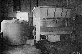
Figure 11. Kansas DOT salt brine production facility.
The concentration should be checked during production with a hydrometer (Figure 12). This device measures the specific gravity of the solution which will increase as the concentration increases. Table 1 lists hydrometer readings and the corresponding salt concentration for a solution temperature of 15°C (59°F). More efficient continuous flow units have been developed for high capacity production. These plants force water under pressure through a bed of salt. The saturated solution then flows into a storage receptacle. Salt and water are metered automatically and continuously.
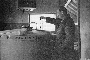
Figure 12. Testing of salt brine concentration with a hydrometer.
The following items should be considered in specifying or designing a brine manufacturing plant:
Chemical solution production facilities; liquid CMA
A CMA solution is prepared by dissolving solid CMA in water, resulting in a murky solution that settles over time to produce a clear CMA solution on top and insoluble waste on the bottom. It is recommended that the solution concentration not exceed about 25 percent. The solution tends to be stable at this concentration. If the concentration exceeds 28.5 percent, the dissolved CMA will tend to recrystallize which will clog the spray nozzles on the liquid spreaders. The recommended 25 percent concentration is prepared by mixing 1.36 kg (3.00 lb) of CMA per 3.78 L (1 gal) water. For example, 1000 kg (2205 lb) of CMA mixed with 2.78 m3 (735 gal) of water will produce 3.31 m3 (875 gal) of a 25 percent solution.
Table 1. Pure salt concentration and corresponding specific gravity (measured by a hydrometer) at 15°C (59°F).
| Percent salt |
Specific gravity at 15°C (59°F) |
Percent of saturation |
*Weight of salt kg/m3 (lb/gal) |
|---|---|---|---|
| 0 | 1.000 | 0 | 0 (0) |
| 5 | 1.035 | 20 | 51.8 (0.432) |
| 6 | 1.043 | 24 | 62.7 (0.523) |
| 7 | 1.050 | 28 | 73.5 (0.613) |
| 8 | 1.057 | 32 | 84.6 (0.706) |
| 9 | 1.065 | 36 | 95.9 (0.800) |
| 10 | 1.072 | 40 | 107.2 (0.895) |
| 11 | 1.080 | 44 | 118.9 (0.992) |
| 12 | 1.087 | 48 | 119.8 (1.000) |
| 13 | 1.095 | 52 | 131.8 (1.100) |
| 14 | 1.103 | 56 | 154.7 (1.291) |
| 15 | 1.111 | 60 | 166.8 (1.392) |
| 16 | 1.118 | 63 | 178.9 (1.493) |
| 17 | 1.126 | 67 | 191.5 (1.598) |
| 18 | 1.134 | 71 | 204.3 (1.705) |
| 19 | 1.142 | 75 | 217.2 (1.813) |
| 20 | 1.150 | 79 | 230.1 (1.920) |
| 21 | 1.158 | 83 | 243.4 (2.031) |
| 22 | 1.166 | 87 | 256.8 (2.143) |
| 23 | 1.175 | 91 | 270.3 (2.256) |
| 24 | 1.183 | 95 | 284.1 (2.371) |
| 25 | 1.191 | 99 | 293.3 (2.448) |
| 25.2 | 1.200 | 100 |
*Note: Weight of commercial salt required = (weight of pure NaCl from table) ÷ (purity in percent)
CMA will go into solution relatively quickly if vigorously agitated, and especially if warm water is used. Two methods have been used to agitate the solution in a batch system. One method uses paddle mixers in dedicated mixing tanks. For simpler installations, a flat-bottom, 7.5 m3 (2000 gal) polyethylene tank can be fitted with a small electric paddle mixer. This arrangement will provide the necessary agitation. Another method is to keep the CMA particles suspended in the water and in constant motion by the force of moving water. This is accomplished by using a high volume, high pressure pump to recirculate the water until the CMA particles are fully dissolved. This has been successfully used, but the return leg should be submerged in order to minimize the introduction of air. Too much air injection can cause foaming and premature biodegradation.
Washington DOT (WSDOT) has found that the addition of a surfactant (liquid car washing soap) to the solution is effective in suspending insoluble material for weeks. Only about 10 mL (2 teaspoons) are needed per 1000 kg (2205 lb) of solid CMA.
CMA contains about 4 percent by weight of water-insoluble material. These are impurities in the limestone used to make CMA. The particles range in size from 1 to 100 μm (40 to 4000 μin), and most will settle within 24 h after agitation is stopped. The particles are easily suspended by further agitation, and are not prone to caking.
The user needs to determine if the particles will affect performance of pumps and nozzles in the spreader equipment. If so, particles may be removed either by decanting the clear CMA liquid, or by filtering. Decanting can be avoided if a coarse mesh filter that will still prevent clogging of pumps and nozzles is used. Particles removed from the solution are not hazardous. Spreading the residue on sand piles to keep it from freezing has been recommended by some users.
The user needs to evaluate the quantity of liquid CMA needed, and what size batches are appropriate depending on storage capacity, storm frequency, and available personnel resources. This is needed in determining what mixing facilities will be required. An outside CMA mixing facility operated by WSDOT is shown in Figure 13.
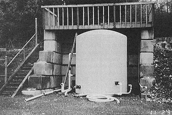
Figure 13. Outside CMA mixing facility operated by Washington DOT.
Chemical solution storage facilities
The decision whether to use inside or outside storage facilities depends on the freezing temperature of the solution and the lowest air temperature expected in the area. If the lowest air temperature is at or below the freezing-point of the solution, then inside storage should be used. However, if that is not possible, heat can be applied either with heat tapes or immersion heaters in the outside storage vessel to maintain the solution temperature above the freezing-point. Some highway agencies have buried the storage vessels and used the earth heat to maintain the temperature above freezing. Buried tanks must meet all code requirements.
The type and kind of storage vessel depends on the solution it contains and whether a secondary containment (e.g., double-walled tank or containment dike) is used. Secondary containment may be required to protect against leakage and pollution: this should be determined from the appropriate regulatory agency. If the solution is corrosive, or if the vessel will ever be used to contain a corrosive solution, the vessel should be made of a noncorrosive material such as stainless steel, glass fiber, or polyethylene.
Depending on the type of chemical solution, agitation or circulation may be required before loading material from the storage vessels to the tank on the spreader. This is especially true of solutions which have additives to reduce corrosion. Agitation can be provided either by paddles within the storage vessel or by circulation using pumps. Generally it is sufficient if this is done approximately 15 min before loading. There are some materials on the market that, if not circulated on a regular basis, will settle to the bottom of the tank. If this occurs, it is very hard to get them back into suspension.
3.1.3 Prewetted solid chemical application capability
The wetting of a solid chemical prior to spreading can improve the effectiveness of the solid chemical in many situations. As described in Appendix B, a solid chemical requires energy to go into solution, and a dry solid chemical particle will remain inert until a liquid film forms. The process of going into solution will be accelerated if a liquid is added to the solid surface. This is only one of the benefits of prewetting. Other advantages include: the solid chemical is spread more uniformly because of less waste from bouncing or traffic action (although not all waste is eliminated); granules adhere to the road surface better; there is a faster and longer-lasting effect; spreading speed can be increased; and in some cases the road surface dries more quickly. The practical result is a reduction in the resources necessary for maintaining the highway since a lower application rate translates into a spreader load covering more area, oftentimes requiring less deadheading (returning to the garage empty) to obtain material.
3.1.3.1 Materials
Solid materials and gradation
Sodium chloride (salt) has been the solid material most commonly used when applying prewetted chemicals in anti-icing operations. The material gradations, however, have ranged from coarse particle size distributions intended for deicing operations to finer sizes more appropriate for anti-icing. In deicing the aim is to get the salt particle to move rapidly through an ice or snow layer to the pavement surface. A large particle will have greater weight and therefore greater success in penetrating this layer. Since it is recommended that an anti-icing treatment be made on pavement with a minimal amount of frozen precipitation, the weight of the particles, and thus the coarse gradation, may not be an advantage. Fine particles have more surface area for an equivalent load weight and will go into solution faster. Their use will decrease the time for a solution to form and cover the entire road surface, and, if the road is clear or well plowed prior to the application, they may be more effective. However, care must be taken to plow ahead of an application when needed, to ensure that the spinner speed is adequate for spreading over the desired road width, and to ensure that the truck speed is not so high that turbulence adversely affects the uniformity of the fine particle spread.
It may be beneficial to have a gradation available at a specific site which is a compromise between those used for deicing and anti-icing in order to reduce the need for multiple stockpiles. The gradation must be selected based on individual site conditions. Several specifications for salt gradation are listed in Appendix A.
Prewetting solutions
The prewetting solutions can be made from sodium chloride (NaCl, salt brine), calcium chloride (CaCl2), magnesium chloride (MgCl2), potassium acetate (KAc), or CMA. Since CaCl2 solutions have a lower freezing-point than salt brine at the recommended concentrations, the possibility of freezing in the storage tank may make its use desirable for very cold sites. Water alone has been used as the prewetting solution, a practical approach for the load-wetting method, but only when used at higher temperatures. Since there may be a risk of freezing in the truck-mounted storage tank or in the supply line to the nozzles or at the nozzles themselves, it is generally better to use a chemical solution. Information on freezing-points of various solution concentrations is given in Appendix B.
CaCl2 has been used as a freeze-proofing additive to salt since the 1940s. Experience has shown the use of CaCl2 to have an advantage over NaCl because it is hygroscopic; i.e., it will absorb moisture from air at a relative humidity (RH) of 42 percent and higher. This serves to keep the salt crystals on the pavement after the bulk of the water has evaporated or been removed by traffic. In contrast, salt by itself will dry up and much will blow away. However, retaining the moisture may also increase tire pick-up. It has been found in field tests that a 20 percent CaCl2 solution applied to salt at the rate of 30 percent by weight of the total mixture is effective. Liquid CMA can be used as a prewetting agent and has the advantage of being essentially non-corrosive and non-polluting. Tests by Minnesota DOT have demonstrated some reduction in corrosion rate of salt when CMA is added. One practice based on several years of experience is to add 30 percent by weight saturated NaCl solution (about 25 percent) to dry salt. Although the chemical used for prewetting will be influential to an extent, it may not be as important as the prewetting/application rate.
Further discussions of solid chemicals, solubility, and chemical solutions pertinent to application of prewetted solids are presented in Appendixes A and B.
3.1.3.2 Prewetting techniques and equipment
Prewetting can be accomplished by either of three methods. First, a prewetting chemical can be injected into material stock pile at a specified dosage. Second, a liquid chemical can be sprayed onto a loaded spreader or on the material as it is being loaded into the spreader. Third, an on-board spray system mounted on the spreader and/or the dump body can add a liquid chemical to the dry chemical at the time of spreading.
Prewetting of stockpile
Wetting of stockpiled salt is performed in the late fall when the temperature of the stockpile drops to approximately 0°C (32°F). The prewetting liquid is usually calcium chloride. One method uses a 42 or 45 percent solution liquid calcium chloride, heated to over 32°C (90°F), hauled to the site by tanker truck and injected vertically into the stockpile at 0.4 to 0.6 m (1.5 to 2 ft) spacing using special spray nozzles which penetrate deep into the pile. The recommended application rate is 30 L (8 gal) of liquid calcium chloride per 1000 kg (ton) of salt. When pumped from the tank truck, the heated liquid calcium chloride flows freely through parts of the stockpile, coating the particles in contact with the liquid within the stockpile with a thin film. The degree of coating and completeness of coverage depends on the injection operator. As the solution is dispensed into the cool stockpile, its temperature rapidly drops. At about 21°C (69°F), crystallization of the solution begins. Deeper into the stockpile, crystal growth continues. As long as the temperature of the stockpile remains well below 21oC (69°F), little runoff of the solution will occur.
The stockpile wetting is performed by the vendor of the liquid calcium chloride. Therefore, the advantages of this method are 1) there is no spray equipment to purchase or maintain, 2) no installation of liquid storage tanks, 3) no training of employees on application procedures. However, there are some known disadvantages to this method of prewetting. Rain or snow on a wetted stockpile will dilute the calcium chloride and cause migration through the pile. Therefore it is essential that stockpiles be covered and placed on impervious asphalt or concrete floors. If the stockpile was built by loader equipment which traveled on top of the material, the injection process may not distribute the solution uniformly through the stockpile. The degree of coating the dry salt during the injection process is highly operator dependent. Frequent working of the pile may be required to keep the pile manageable. Finally, the material cannot be readily carried through a warm season without the solution migrating from the pile. Some highway agencies have abandoned this approach to prewetting because of these disadvantages.
Prewetting of a load or while loading
The second method of prewetting consists of spraying liquid chemical onto a loaded spreader or on the material as it is loaded into the spreader. Application on the load is accomplished by an overhead sprayer with nozzles that dispense the liquid (Figure 14). The driver pulls his truck loaded with dry chemical beneath a timer-controlled overhead spray bar system. A timer button activates a pump which sprays the loaded spreader with a solution. The recommended application rate for a 32 percent CaCl2 concentration is 45 L (12 gal) per 1000 kg (ton) of salt.
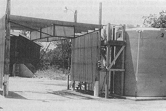
Figure 14. Overhead spraybar for prewetting chemical load in truck.
There are other variations to this second method. For example, the liquid can be sprayed onto each bucketful of salt as it is placed in the truck. Some highway agencies employ a conveyor system, spraying liquid calcium chloride on the salt as it travels up the belt to the truck.
Despite their differences, these variations on the truck-load application method have one important feature in common. First, the equipment is very modest. The basic components for all truck-load systems are a storage tank, a centrifugal pump, piping, an open spray area, a metering device, and the necessary wiring. The cost of a basic truck-load application system with all new components is between $8,000 to $10,000.
The one notable disadvantage of this second method is that it has a very high corrosive effect on the truck equipment. Another drawback is the loaded material has to be completely discharged. The unused portion cannot be left in the truck box or mingled with non-prewetted material. Finally, it is very difficult to get uniform particle coating with this method. Liquid sometimes channels through the load to the truck bed without coating segments of the dry chemical. Other times, too much liquid is used in an attempt to achieve reasonable particle coating.
Prewetting by spreader spray systems
The most common method of prewetting is through the use of on-board spreader spray systems. A spreader equipped for prewetting can apply liquids directly to the material being spread. The prewetting equipment can be an integral part of the spreader design or it can be a system that is added to an existing dry-material spreader. An existing spreader can be modified relatively simply and inexpensively. Both electric and hydraulic spray systems are used. An electric system consists of a 12 V DC electric pump rated at up to 11 L/min (3 gal/min), in-cab controls, one or two nozzles, hoses, spray tank(s) and necessary fittings. The cab controls are generally of two types. The simple type has an on/off switch and a variable speed pump control for increasing or decreasing the liquid material flow rate. Typically, this controller is not ground-speed oriented. The other type of control monitors the amount of granular material being applied and automatically adjusts the liquid flow rate to maintain a constant gallons/ton ratio. The second controller also monitors and displays overall total gallons of liquid pumped and tons of granular material spread per trip and for the entire season. These latter controllers are equipped with their own conveyor/auger sensor. They can generally be used in conjunction with any type of ground-speed control system. Both control systems operate independently of the spread width control.
The hydraulic sprayer is in-line with the conveyor/auger motor which provides a constant relationship with the amount of material being spread. The system includes a liquid spray pump, hydraulic motor, cab controls, nozzle kit, spray tank(s), and necessary hoses and fittings. Generally, a small hydraulic motor is used to drive the product pump and is coupled in series with the conveyor/auger motor. An electrical solenoid valve built into the motor housing is connected to an on/off (system) switch in the cab. An adjustable pressure regulator is located in-line between the pump and nozzles to control the liquid flow rate. An on/off, cab-mounted light displays when the solenoid is engaged. There is also a low pressure sensor to indicate when the liquid level is low or if a problem exists in the system. The system generally includes between two and four brass spray nozzles. Some nozzles have variable orifice openings which provide an extended range of liquid material output.
Generally the on-board spreader tanks are made of molded polyethylene and are provided with a replaceable output-line screen strainer and shut-off valves. Tank capacity is between 0.25 and 0.5 m3 (60 and 125 gal). Some manufacturers can provide stainless steel tanks in lieu of the polyethylene.
The prewetting equipment available from Scandinavian/European sources includes designs that automatically maintain a constant liquid-to-solid ratio regardless of variations in truck speed, spread quantity, or spread width. These prewetting systems are also equipped with hydraulic controls that automatically reduce the solid quantity exiting the conveyor belt 30 percent by weight when the liquid system is engaged. The liquid is pumped through a check valve, then flows by gravity onto the spinner. The dry material and liquid mix as they travel along the curved vanes of the spinner. Nozzles are not used to prewet the material in these designs.
As with all spreaders, periodic calibrations should be made, and any radical deviation in the spreader output compared to the control setting (e.g., running out before the route is completed, or having material remaining) should be investigated. Of some concern is spread uniformity. Although spinner spreaders leave "waves" of material on the road, traffic should distribute a solid or prewetted chemical over the road in both anti-icing and deicing applications. Although a maximum spreading speed of about 64 km/h (40 mph) is achievable, the actual speed used must be selected to ensure uniform material distribution. Also, in order to achieve as uniform a distribution as possible, ground-speed-oriented controls should be used. These modulate the material flow rate as a function of vehicle speed to obtain a constant area coverage.
The prewetting equipment in use by highway agencies is not trouble free. Frequent failures of electric pumps have been reported along with spray nozzle clogging. Also, in some designs, the add-on hydraulic system is not totally compatible with the truck’s hydraulic system. The more sophisticated foreign prewetting equipment also has experienced operational problems. Ruptures have occurred in the liquid chemical feed lines and liquid line couplings have broken or come loose during anti-icing operations.
Chemical solution production and chemical storage facilities
The chemical solution production and storage facilities needed for prewetting operations are generally the same as those needed for liquid applications. However, smaller production/storage facilities may be adequate because of the lesser volumes of the chemical solution that will be required. Storage facilities needed for the solid chemicals are the same as those required for solid chemical applications. If stockpile prewetting techniques are used, storage techniques described above should be used.
3.1.4 Plowing capability
The primary role of snowplowing in an anti-icing operation is to remove as much snow or loose ice as appropriate before applying chemicals in order that excessive dilution is avoided and the applied chemical can be effective. Because the initial chemical treatment should be placed before a significant accumulation, this is generally more important for subsequent operations. However, prior to liquid applications, it is essential that the pavement be cleared of as much snow or loose ice as possible, which may be important even for the initial operation.
If the pavement and snow are cold and dry, and it is apparent that the snow in tire tracks is not adhering to the pavement, then plowing is all that will be necessary.
3.1.4.1 Types of snowplows
There are many types of snowplows. These include one-way front plows, reversible plows, deformable moldboard plows, underbody plows, side wings, and plows specifically designed for slush removal. All plows are hydraulically controlled. In most cases, it takes only a short while to mount and dismount the plows using a quick-change buffer system.
Hydraulically extendible plows have recently been developed. The width of the plow can be extended to the left or right hand side, depending on the manufacturer. These plows are best suited to roads that vary in width. The extendible plows typically allow width adjustment between 3 and 4 m (9 and 12 ft).
Side wing plows can be attached to trucks and motor graders. The one-way front plow and underbody plow can be used simultaneously with the side wing plows.
3.1.4.2 Cutting edges
Cutting edges are available that are made of synthetic polymers, rubber, steel, and carbide inserts. Their performance is dependent on highway and snow and ice conditions. Some highway agencies have experimented to establish the effectiveness of different edges for different conditions. For example, Washington State Department of Transportation has demonstrated that polymer edges are effective for removing slush.
During anti-icing operations the cutting edge should be kept as close to the pavement as possible in an attempt to remove all the snow and slush. Thus, the use of casters or shoes on the plow is not recommended.
3.1.4.3 Slush blades
So-called slush plows have been developed in Sweden and Finland that use two blades, the leading blade having a cutting edge of steel and the trailing blade having an edge of rubber. This design is more effective over a wider range of conditions than is possible with either blade alone. The double blade plows are very good when the consistency of slush varies. Rubber blades are effective only in the removal of wet slush. The wetter the slush, the thicker the rubber blade can be. The slush blades are either spring loaded or hydraulically controlled to maintain pressure on the road surface. These blades cannot remove wet or compacted snow because of their flexibility; they will fold back and become ineffective.
The discussion of the tools in the decision-making toolbox is divided into six major categories: weather forecast information, road and road weather information, nowcasting, traffic information, patrols, and evaluations of treatment effectiveness. Each of these categories is described below.
3.2.1 Weather forecast information
The decision whether or not to initiate a treatment, when to start and what treatment to apply, can only be made if good weather information is available. This includes forecasts for each geographical region of when precipitation is expected to start, what form it will be, the probable air temperatures and the temperature trend during and after the storm, and the wind direction and speed. One source of this information on a regional and national basis is the National Weather Service. Its products must cover the entire gamut of weather users, from agricultural to marine and aviation interests. As a consequence, NWS forecasts are not generally specific enough for maintenance managers to use for decision making for an effective anti-icing program. A good source of locally-specific, timely forecasts is a contract forecast service. Guidelines for selecting a VAMS (Value Added Meteorological Service) along with a sample Request for Proposal for services are included in the report SHRP-H-351 Road Weather Information Systems, Volume 2: Implementation Guide (4).
3.2.2 Road and road weather information
3.2.2.1 Road information
Real-time knowledge of the pavement surface state is necessary for making an informed decision on treatment: the pavement temperature, whether it is wet or dry, and some indication of the concentration of a freezing-point depressant. The most important is pavement temperature. The solubility of all chemicals varies with temperature. The lower the temperature the less the solubility. An ice-control chemical must form a solution in water in order to depress the freezing-point. The pavement temperature will determine if it will form an ice-melting interface at the pavement surface. Air temperature is less important at the critical time of application and immediately following since there is usually a lag between air temperature change and the response of the pavement surface. Nonetheless, the air temperature trend is important to track because pavement temperature will usually follow the air temperature within a few hours depending on the difference in the air temperatures, the amount of solar radiation, wind, and the characteristics of the road.
Pavement sensors accomplish this monitoring and warning function. In addition to their real-time monitoring function, pavement temperature sensors can be used to generate a forecast of pavement temperature trend and warn when it will drop below freezing. This warning can occur several hours before the event, providing sufficient time to plan operations and avoid unnecessary costs.
In addition to measuring temperature most pavement sensors give a relative value of the chemical concentration on the sensor surface based on conductivity measurement. It will serve as a guide to whether some chemical remains on the road and help in making the decision whether or not to retreat. Another capability is available on some of the newest types of pavement sensors: measurement of the freezing-point of the solution on the detector. Its value lies in warning of the refreeze of a chemical treatment which has been diluted by melted snow or ice.
Remote measurement of amount and type of precipitation will guide the maintenance manager in deploying available resources most effectively. It is not unusual for part of a region to be receiving freezing rain, another part snow, and still another no precipitation.
Using the most appropriate chemical and application rate for the condition, scheduling only plowing, or choosing to do nothing can all be informed decisions based on road and weather information (see Section 4 for guidance on operational options).
3.2.2.2 Road Weather Information Systems (RWIS) and their components
Road weather information systems (RWIS) are networks of weather data-gathering and road condition monitoring systems and their associated communications, processing, and display facilities which provide decision information to maintenance managers. The most visible components of RWIS are the roadside installations of system components (Figure 15). A single site, which may have many sensors, is referred to as a remote processing unit (RPU) station. The RPU station typically consists of atmospheric sensors mounted on some form of a tower, sensors embedded in the pavement surface and beneath the surface, and an enclosure which contains data processing capability and communications equipment.
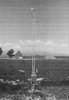
Figure 15. RWIS roadside installation.
Data from the sensors are formatted at the RPU. They are transmitted to a central processing unit (CPU) where they may be stored, retransmitted to other workstations or locations, or accessed directly. The CPU can be a separate computer or a workstation.
Another component of a RWIS is the data processing and display capability used by the maintenance personnel. The actual system configuration depends on the management structure of the maintenance organization. This component can be a computer workstation in a maintenance facility or at a District or Area headquarters. It can also be a portable computer a manager, supervisor or foreman takes home.
Whoever makes the decisions for allocating resources for snow and ice control should have access to the latest weather and road information. If decisions are made from a central office, perhaps one workstation allocated with the CPU will suffice. If decision making is decentralized, workstations and/or portable computers should be available to the local decision makers for them to access data.
Additional information about RWIS, their selection, procurement, siting, use, maintenance, and calibration can be obtained in the two-volume SHRP report Road Weather Information Systems, Volume 1: Research Report (SHRP-H-350) and Volume 2: Implementation Guide (SHRP-H-351) (5), (4).
3.2.2.3 Role of thermal mapping
Thermal mapping, or thermography, is the process of determining thermal profiles of road surfaces using infrared sensors. The measurements are typically made in the early morning hours, when there is the least change in the pavement temperature during the measurement process. They are also made under different atmospheric conditions, since the radiation balance at the surface is related to the atmospheric conditions, including cloud cover, wind speed, and precipitation.
A variation of thermal mapping is called road climatology. Additional data are acquired when measuring pavement temperature, including air temperature, relative humidity, and climatological characteristics of the pavement environment. The additional data are input to a short-range (up to 4 h) forecasting model for pavement temperature.
Thermal mapping of highway segments has been conducted in several States, including Washington, Nevada, and Minnesota. The data from thermal mapping have assisted in siting RPU stations, forecasting pavement temperatures for locations where no RWIS sensors exist, and for developing snow- and ice-control strategies. Other potential locations for thermal mapping include those areas where anti-icing operations are used, where reduced chemical areas exist, or where a significant number of different microclimates exist in a given area. Thermal mapping may also point to representative RPU locations that can eliminate the need for one or more sites.
Thermal mapping profiles can be used to infer pavement temperatures between sensor locations where the temperatures are known. An extension of this process is to forecast temperatures along the roadway based on the forecasts of temperatures at known points. This approach has been used in the United Kingdom in areas where frost or ice formation on the roads is a concern.
Better routing or allocation of maintenance resources and personnel is possible based on thermal mapping. The data can allow staging of responses to only those road segments expected to be below freezing. It can also indicate certain areas or locations that may not need attention.
Research has indicated that thermal information from the road environment can be obtained using relatively inexpensive hand-held radiometers (2, 5). Vehicle-mounted instruments for measuring pavement temperatures are already used by some State highway agencies.
There is some thought that thermal mapping should be considered when variations of pavement temperature greater than 5°C (9°F) are possible, or when the road elevation changes more than about 200 m (650 ft) over the segment length of interest. These "rules of thumb" are for general guidance and have not been validated by research data.
3.2.3 Nowcasting
Nowcasting refers to the use of real-time data for short-term forecasting. It relies on the rapid transmittal of data from RWIS installations, radar, patrols (see Section 3.2.5), and any other information source for making a judgment of the probable weather and pavement condition/temperature over the next hour or two. Nowcasting is one important tool for making the decision of when to call in personnel. Mobilization timing may vary among sites, therefore the frequency of weather information updating required for a nowcast will also vary with the site. Nowcasts can be provided by a weather service or performed by the maintenance manager. Specially trained maintenance managers in some highway agencies already perform this duty using the necessary information available from a variety of sources.
3.2.4 Traffic information
Vehicles can affect the pavement surface in several ways: tires compact snow, abrade it, displace or disperse it; heat from tire friction, engine, and the exhaust system can add measurable heat to the pavement surface. As described previously, they can also result in applied chemical being blown from the pavement. As a consequence, they can influence, both positively and negatively, the effectiveness of anti-icing treatments, and should be considered in the decision-making process. The traffic information most important for making operational decisions is the variation of traffic rate throughout a 24 h period.
3.2.5 Patrols
There is no substitute for visual observation of weather conditions and conditions of the pavement surface. Observations remain an important tool for making operational decisions even when an agency has access to and experience with new technology such as RWIS. Use of patrols for this purpose can be highly effective. Though the State or local highway patrol can fulfill this role, trained maintenance personnel are better prepared to judge the severity of conditions and to make or recommend corrective action.
3.2.6 Evaluations of treatment effectiveness
Maintenance decisions should not be based on a rigid, automatic basis but rather on the assessment of a need. In contrast to prescribing that chemicals be applied, or plow runs be made every hour or two or other fixed interval, decision on treatment need can be based on a number of information sources. The first and most obvious is the visual observations of precipitation/weather and pavement conditions from patrols, as discussed above, and from operators. The second is an indication or the measurement of chemical concentration on the pavement. The third is the measurement of frictional resistance to sliding.
The availability of chemical concentration indicators appears to enhance the timing of subsequent applications by providing indications of the dilution of the chemical. A manager can time the reapplication of chemicals so that the operation is complete before the freezing-point of the brine on the pavement surface starts to climb and, especially, before it reaches 0°C (32°F). Where decision makers have confidence in these data, they can be used as a basis for establishing cycle times of the repeat applications for different conditions.
Measurement of friction was used successfully in the SHRP and FHWA anti-icing projects. An agency may find it reasonable to establish this as a technique used during patrols. There are many devices for measuring friction. Skid trailers are commonly used for the measurement of the coefficient of friction, but for various reasons related to safety and equipment deterioration, they are not normally used on snow-covered pavements. Specialized vehicles incorporating a fifth wheel, which measures the increase in force when braked at a controlled slip rate, are available, but high cost has limited their use mainly to airports. A low-cost device was used in both the SHRP and FHWA test programs because it can be installed in most any vehicle and can produce reliable measurements. It gives a direct readout of friction coefficient when the vehicle is hard-braked from 65 km/h (40 mph). Its repeatability is acceptable for treatment analysis and decision support purposes, provided the device is calibrated and operated in accordance with the manufacturer’s specifications. Because it requires hard braking, however, it is not suitable for use in heavy traffic.
In addition to evaluations during a storm, it is beneficial for the personnel of each maintenance area to conduct a post-storm evaluation of the treatment effectiveness. This can help identify areas needing improvement and changes that can be made in the treatment strategy. A post-season review of treatment effectiveness is likewise helpful. It can help identify where changes are needed in equipment, material, and route configurations, and can begin a process of engineering an anti-icing program to fit the exact needs of a site or agency. It can also help identify where changes in personnel procedures and training are needed to improve the effectiveness of the winter maintenance program.
The discussion of the tools in the personnel toolbox is divided into two major categories: trained personnel for anti-icing decision making and operations, and deployment of personnel. Each of these is described below.
3.3.1 Trained personnel for anti-icing decision making and operations
It is essential for effective implementation of an anti-icing program that personnel be trained in the details of the workings of the program. Anti-icing techniques and operations may be so foreign to many operators and managers that old ideas must be banished before a workable program can be started. Everybody resists change, but change in most cases is what is required for an anti-icing program to be successful. An anti-icing program will necessitate more information for making an informed decision and may involve different methods and materials than do conventional methods. This will require an emphasis on training. This training can be accomplished by a consultant or highway agency staff using this manual and other material developed under FHWA and SHRP studies (1,2). Workshop material being produced under a current FHWA study (6) can be used also during the training.
3.3.2 Deployment of personnel
Deployment of personnel for anti-icing operations involves improved standby and call-out procedures. Use of modern weather forecasting information will provide more time in advance of a storm to plan operations. With better information, personnel can be advised of standby status with more certainty of need. Personnel on standby must abide by agency requirements regarding alcohol consumption, availability, and rest. Since many agencies may pay personnel for standby time, reducing unproductive call-outs and standby time will represent large savings.
Once the decision has been made that a snow and ice control operation is necessary based on accurate and timely weather information, crews must be called out. The necessary weather information needed to make the decision to initiate call-out procedures must be provided in a timely manner to ensure adequate lead time for mobilization of resources. Lead time may vary by site, thus weather information needs may also vary by site. This is especially important for anti-icing operations as the timing of the initial treatment is critical. By minimizing the mobilization time, total crew time may be reduced or crew availability may be extended. A well-organized call-out system must be in place to mobilize crews within the required time. Automated telephone calling systems can assist in streamlining the call-out process.

