U.S. Department of Transportation
Federal Highway Administration
1200 New Jersey Avenue, SE
Washington, DC 20590
202-366-4000
Federal Highway Administration Research and Technology
Coordinating, Developing, and Delivering Highway Transportation Innovations
 |
| This report is an archived publication and may contain dated technical, contact, and link information |
|
Publication Number: FHWA-RD-98-057
|
Human Factors Design Guidelines for Advanced Traveler Information Systems (ATIS)and Commercial Vehicle Operations (CVO)
CHAPTER 5: ROUTING AND NAVIGATION GUIDELINES
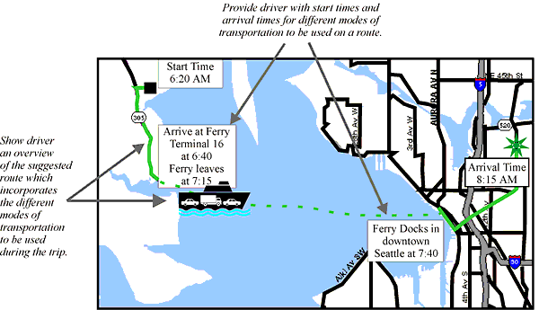
PRESENTATION OF TRAVEL COORDINATION INFORMATIONIntroduction: Travel coordination information refers to information regarding different modes of transportation (e.g., buses, trains, and subways), that may be used in conjunction with driving a vehicle. This information might include real–time updates of actual bus arrival times and anticipated travel times, and would allow coordination of multimode trips.
Schematic Example of Presenting Travel Coordination Information
Important Note: The map display depicted above is provided solely to augment this Design Guideline by illustrating general design principles. It may not be suitable for your immediate application without modification. Supporting Rationale: In Reference 1, a literature review, an analysis, and the results of applying a research–based design tool were used to identify the most appropriate display type, trip status, and display format to use when displaying travel coordination information. It was determined that due to both the amount of information being presented and the complexity of that information, the system should present travel coordination information to the driver while the vehicle is stationary. Activities performed before the trip has begun are not constrained by many of the safety considerations that apply to in–transit displays. This means that designers can place less emphasis on reducing visual and mental attention, and that they should instead focus their display considerations on standard human–computer interface issues, such as optimizing display efficiency and ease of use. Special Design Considerations: According to Reference 2, the main human constraint with this subsystem will be entering the information into the computer system. The drivers' ability to operate the system will depend upon their familiarity with computers and their ability to navigate complex menu systems. The driver may also be constrained by his or her perceptions of system reliability. If the computer supplies erroneous information, or information is presented in a confusing way, the advice might not be followed. A study reported in Reference 3 found that information which is less than 70 percent reliable will reduce the driver's trust in the system. Also, Reference 4 suggests that traffic information, such as estimated arrival times, be updated at least every 15 minutes. Cross References: Accuracy of Routing Information Key References:
*Primarily expert judgement
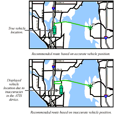
VEHICLE LOCATION ACCURACYIntroduction: Vehicle location accuracy refers to the difference between the actual position of the vehicle and the position of the vehicle as presented by an ATIS or CVO device. Accuracy is a function of both the variability inherent to the method of determining the vehicle's position (e.g., differential GPS provides a more accurate position estimate than does raw GPS) and, in the case of a moving vehicle, the latency in determining the position. Error attributable to the position sensing system is often described as the ellipse (or circle) that contains the true position of the vehicle a known percentage of time. Typically, 95 percent or 99 percent is used as the criterion for the error envelope. The root mean square (RMS) error is an alternative method commonly used to describe the position error. Position error due to latency is a function of the update rate and the velocity of the vehicle. Assuming that the system is able to determine the position of the vehicle perfectly, a 1 second delay in updating the position of a vehicle traveling 100 kph (62 mph) results in an error of 27.8 m (91 ft).
Schematic Example of Presenting Accurate and Inaccurate Vehicle Location Information
Important Note: The map display depicted above is provided solely to augment this Design Guideline by illustrating general design principles. It may not be suitable for your immediate application without modification. Supporting Rationale: As summarized in Reference 1, inaccurate vehicle position information can result in a misleading route selection. The top figure on the left–hand page shows a recommended route generated by a system that has accurately determined the position of the vehicle on the road network. The bottom figure on the left–hand page shows a route that would be generated if the position error is so large that the assumed position of the vehicle is on a road parallel to the correct road. The route shown in the bottom figure, and guidance commands based on that route, would be misleading to the driver. Inaccurate information also adversely impacts the usability of a route guidance system (Reference 1). Consider a route guidance system that has a large lag. In this case, the vehicle would be closer than desirable to the point that the system should signal that a turn is upcoming. The magnitude of the error will be a function of vehicle speed. Special Design Considerations: Anecdotal evidence suggests that there are certain situations in which even accuracy to within 91 feet may not be sufficient. For example, surface streets are frequently located near, or even directly beneath, freeways or highways above the surface streets. Thus, the ATIS may confuse roadways at different surface levels that are adjacent to one another. Under such conditions, location accuracies may need to be within 10 meters or 30 feet. This is especially critical in applications where drivers must be provided advance notice of maneuvers. For systems in which contact analog symbology is displayed, vehicle position errors in alignment between symbology and the external scene must be reduced to a level that is acceptable to system users. If vehicle position information becomes degraded, or there is uncertainty about the level of accuracy, the interface should clearly provide the driver and dispatcher a message to indicate the state of the system. In cases where position error is questionable, the driver and others relying on accurate representation of the vehicle's position (e.g., a dispatcher) should be presented with a clear message that the location of the vehicle is questionable. As soon as the problem is corrected, the system should update the route information and indicate that the system is performing at the normal level of accuracy. Designers of CVO systems should be aware that the acceptability of navigation systems is strongly influenced by perceived errors in the system. As drivers and fleet managers expressed in interviews conducted in Reference 1, the trust placed in the system is critical to the frequency of use and reliance on the system. Cross References: Accuracy of Routing Information Key References:
*Primarily expert judgement
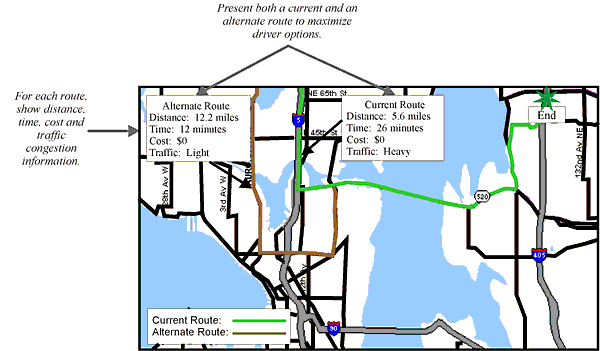
PRESENTATION OF ROUTE AND DESTINATION SELECTION INFORMATIONIntroduction: Route and destination selection information refers to destination and route selection choices that the driver engages in when the vehicle is in park and when driving to one destination. The information provided by the system might include real–time or historical congestion information, estimated travel time, and routes that optimize travel on a variety of parameters.
Schematic Example of Presenting Route and Destination Selection Information
Important Note: The map display depicted above is provided solely to augment this Design Guideline by illustrating general design principles. It may not be suitable for your immediate application without modification. Supporting Rationale: In Reference 1, a literature review, an analysis, and the results of applying a research–based design tool were used to identify the most appropriate display type, trip status, and display format to use when displaying route and destination selection information. For location, pathway, or position type information, the full or partial route video maps are clearly the most desirable. Adding text is beneficial in complex situations where the information might not be fully understood with just a picture. The redundant or supplemental use of text will help to provide context to ease in information transfer. The amount of attention required for attending to this type of information might make it necessary to display some part of the message through the auditory channel. Special Design Considerations: Reference 2 analyzed the impact of traffic information on commuters' behavior and found that pretrip information is more valuable to commuters than enroute information. Having traffic information before drivers begin their trips allows them to make the necessary decision regarding departure time and route choices. Almost 16 percent of the people surveyed indicated that they had more than one route that they used to drive to work; i.e., different on–ramps or off–ramps, different freeways or surface streets. However, a PC–based simulation study, conducted in Reference 3, discovered a "route bias" which revealed that drivers are more likely to follow advice to take the freeway than they are to take the side roads or surface streets. Thus, implementation of an ATIS system that provides route information would make even more drivers aware of potential alternate routes. Cross References: Color Coding of Traffic Flow Information Key References:
*Primarily expert judgement
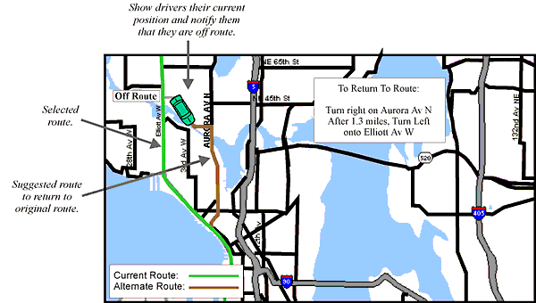
PRESENTATION OF DYNAMIC ROUTE SELECTION INFORMATIONIntroduction: Dynamic route selection information refers to any route selection function which is performed during the drive. The purpose of this ATIS function is to provide the driver with a mechanism for recovering once they have left or wandered from the intended route. When a driver makes a wrong turn and leaves the intended route, the dynamic route selection function can generate a new route which will accommodate the driver's current position.
Schematic Example of Presenting Dynamic Route Selection Information
Important Note: The map display depicted above is provided solely to augment this Design Guideline by illustrating general design principles. It may not be suitable for your immediate application without modification. Supporting Rationale: In Reference 1, a literature review, an analysis, and the results of applying a research–based design tool were used to identify the most appropriate display type, trip status, and display format to use when displaying dynamic route information. Because almost all of the information presented will be displayed while the trip is in progress, display designers must minimize the amount of additional driver attention and workload. According to Reference 2, when guiding the driver to a destination, it is more helpful for the system to present the information to the driver in the form of instructions. The sensory modality that would best convey routing instruction information would vary, depending on the level of complexity that is involved. Complex information can be presented most efficiently through the visual channel, because drivers can process detailed visual information more rapidly than they can process detailed auditory information (Reference 3). Special Design Considerations: There are a number of ways that an ATIS could deal with situations in which the driver has left a selected route, including recalculating a new route based on the current position or providing instructions on how to return to the original route. Another issue for designers to consider is whether or not the driver should have the option to reject the suggested route given by the computer. Perhaps the driver does not believe the suggested route would save them any time, or perhaps the suggested route would take the driver through a section of the city that the driver wishes to avoid for some reason. In these instances, the driver might want to be able to reject the route and select a different one. However, the amount of attention required for performing this task while driving could be substantially more than can be allocated safely. Therefore, the design effort needs to concentrate on the user interface and on making as much of the function automatic as possible. If the procedure for getting back on route is relatively simple (e.g., a single turn), then an auditory message might be used. Reference 2 states that drivers prefer systems that keep them informed of their current position. Therefore, throughout this guideline document, the current position of the vehicle is displayed to the driver using a small car icon. Cross References: Color Coding of Traffic Flow Information Key References:
*Primarily expert judgement
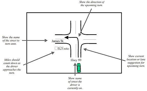
PRESENTATION OF ROUTE GUIDANCE INFORMATIONIntroduction: Given a destination and current location, route guidance information refers to navigation directions in a turn–by–turn format. Route guidance provides information such as: distance to the next turn, the name of the street to turn onto, what lane to be in to make the turn, and the direction of the upcoming turn.
Schematic Example of Presenting Route Guidance Information
Important Note: The map display depicted above is provided solely to augment this Design Guideline by illustrating general design principles. It may not be suitable for your immediate application without modification. Supporting Rationale: In Reference 1, a literature review, an analysis, and the results of applying a research–based design tool were used to identify the most appropriate display type, trip status, and display format to use when displaying route guidance information. It was determined that almost all of the information presented during this ATIS function would be displayed while the trip was in progress and that the information should be presented in the form of turn–by–turn instructions to help avoid driver confusion or navigational errors. The sensory modality that would best convey navigation or routing instruction information will vary with the level of complexity that is involved. Complex information can be presented most efficiently through the visual channel, because drivers can process detailed visual information more rapidly than they can process detailed auditory information (Reference 2). However, simple information presented through the auditory channel may be easier for drivers to attend to. Special Design Considerations: Several authors (see References 3, 4, and 5) have stressed the importance of limiting the amount of information presented to the drivers when they are driving. Reference 6 argues that the display should be limited to only the necessary information, including: the next turn, how far away the turn is, what street to turn on, and which direction to turn on a prespecified route. It also suggests that people who are familiar with an area prefer to be given cross streets of the next turn, whereas people who are unfamiliar with an area prefer to be given distance information. Distance values could be displayed continuously or intermittently (e.g., every 0.1 or 0.2 miles). An example of an effectively used continuous display would be one that lists the distance to the next turn at the top of the display screen and increments the distance downward until the turn is reached. A driver requesting an update to total distance remaining for the route would be served best by an intermittent display. Whether information is going to be displayed continuously or intermittently should influence a designer's choice of sensory modality, since continuous information can decrease the salience of time–critical information and increase required search and retrieval time. Additionally, continuous auditory information is likely to annoy the driver (Reference 7 and 8). An important factor in intermittent displays is that the driver needs to be alerted to the presence of new information, or the information might be missed. Also, research conducted in Reference 9 suggests that views of intersections should be plan views (directly overhead) or aerial views (as from a flying plane), but not perspective views (from the driver's eye view). This is in accordance with a laboratory study which found that 87 percent of drivers tested preferred the plan view (Reference 10). Cross References: Timing of Auditory Navigation Information Key References:
*Primarily expert judgement
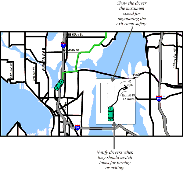
PRESENTATION OF LANE POSITION INFORMATIONIntroduction: Lane position information refers to information presented for the purpose of helping drivers avoid last minute lane changes. Providing the driver with a little extra lead time to make a lane change might be beneficial when driving an unfamiliar route or in circumstances where traffic is heavy and lane maneuvers may be difficult.
Schematic Example of Presenting Lane Position Information
Important Note: The map display depicted above is provided solely to augment this Design Guideline by illustrating general design principles. It may not be suitable for your immediate application without modification. Supporting Rationale: In Reference 1, a literature review, an analysis, and the results of applying a research–based design tool were used to identify the most appropriate display type, trip status, and display format to use when displaying lane position information. It was determined that this type of information would be most useful to the driver if displayed while in transit and that the convenience benefits would outweigh the costs (in terms of required driver resources to process this information). Reference 2 confirmed the ability of drivers to look at messages on an ATIS without affecting their lane–keeping abilities. Special Design Considerations: In Reference 3, it is argued that the display should show two turns in a row when the turns are in close proximity (in succession). This would allow drivers to execute the first maneuver in such a way as to be prepared for the second maneuver. While there has not been empirical work done to determine what constitutes "close proximity," a reasonable working definition was determined to be 0.1 miles (0.06 kilometers), since that is the accuracy of all displayed information. When multiple messages are being presented, they should be presented in the order in which the driver must respond to them. For example, the message that should be attended to and responded to first should be presented first. Presenting lane position information would be very beneficial for commercial drivers. Many commercial vehicles require substantially more time than private vehicles to make any kind of maneuver or lane change. Thus, it may be important to take vehicle size into consideration when determining the timing necessary for presenting lane position information. Cross References: Complexity of ATIS Information Timing of Auditory Navigation Information Key References:
*Primarily expert judgement
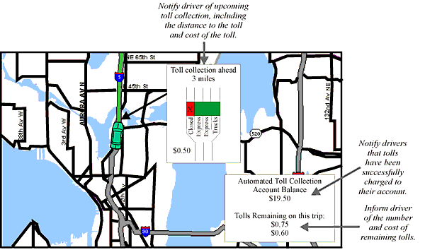
PRESENTATION OF TOLL COLLECTION INFORMATIONIntroduction: Automated toll collection refers to allowing a vehicle to travel through a toll roadway without stopping to pay tolls. Instead, tolls would be automatically deducted from the driver's account as they drive past toll collection areas. This would enable tolls to be adjusted to balance traffic flows (higher toll rate during peak rush hour). Also, automated toll collection would provide drivers information regarding toll credits and the current toll costs.
Schematic Example of Presenting Toll Collection Information
Important Note: The map display depicted above is provided solely to augment this Design Guideline by illustrating general design principles. It may not be suitable for your immediate application without modification. Supporting Rationale: In Reference 1, a literature review, an analysis, and the results of applying a research–based design tool were used to identify the most appropriate display type, trip status, and display format to use when displaying automated toll collection information. It was determined that this type of information would be most useful to the driver if displayed while in transit and that the convenience benefits would outweigh the costs (in terms of required driver resources). Also, because presentation of this type of information would be relatively infrequent and not extremely important with regard to aiding in navigation or driver safety, the visual modality was chosen as the primary method for presenting this type of information. Special Design Considerations: The driver currently learns of the cost of the toll by reading a sign posted before the toll. ATIS can supply the driver with this information, as well as the vehicle's toll credit. The primary factor influencing the success of this function lies in driver acceptance of the technology. Thus, driver attitudes will govern the success of this system. If drivers believe that the system assesses tolls incorrectly or invades their privacy, they may prefer manual toll collection. By providing drivers with estimated costs of a trip, automated toll collection facilitates trip planning and predrive route and destination selection. Rapid communication of congestion pricing toll changes would facilitate multimode travel coordination and planning by aiding drivers in the comparison of private vehicle versus mass transit options. Cross References: Complexity of ATIS Information Key References:
*Primarily expert judgement
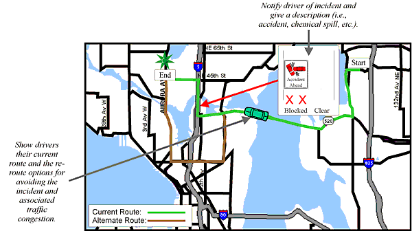
PRESENTATION OF ROUTE INCIDENT INFORMATIONIntroduction: Route incident information refers to the data necessary for helping a driver travel to a selected destination when incidents are detected along the route.
Schematic Example of Presenting Route Navigation Information
Important Note: The map display depicted above is provided solely to augment this Design Guideline by illustrating general design principles. It may not be suitable for your immediate application without modification. Supporting Rationale: In Reference 1, a literature review, an analysis, and the results of applying a research–based design tool were used to identify the most appropriate display type, trip status, and display format for route incident information. Due to the nature of route incident information, it was determined that this type of information would be most useful to the driver if displayed while in transit and that the convenience benefits would outweigh the costs, in terms of required driver resources. It was also recommended that the auditory modality be used to: (1) provide an auditory prompt to look at the visual display for changing or upcoming information (thus lessening the need for the driver to constantly scan the visual display in preparation for an upcoming event), or (2) have some type of simple visual information presentation to supplement the auditory message (so that a message that is not fully understood or remembered can be checked, or later referred to, via the visual display). These uses of the auditory modality can reduce the visual attention demand of navigation systems, without the problems caused by sole reliance on voice messaging (Reference 2). Special Design Considerations: It has been suggested that merely telling drivers the effect on traffic associated with an incident is insufficient (Reference 3). Instead, drivers should be told the cause of the congestion (e.g., accident, construction, etc.). Also, the driver might be given information about which lanes are open (e.g., green arrows for open and red Xs for blocked). Lane numbers are not desired. If the term "lane blocked" is used, the assumption is that the blockage is temporary, often due to an accident. The term "lane blocked" is preferred over "lane condition." "Closed" implies a long–term problem. If re–route options are simple (e.g., one turn), then the instructions may be safely presented to the driver while the vehicle is in motion. Cross References: Color Coding of Traffic Flow Information Key References:
*Primarily expert judgement
FHWA-RD-98-057
|
||||||||||||||||||||||||||||||||||||||||||||||||||||||||||||||||||||||||||||||||||||||||||||||||||||||||||||||||||||||||||||||||||||||||||||||||||||||||||||||||||||||||||||||