U.S. Department of Transportation
Federal Highway Administration
1200 New Jersey Avenue, SE
Washington, DC 20590
202-366-4000
Federal Highway Administration Research and Technology
Coordinating, Developing, and Delivering Highway Transportation Innovations
 |
| This report is an archived publication and may contain dated technical, contact, and link information |
|
Publication Number: FHWA-HRT-05-103
Date: July 2006 |
Federal Highway Administration University Course on Bicycle and Pedestrian TransportationPDF Version (668 KB) PDF files can be viewed with the Acrobat® Reader®
LESSON 10: PEDESTRIAN FACILITY SIGNING AND PAVEMENT MARKINGS
10.1 IntroductionTraffic engineers use a wide variety of road signs and pavement markings. Some are used to alert motorists to pedestrian activity and to direct pedestrians to defined crossings. Problems are created, however, when pedestrians assume that signs and paint will protect them from cars. Drivers, on the other hand, often ignore pedestrian signs and markings because they seldom see many pedestrians. As a result, signs and paint may lull pedestrians into a false sense of security. This lesson provides an overall philosophy for the use of signs and pavement markings, as well as details on how these traffic control measures should be employed. Crosswalk markings at intersections are covered in more detail in lesson 11. The major sections of this lesson are as follows:
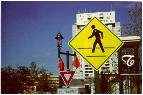
10.2 BackgroundSigning is governed by the FHWA’s MUTCD, which provides specifications on the design and placement of traffic control signs installed within public rights–of–way.(1) The MUTCD encourages a conservative use of signs (sections 2A–1, 2A–6, 2B–1, and 2C–1). Signs should only be installed when they fulfill a need based on an engineering study or engineering judgment (see figure 10–1). The prevailing thinking among traffic engineers is that overuse of traffic control signs leads to disrespect of signs.
Used judiciously and located with consistency, signs and markings can be effective. Jurisdictions should develop clear guidelines for use and should avoid excessive reliance on signs and paint to control motorist behavior. This may mean altering and/or relocating existing signs and markings. It may be best to eliminate markings and signs that have proven to be ineffective or harmful to pedestrian safety. There is ongoing debate and studies are in progress to determine whether markings (especially written messages) improve pedestrian safety, whether crosswalks are useful at midblock locations, and whether signs contribute to visual overload for motorists and breed disrespect for messages.
10.3 Planning and Design ConsiderationsMUTCD outlines guidelines governing signs and pavement markings. At the same time, it does not prohibit creative regulatory design. MUTCD does not define criteria for crosswalk location or striping options. "Crosswalks should be marked at all intersections where there is substantial conflict between vehicular and pedestrian movements." Much is left to engineering judgment to determine what is "substantial." As a result, there is leeway in adapting guidelines to specific signing and marking policy needs. Colors for signs and markings must conform to the color schedule recommended by MUTCD to promote uniformity and understanding from jurisdiction to jurisdiction. For the background color of signs, use:
For pavement markings, use:
10.4 Regulatory SignsThese signs are used to inform motorists or pedestrians of a legal requirement and should only be used when the legal requirement is not otherwise apparent. They are generally rectangular in shape, usually consisting of a black legend on a white background, and shall be reflectorized or illuminated. Many motorist signs, including stop signs, yield signs, turn restrictions, and speed limits, have a direct or indirect impact on pedestrians. The NO TURN ON RED (R10–11a) sign may be used in some instances to facilitate pedestrian movements. MUTCD lists six conditions when no turn on red may be considered, three of which are directly related to pedestrians or signal timing for pedestrians. Considerable controversy has arisen regarding pedestrian safety implications and right–turn–on–red operations, ranging from a study by Zador, which indicated a significant increase in pedestrian crashes where right–turn–on–red movements are allowed, to studies by AASHTO and McGee, which concluded that right–turn–on–red movements do not create a pedestrian safety problem.(3,4,5) The use of NO TURN ON RED signs at an intersection should be evaluated on a case–by–case basis. Less restrictive alternatives should be considered in lieu of NO TURN ON RED. Also, supplementary signs, such as WHEN PEDESTRIANS ARE PRESENT or WHEN CHILDREN ARE PRESENT may be placed below the NO TURN ON RED sign. There are occasions when no–turn–on–red restrictions are beneficial, and specific recommendations relating to pedestrians include:
There are a number of regulatory signs directed at pedestrians, which include:
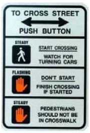
Other signs may be used for pedestrians at traffic signals to define the meaning of the WALK, DON’T WALK, and flashing DON’T WALK signal indications (see figure 10–4). In MUTCD, the signs R10–3a, b, c, and d help define crossing signal indications. The top section shows a walking person symbol, labeled STEADY, or the word WALK to the left of the words START CROSSING. The next section shows an orange caution symbol of an upraised hand with the palm facing the viewer, labeled FLASHING, or the words DON’T WALK to the left of the text "DON’T START FINISH CROSSING IF STARTED" on three lines. The third section shows an orange caution symbol of an upraised hand with the palm facing the viewer, labeled STEADY, to the left of the words DON’T CROSS or PEDESTRIANS SHOULD NOT BE IN CROSSWALK. These signs are generally located near the pushbuttons used to activate the crosswalk signal.
The decision to use these signs (or alternatively, stickers mounted directly on the signal pole) is strictly an engineering judgment and is primarily for educational purposes. As such, their use may be more helpful near schools and areas with concentrations of elderly pedestrians—two high–risk areas. This information may also be effectively converted into brochures for distribution and ongoing educational purposes.
10.5 Warning SignsWarning signs are used to inform unfamiliar motorists/pedestrians of unusual or unexpected conditions. Warning signs predominantly fall under the permissive category ("may" condition), and when used, should be placed to provide adequate response times. Warning signs are generally diamond–shaped with black letters or drawings on a yellow background and shall be reflectorized or illuminated. Overuse of warning signs breeds disrespect and should be avoided. The warning sign predominantly used to warn motorists of possible pedestrian conflicts is the Pedestrian Crossing sign (W11–2) (see figure 10–5). This sign should be installed in advance of midblock crosswalks or other locations where pedestrians may not be expected to cross. This significantly minimizes their use at most urban intersections since pedestrian crossings are an expected occurrence. This sign may also be selectively used in advance of high–volume pedestrian crossing locations to add emphasis to the crosswalk. The advance pedestrian crossing sign provides more advance warning to motorists than crosswalk markings, and on some occasions, may be used when crosswalk markings do not exist. Where there are multiple crossing locations that cannot be concentrated to a single location, a supplemental distance plate may be used (NEXT XX FEET). The advance pedestrian crossing signs should not be mounted with another warning sign (except for a supplemental distance sign or an advisory speed plate) or regulatory sign (except for NO PARKING signs) to avoid information overload and to allow for an improved driver response. When placing signs, care should be taken in relation to other signs to avoid sign clutter and to allow adequate motorist response. The MUTCD specifies a 76– by 76–cm (30– by 30–in) sign size. However, it may be helpful to use a larger [91– by 91–cm (36– by 36–in)] sign on higher speed or wider arterial streets.
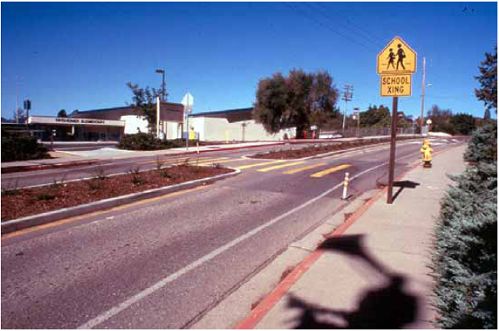
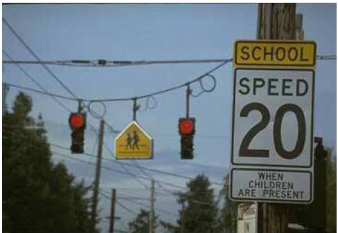
Figure 10–5. Photo. This pedestrian crossing sign is fluorescent yellow green (FYG), allowing it to be more visible. At the actual location of the pedestrian crossing, the pedestrian crossing sign (W11–2) is used but supplemented with a black–on–yellow diagonally downward pointing arrow plaque (W16–7p). This combination of pedestrian crossing sign and supplemental arrow plaque is intended to indicate the pedestrian crossing location. The Playground sign (W15–1) may be used in advance of a designated children’s play area to warn motorists of a potentially high concentration of young children. This sign should generally not be needed on local or residential streets where children are expected. Furthermore, play areas should not be located adjacent to high–speed major or arterial streets, or if so, should be fenced off to prevent children from darting into the street. According to the ITE publication, Traffic Control Devices Handbook, CAUTION—CHILDREN AT PLAY or SLOW CHILDREN signs should not be used since they may encourage children to play in the street and may encourage parents to be less vigilant.(6) Such signs also provide no guidance to motorists as to a safe speed, and the sign has no legal basis for determining what a motorist should do. Furthermore, motorists should expect children to be at play in all residential areas, and the lack of signing on some streets may indicate otherwise. The signs are unenforceable and act as another roadside obstacle to pedestrians and errant motorists. Use of these nonstandard signs may also imply that the involved jurisdiction approves of streets as playgrounds, which may result in the jurisdiction being vulnerable to tort liability. School Warning signs include the advance school crossing signs (S1–1), the school crossing sign (S2–1), SCHOOL BUS STOP AHEAD (S3–1) sign, and others. School–related traffic control devices are discussed in detail in part VII ("Traffic Controls for School Areas") of MUTCD.(1) A reduced speed limit sign with flashing lights can be installed ahead of the actual crossing (see figure 10–6). The lights are set to flash during school hours, alerting drivers that a lower speed limit is in effect when the flashers are operating. Another sign and light combination is SCHOOL SPEED LIMIT XX, where the speed limit is illuminated during school hours.
Figure 10–6. Photo. Flashing lights, school crossing signs, and a low speed limit gives motorists plenty of warning of the crossing area ahead. MUTCD allows for the development of other specialty warning signs based on engineering judgment for unique conditions. These signs can be designed to alert unfamiliar motorists or pedestrians of unexpected conditions and should follow the general criteria for the design of warning signs. Their use should be minimized to retain effectiveness and should be based on engineering judgment.
10.6 Directional SignsDirectional signs for pedestrians are intended to assist people who are new to the area or to assist residents who may not know the most direct route to a destination by foot. Use distances meaningful to pedestrians, such as the number of blocks or average walking time.
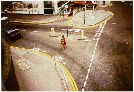
10.7 Pavement Word and Symbol MarkingsMUTCD allows for the use of pavement word and symbol markings such as SCHOOL XING or PED XING, as motorist warning devices (MUTCD, Section 3B–20). These may be helpful on high–volume or high–speed streets with unusual geometrics (such as vertical or horizontal curves) in advance of a pedestrian crossing area. Markings should be white and placed to provide an adequate motorist response. Their use should be kept to a minimum to retain effectiveness. Consideration should be given to snow conditions that may obliterate the markings during portions of the year in some regions of the country and also to the agency’s ability to maintain these pavement markings. If used, the word or symbol markings should generally be used in each approach lane (except for the SCHOOL message). Some agencies have also attempted to communicate with pedestrians by using pavement word markings such as LOOK BOTH WAYS or other symbols to encourage pedestrians to look for vehicles and to enter the road cautiously (see figure 10–7).
Figure 10–7. Photo. "Look Right" or "Look Left" is painted on the street next to the curb in the United Kingdom. All pavement word and symbol markings require periodic maintenance and replacement after resurfacing. If such markings are used, it is advisable to maintain an inventory of stencils for periodic checking and refurbishment.
10.8 Crosswalk MarkingsHere is an excerpt from MUTCD regarding the use of crosswalk markings:(1)
Table 10–1 presents some minimum and maximum design requirements for crosswalk pavement markings. Below are some additional MUTCD guidelines for crosswalk installation:
Table 10–1. Design requirements for crosswalk pavement markings.
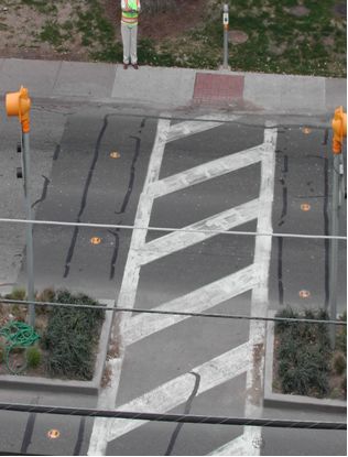
Three styles of crosswalk markings are shown at a roadway intersection in figure 10–8: two parallel solid white lines (transverse lines) at the top of the figure, solid white diagonal lines between two parallel solid white lines on the left side, and a series of closely spaced solid white lines (longitudinal lines) placed at the intersection parallel to the direction of travel on the bottom side of the figure. Figure 10–9 shows examples of these and other marking patterns typically used and the common names they go by.
Marked Versus Unmarked CrosswalksIn the United States, there has been considerable controversy concerning marked crosswalks and whether they increase or decrease pedestrian safety at uncontrolled crossing locations (i.e., intersections or midblock locations with no traffic signals or stop signs on the main road approach). Some believe that marked crosswalks enhance the visibility, safety, and mobility of pedestrians, while others think that they generate overly confident feelings of safety which may cause pedestrians to be more vulnerable to collisions with motor vehicles. Zegeer, et al., performed a study to determine which types of uncontrolled locations merited a marked crosswalk and which ones would require more treatment in order to provide a safe crossing for pedestrians.(7) The study revealed that "under no condition was the presence of a marked crosswalk alone at an uncontrolled location associated with a significantly lower pedestrian crash rate compared to an unmarked crosswalk," and at some locations, especially those with volumes greater than 12,000 vehicles per day, having a marked crosswalk was associated with a higher pedestrian crash experience compared to an unmarked crossing. Table 10–2 below provides a summary of the study’s recommendations for where marked crosswalks should be provided at uncontrolled locations. Table 10–2. Recommendations for installing marked crosswalks and other needed pedestrian improvements at uncontrolled locations.*
10.9 ITS TechnologyThe information and images in the following ITS section have been taken directly from the PedSmart website maintained by PBIC with funding from the USDOT and the Centers for Disease Control and Prevention.(8) In–Roadway Warning LightsIn–roadway warning lights are being used at crosswalks to alert motorists to the presence of a pedestrian crossing or preparing to cross the street (see figures 10–10 and 10–11). Since the lights only flash when activated by the pedestrian, the motorist receives real–time information indicating that a pedestrian is in the vicinity of the crosswalk. The amber lights are embedded in the pavement on both sides of the crosswalk and oriented to face oncoming traffic. When the pedestrian activates the system, either by using a pushbutton or through detection from an automated device, the lights begin to flash at a constant rate, warning the motorist that a pedestrian is in the vicinity of the crosswalk ahead.
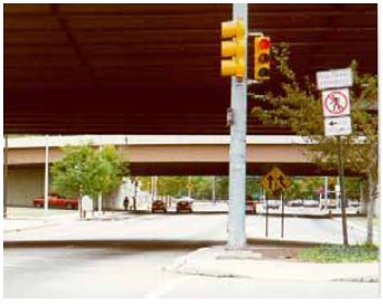
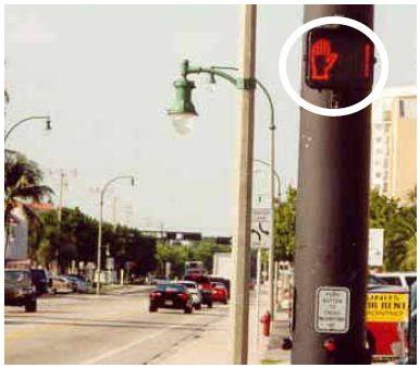
Figure 10–11. Photo. Working example of in–roadway warning lights with pedestrian pushbutton in Austin, Texas. The amber light–emitting diode (LED) lights flash in unison at a rate designed for maximum motorist recognition and are visible during the daylight as well as at night. The flashing lights are only activated when a pedestrian wants to cross and are automatically shut off after a set period of time, i.e., the time required for a pedestrian to safely cross the street. If installed in conjunction with the means to detect the presence of pedestrians while in the crosswalk, the crossing interval can be extended, in which case the lights would continue to flash and allow slower pedestrians to safely cross. A study by Huang, et al., in 1999 found that the "flashing crosswalk had small positive effects on reducing vehicle speeds, increasing vehicle yielding to pedestrians, and reducing pedestrian–motor vehicle conflicts," but it was less effective in channelizing pedestrians.(9) Countdown SignalCountdown signals are used in conjunction with conventional pedestrian signals to provide information to the pedestrian regarding the amount of time remaining to safely cross the street (see figure 10–12). It is hypothesized that pedestrians will use this information to make better decisions about when to enter the crosswalk. Depending on user preference, the countdown timer starts either when the WALK or Walking Person indication appears or when the flashing DON’T WALK or Hand indication appears. The timer continues counting down through the flashing DON’T WALK (Hand) clearance interval. When the steady DON’T WALK or Hand appears, the countdown signal will be at zero.
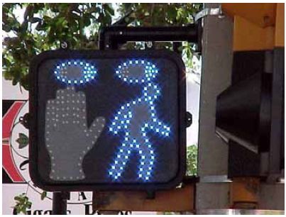
Figure 10–12. Photo. Example of countdown pedestrian signal in Lauderdale–By–The–Sea, FL. Animated Eyes DisplayAnimated eyes are intended for use at pedestrian crosswalks as an alternative to conventional pedestrian signals (see figure 10–13). Animated eyes displays are expected to encourage pedestrians to look for turning vehicles traveling on an intersecting path by including a prompt as part of the pedestrian signal. The prompt is a pair of animated eyes that scan from side to side at the start of the WALK indication. Depending on user preference, the animated eyes can be illuminated separately from the standard pedestrian symbol (walking person) for the beginning of the WALK phase or illuminated concurrently with the standard symbol.
The animated eyes display uses an LED pedestrian signal head and adds animated eyes that scan from side to side. The device uses narrow (8–degree) field of view blue (460 nanometers (nm)) LEDs on a black background. The display is highly visible to pedestrians while restricting signal visibility to motorists. The eyes, which appear to scan left and right at the rate of one cycle per second, are 13 cm (5 in) wide, 6.9 cm (2.7 in) high, and 5.7 cm (2.25 in) apart. The WALK portion of the display is a 28.4–cm–high (11.2–in–high) outline of a walking person (a standard pedestrian symbol) constructed from blue LEDs. The DON’T WALK display is a 28.4–cm–high (11.2–in–high) upraised hand constructed from Portland orange (6.15 nm) LEDs. Detection DevicesMicrowave Detector The microwave pedestrian detector provides the means to automatically detect the presence of pedestrians in the targeted curbside area and/or while moving in a designated crosswalk area. In figure 10–14, pedestrians in the curbside microwave detection zone (shown in red) will activate the call feature, while slower pedestrians detected within the onstreet detection zones (shown in blue) receive more time to cross the street.
When used at the curbside area, it may either replace or augment the standard pushbutton used to activate the pedestrian call feature. When used to detect pedestrians in the crosswalk, its function is to detect the presence of individuals requiring additional time to cross, appropriately extend the clearance interval, and provide more time to cross. Infrared Detector The passive infrared detector provides the capability to automatically detect the presence of pedestrians in the targeted curbside area or within the crosswalk. In figure 10–15, pedestrians entering the curbside infrared detection zone (shown in red) will activate the pedestrian call feature, while those detected in the crosswalk (shown in blue) will extend the clearance interval. When used to detect pedestrians in the crosswalk, its function is to detect the presence of individuals requiring additional time to cross, appropriately extend the clearance interval, and provide more time to cross. Both these types of detectors function by sensing changes in thermal radiation caused by pedestrian movement within the targeted areas. These detectors may be used either to supplement or to replace the standard pushbutton used to activate the pedestrian call feature.
Illuminated PushbuttonsThe illuminated pushbutton is simple technology designed to provide immediate feedback to the pedestrian that the button is working and that the signal will change (see figure 10–16). Use of the illuminated button may reduce the number of pedestrians who cross against the signal because they have no indication that a standard pushbutton is working. Because of an immediate response from the light, the illuminated button may also result in fewer pedestrians pushing the button multiple times. This can result in longer life for the pushbutton itself. 
10.10 Student ExerciseThe need to develop and detail pedestrian signs and pavement markings in a manner in which these provisions can be constructed within the normal field of highway construction is an extremely important issue. Signs and pavement markings for a proposed roadway project are specified through a detailed system of standard drawings, specifications, and bid item numbers. An example plan view drawing demonstrating this method for highway–related signs and pavement markings using California Department of Transportation (Caltrans) specifications is provided for reference in figure 10–17.
Engineers use such standards to ensure uniform construction; contractors use them to develop construction cost estimates for their bids. The use of these procedures in developing designs is a critical link in the continuum of planning, designing, and constructing transportation facilities. Construction of pedestrian and bicycle facilities should make full use of this well–established system. Most State DOTs have a variety of specifications that pertain to pedestrian and bicycle facilities. Using the summary of standard drawings for bicycle and pedestrian facility construction provided below (taken from the Caltrans Standard Plans document), develop a plan to install pedestrian signs and pavement markings that uses nomenclature and reference standards from your State DOT. Estimate the quantity of each construction item needed and develop an engineer’s construction cost estimate. You will need to utilize the following resources:
10.11 References and Additional ResourcesThe references for this lesson are:
Additional resources for this lesson include:
FHWA-HRT-05-103 |
|||||||||||||||||||||||||||||||||||||||||||||||||||||||||||||||||||||||||||||||||||||||||||||||||||||||||||||||||||||||||||