U.S. Department of Transportation
Federal Highway Administration
1200 New Jersey Avenue, SE
Washington, DC 20590
202-366-4000
Federal Highway Administration Research and Technology
Coordinating, Developing, and Delivering Highway Transportation Innovations
 |
| This report is an archived publication and may contain dated technical, contact, and link information |
|
Publication Number: FHWA-HRT-05-111
Date: July 2006 |
Federal Highway Administration University Course on Bicycle and Pedestrian TransportationPDF Version (371 KB) PDF files can be viewed with the Acrobat® Reader®
LESSON 14: SHARED ROADWAYS
14.1 IntroductionAs indicated in lesson 13, there are a variety of ways to accommodate bicyclists on roadways. In many cases, a few simple construction projects can make a big difference for bicyclists, such as replacing unsafe drain grates, filling potholes, or maintaining roadway shoulders so that they are free of debris. This lesson provides information on shared roadways, which can encompass the following:
The major sections of this lesson are as follows:
This lesson has been primarily derived from the Oregon Bicycle and Pedestrian Plan, a statewide policy, planning, and design manual for the Oregon Department of Transportation (ODOT) in 1995.(1) Additional information has been gathered from the 1999 AASHTO Guide for the Development of Bicycle Facilities, which is abbreviated in this lesson as the AASHTO Guide.(2)
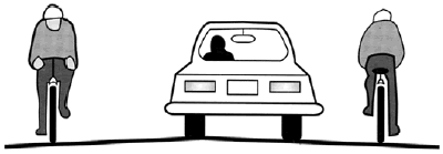
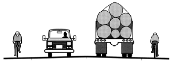
14.2 Shared RoadwaysSince bicyclists are legally able to use nearly all roadways, the great majority of road mileage can be technically classified as shared roadways (see figure 14–1). The exception for shared roadways are where bicycling has been expressly prohibited by an ordinance or law, such as on some city streets or controlled–access freeways in some States. The 1999 AASHTO Guide defines a shared roadway as "a roadway which is open to both bicycle and motor vehicle travel. This may be an existing roadway, street with wide curb lanes, or a road with paved shoulders."(2)
In the United States, most shared roadways have no provisions for bicycle travel and are perceived by many bicyclists to be unsafe or at least uninviting. However, there are some design measures that can be taken to ensure that shared roadways accommodate bicyclists safely and efficiently. This lesson describes several design options for shared roadways, including wide curb lanes, shoulder bikeways, and bicycle boulevards. There is also a discussion of practices to be avoided, such as sidewalk bikeways. There are no specific bicycle standards for most shared roadways; they are simply the roads that currently exist as local urban or rural roads and highways. Mile for mile, shared roadways are the most common bikeway type. Shared roadways are suitable in urban areas on streets with low speeds—40 km/h (25 mi/h) or less—or low traffic volumes (3,000 vehicles per day or less, depending on speed and land use). In rural areas, the suitability of a shared roadway decreases as traffic speeds and volumes increase, especially on roads with poor sight distances. Where bicycle use or demand is potentially high, roads should be widened to include paved shoulders or shoulder bikeways if the travel speeds and volumes on the roadway are high. Many urban local streets carry excessive traffic volumes at speeds higher than they were designed to carry. These can function as shared roadways if traffic speeds and volumes are reduced. There are many traffic calming techniques that can make these streets more amenable to bicycling on the road.
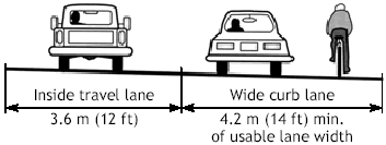
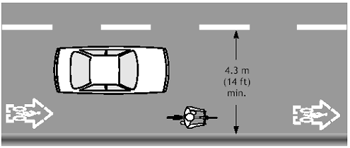
14.3 Wide Curb LanesA wide curb lane may be provided where there is inadequate width to provide bike lanes or shoulder bikeways. This may occur on retrofit projects where there are severe physical constraints and all other options have been pursued, such as removing parking or narrowing travel lanes. Wide curb lanes can often be installed by narrowing inner lanes on a multilane arterial, thereby reallocating roadway space so that the outside (curb) lanes are wider (see lesson 15 for roadway retrofit solutions). Wide curb lanes are not particularly attractive to most bicyclists, as they do not specifically designate road space for bicyclists. Wide curb lanes simply allow motor vehicles to pass bicyclists within a travel lane. In general, 4.2 m (14 ft) of usable lane width is the recommended width for shared–use in a wide curb lane (see figures 14–2 and 14–3). Usable width is normally measured from the edge stripe to the centerline or adjacent lane stripe, and the gutter pan should not be included as usable width. A wider curb lane (up to 4.5 m (15 ft)) may be appropriate on steep grades where bicyclists need more maneuvering space. The increased width may also be appropriate in areas where drainage grates, raised reflectors, or other pavement features detract from usable width. With these exceptions in mind, wide curb lanes greater than 4.2 m (14 ft) that extend continuously may encourage two motor vehicles to share a lane, and are therefore not recommended. In situations where more than 4.5 m (15 ft) of pavement width exist, a bike lane or paved shoulder should be considered.
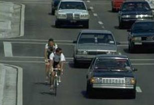
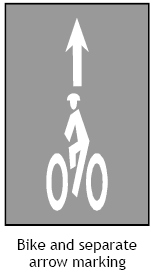
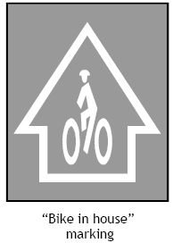
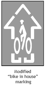
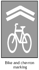
A few cities in Canada and the United States (most notably Denver) have experimented with placing a bicycle symbol with an arrow along the right side of wide curb lanes at regular intervals (see figures 14–4 and 14–5). Called a hybrid bicycle lane, this bicycle facility has not been endorsed by the AASHTO Guide or other bicycle facility design manuals. The use of this bicycle pavement marking is suggested to offer the advantages of bicycle lanes along with many of the problems associated with bicycle lanes. Proponents of this treatment indicate that the bicycle symbol clearly indicates the right side of the wide curb lane for bicyclists, while also alerting motorists to the potential presence of bicyclists on the road. There are currently no standards or guidance on how to deal with bus routes on shared roadway facilities having wide curb lanes. Extra space is needed for a bus to overtake a bicycle, so a wider curb lane (up to 4.5 m (15 ft)) may be appropriate. If both bus and bicycle traffic is significant, other alternatives besides a shared roadway should probably be considered. In some cities, a shared bus and bike lane accommodates both groups and ranges from 4.2 to 4.9 m (14 to 16 ft). Other cities have chosen to separate these two road users by providing separate bicycle and bus lanes.
Figure 14–4. Illustrations. Various pavement markings for shared roadways and wide curb lanes..
Figure 14–5. Illustration. Typical application of shared roadway pavement markings.
14.4 Roadway Shoulders or Shoulder BikewaysPaved shoulders are provided on rural highways for a variety of safety, operational, and maintenance reasons:
Width StandardsIn general, the shoulder widths recommended for rural highways in AASHTO’s Policy on Geometric Design of Highways and Streets serve bicyclists well, since wider shoulders are required on heavily traveled and high–speed roads and on those carrying large numbers of trucks.(3) When providing paved shoulders for bicycle use, a minimum width of 1.2 m (4 ft) is recommended (see figure 14–6); however, even 0.6 m (2 ft) of shoulder width will benefit more experienced bicyclists. A shoulder width of 1.5 m (5 ft) is recommended from the face of guardrail, curb, or other roadside barriers.
Certain situations may require a wider paved shoulder. On steep grades, it is desirable to maintain a 1.8–m (6–ft) shoulder (minimum of 1.5 m (5 ft)), as cyclists need more space for maneuvering. A 1.8–m (6–ft) shoulder allows a cyclist to ride far enough from the edge of the pavement to avoid debris, yet far enough from passing vehicles to avoid conflict. If there are physical width limitations, a minimum width of 1.2 m (4 ft) from the longitudinal joint between a monolithic curb and gutter and the edge of travel lane may be adequate. Where high bicycle usage is expected, it is desirable to increase the shoulder width. Additional shoulder width may also be appropriate where vehicle speeds are greater than 80 km/h (50 mi/h), or where there is significant truck, bus, or recreational vehicle traffic. Pavement DesignMany existing gravel shoulders have sufficient width and base to support shoulder bikeways. Minor excavation and the addition of 75 to 100 millimeters (mm) (3 to 4 in) of asphalt pavement is often enough to provide shoulder bikeways. It is best to widen shoulders in conjunction with pavement overlays for several reasons:
When shoulders are provided as part of new road construction, the pavement structural design should be the same as that of the roadway. On shoulder widening projects, there may be some opportunities to reduce costs by building to a lesser thickness. A total of 50–100 mm (2–4 in) of asphalt and 50–75 mm (2–3 in) of aggregate over existing roadway shoulders may be adequate if the following conditions are met:
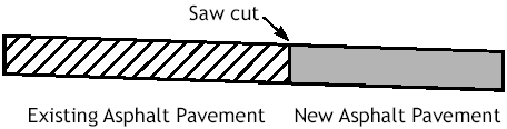
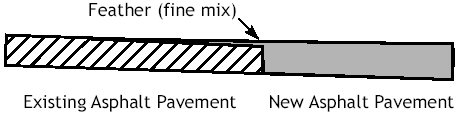
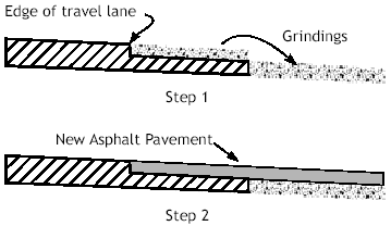
The thickness of pavement and base material will depend upon local conditions, and engineering judgment should be used. If there are short sections where the travel lanes must be reconstructed or widened, these areas should be constructed to normal full–depth standards. The Joint between the Shoulders and the Existing RoadwayThe following techniques should be used to add paved shoulders to roadways where no overlay project is scheduled:
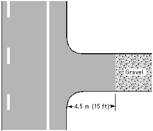
Gravel Driveways and ApproachesWherever a highway is constructed, widened, or overlaid, all gravel driveways and approaches should be paved back 4.5 m (15 ft) to prevent loose gravel from spilling onto the shoulders (see figure 14–10).
14.5 Designated Bicycle RoutesBicycle routes are specially designated shared roadways that are preferred for bicycle travel for certain recreation or transportation purposes. The 1999 AASHTO Guide also refers to a designated bicycle route as a signed shared roadway and lists the following reasons for designating signed bike routes:
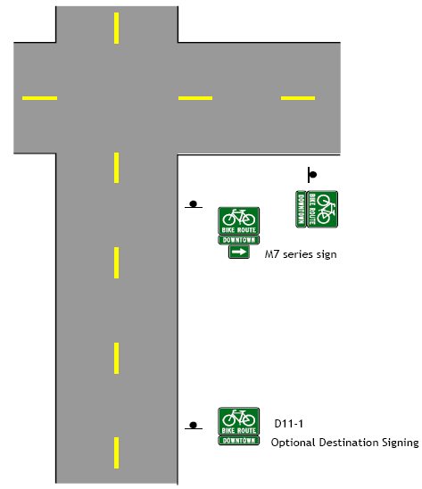
Bike route signs may also be used on streets with bike lanes, as well as on shared–use paths. Regardless of the type of facility or roadway on which they are used, it is recommended that bike route signs always include destination, direction, and distance information (see figure 14–11).
The signing of shared roadways indicates to bicyclists that there are particular advantages to using these routes compared to alternate routes. This means the responsible agencies have taken action to ensure that these routes are suitable as shared routes and will be maintained as such. The following criteria should be considered prior to signing a route:
14.6 Bicycle BoulevardsThe bicycle boulevard is a refinement of the shared roadway concept in that the operation of a local street is modified to function as a through–street exclusively for bicycles while maintaining local access for automobiles. Traffic calming devices reduce traffic speeds and extensive through traffic. Traffic controls limit conflicts between motorists and bicyclists and give priority to through–bicycle movement. Advantages of Bicycle Boulevards
Disadvantages of Bicycle Boulevards
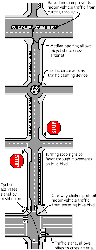
Successful bicycle boulevard implementation requires careful planning with residents and businesses to avoid unacceptable impacts. Elements of a Bicycle BoulevardSeveral elements are typically considered in the design of a bicycle boulevard (see figure 14–12):
14.7 Other Design ConsiderationsRumble StripsRumble strips are provided to alert motorists that they are wandering off the travel lanes onto the shoulder or across the centerline on an undivided highway. They are most common on rural freeways, but are also being considered on other primary and secondary highways. One of a bicyclist’s main concerns about rumble strips is the ability to control the bicycle when traveling across or along the rumble strip for such maneuvers as a left turn or to avoid debris or an obstacle on the paved shoulder. Travel to the right of the rumble strip is generally most beneficial for the bicyclist as long as that area is free of debris and obstacles and the travel path is wide enough to comfortably accommodate the bicycle. According to the 1999 AASHTO Guide, rumble strips or raised pavement markers, where installed to warn motorists they are driving on the shoulder (or discourage them from doing so), are not recommended where shoulders are used by bicyclists unless there are:(2)
If existing conditions preclude achieving the minimum desirable clearance, the width of the rumble strip may be decreased or other appropriate alternative solutions should be considered. Additional guidance on rumble strips is provided by the FHWA:(4)
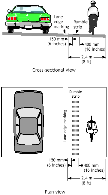
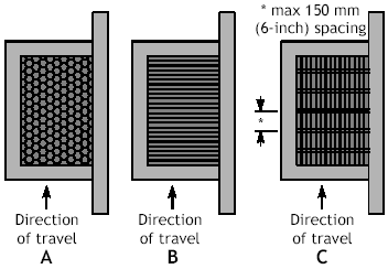
Some highway agencies have instituted policies that prohibit the use of shoulder rumble strips on roads designated as bike routes or where there is insufficient paved shoulder room remaining to accommodate bicycle travel. Others evaluate the use of rumble strips on a case–by–case basis and often opt to install them only at locations with a history of run–off–road crashes. Other designs being used or investigated employ a skip pattern of rumble strip that provides a smoother travel path throughout portions of the strip and thus allows bicyclists to move to the left when needed. Furthermore, some highway agencies are providing an aid to cyclists and all travelers in general by posting roadside signs, such as RUMBLE STRIPS AHEAD, alerting the traveler to the presence of the shoulder rumble strip. ODOT uses a rumble strip design that meets the AASHTO guidelines (see figure 14–13): 400–mm (16–in) grooves are cut into the shoulder 150 mm (6 in) from the lane edge line. On a 2.4–m (8–ft) shoulder, this leaves 1.8 m (6 ft) of usable shoulder for bicyclists.
The following recommendations come from a Colorado DOT study.(5) The standard type of ground–in rumble strips are 0.3 m (12 in) wide, with a groove depth of 9.5 mm ±3 mm (0.375 in ± 0.125 in) ground in an interrupted pattern, and is the recommended configuration for asphalt rumble strips based on the data collected for this report. No recommendation is made concerning rolled–in concrete rumble strips. In a study for the Pennsylvania DOT, the authors recommended two different "bicycle tolerable" rumble strip patterns:(6)
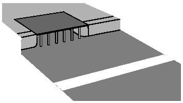
Drainage GratesCare must be taken to ensure that drainage grates are bicycle–safe. If not, a bicycle wheel may fall into a slot in the grate, causing the bicyclist to fall. Replacing existing grates with bicycle–safe grates (see A and B in figure 14–14, preferred methods) or welding thin metal straps across the grate perpendicular to the direction of travel (see C in figure 14–14, alternate method) is required. These should be checked periodically to ensure that the straps remain in place.
Note that grates with bars perpendicular to the roadway must not be placed at curb cuts, as wheelchairs could get caught in the slots. The most effective way to avoid drainage grate problems is to eliminate them entirely with the use of inlets in the curb face (see figure 14–15).
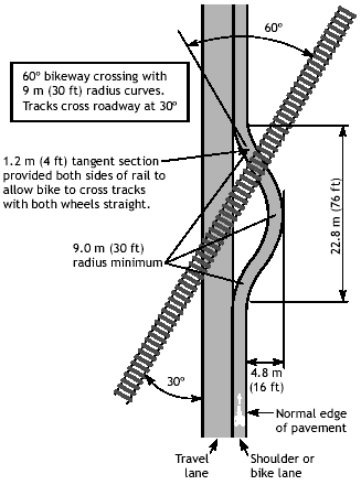
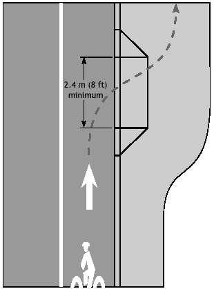
If a street–surface grate is required for drainage, care must be taken to ensure that the grate is flush with the road surface. Inlets should be raised after a pavement overlay to within 6 mm (0.25 in) of the new surface. If this is not possible or practical, the pavement must taper into drainage inlets so they do not cause an abrupt edge at the inlet. Railroad CrossingsSpecial care must be taken wherever a bikeway intersects railroad tracks. The most important improvements for bicyclists are smoothness, angle of crossing, and flange openings (see figure 14–16). Smoothness. Concrete performs better than other materials under wet conditions and, when laid with precision, provides a smooth ride. Rubberized crossings provide a durable, smooth crossing, although they tend to become slippery when wet. If asphalt pavement is used, it must be maintained in order to prevent a ridge buildup next to the rails. Timber crossings wear down rapidly and are slippery when wet. Angle of Crossing. The risk is kept to a minimum where the bikeway crosses the tracks at a 90° angle. If the skew angle is less than 45°, special attention should be given to the bikeway alignment to improve the angle of the approach, preferably to 60° or greater, so cyclists can avoid catching their wheels in the flange and losing their balance. Flange Openings. The open flange area between the rail and the roadway surface can cause problems for bicyclists, since it can catch a bicycle wheel, causing the rider to fall. Flange width must be kept to a minimum. Note that the combination of smoothness, angle, and flange opening creates conditions that affect bicyclists. By improving smoothness and flange opening, the angle becomes less critical. Sidewalk Ramps on BridgesSidewalk ramps can help bicyclists if the bridge sidewalks are wide enough for bicycle use (minimum 1.2 m (4 ft), see figure 14–17). They should be provided where motor vehicle traffic volumes and speeds are high and the shoulders on the bridge are narrow. Figure 14–16. Illustration. Bike lane or shoulder crossing railroad tracks.
Figure 14–17. Illustration. Curb ramp provides access to sidewalk.
14.8 Practices to AvoidODOT has more than 20 years of experience designing bikeways, and it has also learned from local city and county experiences. Several practices have proven to be poor ones, including sidewalk bikeways, extruded curbs, and raised pavement markings. These practices are discussed in this section. Sidewalk BikewaysSome early bikeways used sidewalks for both pedestrians and bicyclists. While in rare instances this type of facility may be necessary, or desirable for use by small children, in most cases it should be avoided. Sidewalks are not suited for bicycling for several reasons:
Bicyclists are safer when they are allowed to function as roadway vehicle operators rather than as pedestrians. Where constraints do not allow full–width walkways and bikeways, solutions should be sought to accommodate both modes (e.g., narrowing travel lanes or reducing on–street parking). In some urban situations, preference may be given to accommodating pedestrians. Sidewalks should not be signed for bicycle use—the choice should be left to the users. Extruded CurbsRaised concrete curbs create an undesirable condition when used to separate the motor vehicle lane from a bike lane or paved shoulder: Either one may hit the curb and lose control, with the motor vehicle crossing onto the bikeway or the bicyclist falling onto the roadway. At night, the curbs cast shadows on the lane, reducing the bicyclist’s visibility of the surface. Extruded curbs make bikeways difficult to maintain and tend to collect debris. They are often hit by motor vehicles, causing them to break up and scatter loose pieces onto the roadway surface. Reflectors and Raised Pavement MarkersThe placement of some raised pavement markers or reflectors can deflect a bicycle wheel, causing the bicyclist to lose control. If pavement markers are needed for motorists, they should be installed on the motorist’s side of the lane stripe, and they should have a beveled front edge.
14.9 Student ExerciseChoose a local street that would be a good candidate for a bicycle boulevard. The street segment should be several blocks in length, and should include at least one crossing of a major arterial. Prepare a conceptual design plan for the street segment, showing the location of signing, traffic signals, on–street parking, and traffic calming features. Your design should be shown in plan view, and should be accompanied by a narrative explaining the purpose of special design features.
14.10 References and Additional ResourcesThe references for this lesson are:
Additional resources for this lesson include:
FHWA-HRT-05-111 |