Capacity Analysis of Pedestrian and Bicycle Facilities
Recommended Procedures for the "Signalized Intersections" Chapter of the Highway Capacity Manual
4.2 Details of Recommended Procedure for Determining fLpb and fRpb
The following paragraphs contain the detailed procedure for computing the pedestrian-bicycle adjustment factor for right turns, fRpb , or left turns, fLpb. As an additional aid, Figures 9 and 10 provide supplemental worksheets containing this information in tabular
form.
1) Calculate pedestrian conflict zone occupancy, OCCpedg.
First, get the pedestrian flow rate, Vpedg from the conflicting pedestrian hourly volume, Vped:
Vpedg = Vped * (C/gp) (Vpedg < 5000)
Then, compute the average pedestrian occupancy during the effective pedestiran green time. Refer to Table 4 for the average occupancy, OCCpedg, or use one of the following equations:
- For pedestrian flow rates up to 1000 pedestrians/h green:
-
OCCpedg = Vpedg / 2000 (Vpedg < 1000; OCCpedg < 0.5)
- For pedestrian flow rates between 1000 and 5000 pedestrians/h green:
-
OCCpedg = 0.4 + Vpedg / 10,000 (1000 < Vpedg < 5000; 0.5 < OCCpedg < 0.9)
2) Determine the relevant conflict zone occupancy from the driver's perspective, OCCr.
- For a right turn with no bicycle interference or a left turn from a one-way street:
-
The relevant occupancy is exactly the pedestrian occupancy computed above, and: OCCr = OCCpedg
- For a right turn with bicycle interference:
-
First convert bicycle hourly volume, Vbike, to bicycles/h green, Vbikeg: Vbikeg = Vbike * (C/g) (Vbikeg < 1900)
Next, determine the relevant, combined occupancy of the adjacent pedestrian and bicycle conflict
zones. Table 5 provides this relevant occupancy, OCC r,
directlry from Vbikeg . Alternatively, determine the occupancy of the bicycle conflict zone by itself, OCCbikeg:
OCCbikeg = 0.02 + Vbikeg / 2700 (Vbikeg < 1900; OCCbikeg
< 0.72) and then compute the relevant, combined occupancy, OCCr,
by: OCCr = OCCpedg + OCCbikeg – (OCCpedg * OCCbikeg)
- For a left turn from a two-way street:
-
First check if opposing traffic screens the conflict zone for the entire effective green time:
If gq > gp Then fLpb = 1.0 ; end procedure.
If the opposing queue does not consume the entire pedestrian green, determine the pedestrian occupancy after the opposing queue clears,
OCCpedu. Use Table 6, or: OCCpedu = OCCpedg * (1 - 0.5 (gq /gp) )
The relevant conflict zone occupancy after the queue clears is the occupancy that is not screened by additional opposing vehicles.
To determine this relevant occupancy, OCCr, multiply the total occupancy after the queue clears, OCCpedu,
by the probability that opposing vehicles do not screen the conflict zone. Use Table 7 or: OCCr = OCCpedu * e-(5/3600)Vo
3) Calculate the permitted phase pedestrian-bicycle adjustment for turning vehicles, ApbT.
- If the number of receiving lanes equals the number of turning lanes (i.e., Nrec < = Nturn):
-
Vehicles cannot maneuver around pedestrians or bicycles, and the adjustment is logically
the proportion of time the conflict zone is unoccupied from the turning driver's perspective. Use Table 8, or: ApbT = 1 - OCCr
- If the number of receiving lanes exceeds the number of turning lanes (i.e., Nrec > Nturn):
-
Vehicles may have opportunities to maneuver around pedestrians or bicycles, and the effect of pedesestrians
and bicycles on turning traffic is reduced. Use Table 8, or: ApbT = 1 – 0.6 * OCCr
4) Compute the pedestrian-bicycle adjustment factor for right turns, fRpb, or left turns, fLpb.
- For right turns, the pedestrian-bicycle adjustment factor, fRpb, is:
-
fRpb = 1.0 – PRT ( 1 – ApbT)(1- PRTA)
See Table 9 for simplified equations for each of six cases for fRpb.
- For left turns, the pedestrian adjustment factor, fLpb, is:
-
fLpb = 1.0 - PLT(1 - ApbT) (1 - PLTA)
See Table 10 for simplified equations for each of six cases for fLpb.
 |
Figure 9: Supplemental worksheet for pedestrian-bicycle effects on permissive right turns |
 |
Figure 10: Supplemental worksheet for pedestrian effects on permissive left turns |
TABLE 4 Intermediate Pedestrian-Bicycle Parameters: Pedestrian Conflict Zone Occupancy (OCC pedg)
| Vpedga |
OCCpedgb |
Vpedg |
OCCpedg |
Vpedg |
OCCpedg |
Vpedg |
OCCpedg |
| 0 |
0.00 |
500 |
0.25 |
1000 |
0.50 |
3500 |
0.75 |
| 100 |
0.05 |
600 |
0.30 |
1500 |
0.55 |
4000 |
0.80 |
| 200 |
0.10 |
700 |
0.35 |
2000 |
0.60 |
4500 |
0.85 |
| 300 |
0.15 |
800 |
0.40 |
2500 |
0.65 |
≥ 5000 |
0.90 |
| 400 |
0.20 |
900 |
0.45 |
3000 |
0.70 |
|
|
a pedestrian volume/h of pedestrian green time
b average conflict zone occupancy by pedestrians during pedestrian effective green time
|
TABLE 5 Intermediate Pedestrian-Bicycle Parameters: Relevant Conflict Zone Occupancy (OCCr) For Right Turns or Unopposed Left Turns
| Bicycle Volume/h of green, Vbikeg |
| OCCpedga |
0 |
100 |
200 |
300 |
400 |
500 |
750 |
1000 |
1250 |
1500 |
1750 |
>1900 |
| 0.00 |
0.00 |
0.06 |
0.09 |
0.13 |
0.17 |
0.21 |
0.30 |
0.39 |
0.48 |
0.58 |
0.67 |
0.72 |
| 0.05 |
0.05 |
0.10 |
0.14 |
0.17 |
0.21 |
0.24 |
0.33 |
0.42 |
0.51 |
0.60 |
0.68 |
0.74 |
| 0.10 |
0.10 |
0.15 |
0.18 |
0.22 |
0.25 |
0.28 |
0.37 |
0.45 |
0.53 |
0.51 |
0.70 |
0.75 |
| 0.15 |
0.15 |
0.20 |
0.23 |
0.26 |
0.29 |
0.32 |
0.40 |
0.48 |
0.56 |
0.64 |
0.72 |
0.77 |
| 0.20 |
0.20 |
0.25 |
0.28 |
0.30 |
0.33 |
0.36 |
0.44 |
0.51 |
0.59 |
0.66 |
0.73 |
0.78 |
| 0.25 |
0.25 |
0.29 |
0.32 |
0.35 |
0.38 |
0.40 |
0.47 |
0.54 |
0.61 |
0.68 |
0.75 |
0.79 |
| 0.30 |
0.30 |
0.34 |
0.37 |
0.39 |
0.42 |
0.44 |
0.51 |
0.57 |
0.64 |
0.70 |
0.77 |
0.81 |
| 0.35 |
0.35 |
0.39 |
0.41 |
0.44 |
0.46 |
0.48 |
0.54 |
0.60 |
0.66 |
0.72 |
0.78 |
0.82 |
| 0.40 |
0.40 |
0.43 |
0.46 |
0.48 |
0.50 |
0.52 |
0.58 |
0.63 |
0.69 |
0.75 |
0.80 |
0.83 |
| 0.45 |
0.45 |
0.48 |
0.50 |
0.52 |
0.54 |
0.56 |
0.61 |
0.66 |
0.72 |
0.77 |
0.82 |
0.85 |
| 0.50 |
0.50 |
0.53 |
0.55 |
0.57 |
0.58 |
0.60 |
0.65 |
0.70 |
0.74 |
0.79 |
0.83 |
0.86 |
| 0.55 |
0.55 |
0.58 |
0.59 |
0.61 |
0.63 |
0.64 |
0.68 |
0.73 |
0.77 |
0.81 |
0.85 |
0.88 |
| 0.60 |
0.60 |
0.62 |
0.64 |
0.65 |
0.67 |
0.68 |
0.72 |
0.76 |
0.79 |
0.83 |
0.87 |
0.89 |
| 0.65 |
0.65 |
0.67 |
0.68 |
0.70 |
0.71 |
0.72 |
0.75 |
0.79 |
0.82 |
0.85 |
0.88 |
0.90 |
| 0.70 |
0.70 |
0.72 |
0.73 |
0.74 |
0.75 |
0.76 |
0.79 |
0.82 |
0.84 |
0.87 |
0.90 |
0.92 |
| 0.75 |
0.75 |
0.76 |
0.77 |
0.78 |
0.79 |
0.80 |
0.82 |
0.85 |
0.87 |
0.89 |
0.92 |
0.93 |
| 0.80 |
0.80 |
0.81 |
0.82 |
0.83 |
0.83 |
0.84 |
0.86 |
0.88 |
0.90 |
0.92 |
0.93 |
0.94 |
| 0.85 |
0.85 |
0.86 |
0.86 |
0.87 |
0.88 |
0.88 |
0.89 |
0.91 |
0.92 |
0.94 |
0.95 |
0.96 |
| 0.90 |
0.90 |
0.91 |
0.91 |
0.91 |
0.92 |
0.92 |
0.93 |
0.94 |
0.95 |
0.96 |
0.97 |
0.97 |
|
aaverge conflict zone occupancy by pedestrians during pedestrian effective green time
TABLE 6 Intermediate Pedestrian-Bicycle Parameters: Conflict Zone Occupancy After Opposing Queue Clears (OCCpedu) for Opposed Left Turns
| Ratio of Opposing Queue Time to Effect. Ped. Green, gq/gp |
|
OCC pedga |
0.0 |
0.1 |
0.2 |
0.3 |
0.4 |
0.5 |
0.6 |
0.7 |
0.8 |
0.9 |
<1.0b |
| 0.00 |
0.00 |
0.00 |
0.00 |
0.00 |
0.00 |
0.00 |
0.00 |
0.00 |
0.00 |
0.00 |
0.00 |
| 0.05 |
0.05 |
0.05 |
0.05 |
0.04 |
0.04 |
0.04 |
0.04 |
0.03 |
0.03 |
0.03 |
0.03 |
| 0.10 |
0.10 |
0.10 |
0.09 |
0.09 |
0.08 |
0.08 |
0.07 |
0.07 |
0.06 |
0.06 |
0.05 |
| 0.15 |
0.15 |
0.14 |
0.14 |
0.13 |
0.12 |
0.11 |
0.11 |
0.10 |
0.09 |
0.08 |
0.08 |
| 0.20 |
0.20 |
0.19 |
0.18 |
0.17 |
0.16 |
0.15 |
0.14 |
0.13 |
0.12 |
0.11 |
0.10 |
| 0.25 |
0.25 |
0.24 |
0.23 |
0.21 |
0.20 |
0.19 |
0.18 |
0.16 |
0.15 |
0.14 |
0.13 |
| 0.30 |
0.30 |
0.29 |
0.27 |
0.26 |
0.24 |
0.23 |
0.21 |
0.20 |
0.18 |
0.17 |
0.15 |
| 0.35 |
0.35 |
0.33 |
0.32 |
0.30 |
0.28 |
0.26 |
0.25 |
0.23 |
0.21 |
0.19 |
0.18 |
| 0.40 |
0.40 |
0.38 |
0.36 |
0.34 |
0.32 |
0.30 |
0.28 |
0.26 |
0.24 |
0.22 |
0.20 |
| 0.45 |
0.45 |
0.43 |
0.41 |
0.38 |
0.36 |
0.34 |
0.32 |
0.29 |
0.27 |
0.25 |
0.23 |
| 0.50 |
0.50 |
0.48 |
0.45 |
0.43 |
0.40 |
0.38 |
0.35 |
0.33 |
0.30 |
0.28 |
0.25 |
| 0.55 |
0.55 |
0.52 |
0.50 |
0.47 |
0.44 |
0.41 |
0.39 |
0.36 |
0.33 |
0.30 |
0.28 |
| 0.60 |
0.60 |
0.57 |
0.54 |
0.51 |
0.48 |
0.45 |
0.42 |
0.39 |
0.36 |
0.33 |
0.30 |
| 0.65 |
0.65 |
0.62 |
0.59 |
0.55 |
0.52 |
0.49 |
0.46 |
0.42 |
0.39 |
0.36 |
0.33 |
| 0.70 |
0.70 |
0.67 |
0.63 |
0.60 |
0.56 |
0.53 |
0.49 |
0.46 |
0.42 |
0.39 |
0.35 |
| 0.75 |
0.75 |
0.71 |
0.68 |
0.64 |
0.60 |
0.56 |
0.53 |
0.49 |
0.45 |
0.41 |
0.38 |
| 0.80 |
0.80 |
0.76 |
0.72 |
0.68 |
0.64 |
0.60 |
0.56 |
0.52 |
0.48 |
0.44 |
0.40 |
| 0.85 |
0.85 |
0.81 |
0.77 |
0.72 |
0.68 |
0.64 |
0.60 |
0.55 |
0.51 |
0.47 |
0.43 |
| 0.90 |
0.90 |
0.86 |
0.81 |
0.77 |
0.72 |
0.68 |
0.63 |
0.59 |
0.54 |
0.50 |
0.45 |
a average conflict zone occupancy by pedestrians during effective ped. green
b if g q /g p≥
1.0 then OCC pedu= 0.00 and f Lpb= 1.0
|
TABLE 7 Intermediate Pedestrian-Bicycle Parameters: Relevant Conflict Zone Occupancy (OCC r)After Opposing Queue Clears For Opposed Left Turns
Conflict Zone Occupancy After Queue, OCC pedu
| v oa |
0.00 |
0.10 |
0.20 |
0.30 |
0.40 |
0.50 |
0.60 |
0.70 |
0.80 |
0.90 |
| 0 |
0.00 |
0.10 |
0.20 |
0.30 |
0.40 |
0.50 |
0.60 |
0.70 |
0.80 |
0.90 |
| 100 |
0.00 |
0.09 |
0.17 |
0.26 |
0.35 |
0.44 |
0.52 |
0.61 |
0.70 |
0.78 |
| 200 |
0.00 |
0.08 |
0.15 |
0.23 |
0.30 |
0.38 |
0.45 |
0.53 |
0.61 |
0.68 |
| 300 |
0.00 |
0.07 |
0.13 |
0.20 |
0.26 |
0.33 |
0.40 |
0.46 |
0.53 |
0.59 |
| 400 |
0.00 |
0.06 |
0.11 |
0.17 |
0.23 |
0.29 |
0.34 |
0.40 |
0.46 |
0.52 |
| 500 |
0.00 |
0.05 |
0.10 |
0.15 |
0.20 |
0.25 |
0.30 |
0.35 |
0.40 |
0.45 |
| 600 |
0.00 |
0.04 |
0.09 |
0.13 |
0.17 |
0.22 |
0.26 |
0.30 |
0.35 |
0.39 |
| 700 |
0.00 |
0.03 |
0.08 |
0.11 |
0.15 |
0.19 |
0.23 |
0.26 |
0.30 |
0.34 |
| 800 |
0.00 |
0.03 |
0.07 |
0.10 |
0.13 |
0.16 |
0.20 |
0.23 |
0.26 |
0.30 |
| 900 |
0.00 |
0.02 |
0.06 |
0.09 |
0.11 |
0.14 |
0.17 |
0.20 |
0.23 |
0.26 |
| 1000 |
0.00 |
0.02 |
0.05 |
0.07 |
0.10 |
0.12 |
0.15 |
0.17 |
0.20 |
0.22 |
| 1100 |
0.00 |
0.02 |
0.04 |
0.04 |
0.09 |
0.11 |
0.13 |
0.15 |
0.17 |
0.20 |
| 1200 |
0.00 |
0.02 |
0.04 |
0.06 |
0.08 |
0.09 |
0.11 |
0.13 |
0.15 |
0.17 |
| 1300 |
0.00 |
0.02 |
0.03 |
0.05 |
0.07 |
0.08 |
0.10 |
0.12 |
0.13 |
0.15 |
| 1400 |
0.00 |
0.01 |
0.03 |
0.04 |
0.06 |
0.07 |
0.09 |
0.10 |
0.11 |
0.13 |
| 1500 |
0.00 |
0.01 |
0.02 |
0.04 |
0.05 |
0.06 |
0.07 |
0.09 |
0.10 |
0.11 |
| 2000 |
0.00 |
0.01 |
0.01 |
0.02 |
0.02 |
0.04 |
0.04 |
0.04 |
0.05 |
0.06 |
| 3000 |
0.00 |
0.00 |
0.00 |
0.00 |
0.01 |
0.01 |
0.01 |
0.01 |
0.01 |
0.01 |
| ≥ 4000 |
0.00 |
0.00 |
0.00 |
0.00 |
0.00 |
0.00 |
0.00 |
0.00 |
0.00 |
0.00 |
| ;aopposing vehicle volume, vehicles/h |
TABLE 8 Intermediate Pedestrian-Bicycle Parameters: Permitted Phase Turning Adjustment (A pb T;) For Right And Left Turns
| OCC ra |
N rec b = N turnc |
N rec > N turn |
OCC r |
N rec = N turn |
N rec > N turn |
| 0.00 |
1.00 |
1.00 |
0.50 |
0.50 |
0.70 |
| 0.05 |
0.95 |
0.97 |
0.55 |
0.45 |
0.67 |
| 0.10 |
0.90 |
0.94 |
0.60 |
0.40 |
0.64 |
| 0.15 |
0.85 |
0.91 |
0.65 |
0.35 |
0.61 |
| 0.20 |
0.80 |
0.88 |
0.70 |
0.30 |
0.58 |
| 0.25 |
0.75 |
0.85 |
0.75 |
0.25 |
0.55 |
| 0.30 |
0.70 |
0.82 |
0.80 |
0.20 |
0.52 |
| 0.35 |
0.65 |
0.79 |
0.85 |
0.15 |
0.49 |
| 0.40 |
0.60 |
0.76 |
0.90 |
0.10 |
0.46 |
| 0.45 |
0.55 |
0.73 |
0.95 |
0.05 |
0.43 |
| |
|
|
0.97 |
0.03 |
0.42 |
a relevant conflict zone occupancy from Table 5 or Table 7
b number of receiving lanes
c number of turning lanes
|
TABLE 9 Proposed Adjustment Factor For Pedestrian-Bicycle Effects On Right Turns (fRpb)
Cases 1-6: Exclusive/Shared Lanes and Protected/Permitted Phasing
f Rpb = 1.0 - P RT ( 1 - A pbT) ( 1 - P RTA)
-
0.00 ≤ P RT≤
1.0 Proportion of RT in lane group = 1.00 for excl. RT lane (Cases 1-3);
-
≤ 1.00 for shared/single lane (Cases 4-6).
-
0.03 ≤A pbT ≤ 1.0 Permitted Phase Turning Adjustment
-
0.00 < P RTA< 1.0 Proportion of RT using protected phase:
- = 1.00 for protected phase (no peds);
- ≤ 1.00 for permitted phase (ped conflicts).
f Rpb = 1.0 if P RT= 0.0
f Rpb ≥ 0.03
Range of Variable Values
| Case |
RT Lane |
RT Phase |
P RTa |
P RTAb |
SIMPLIFIED FORMULA |
| 1 |
Exclusive |
Protected |
1.0 |
1.0 |
1.0 |
| 2 |
Exclusive |
Permitted |
1.0 |
0.0 |
A pbT c |
| 3 |
Exclusive |
Prot./Perm. |
1.0 |
0.0 - 1.0 |
1.0 - (1 - A pbT)(1 - P RTA) |
| 4 |
Shared |
Protected |
0 - 1.0 |
1.0 |
1.0 |
| 5 |
Shared |
Permitted |
0 - 1.0 |
0.0 |
1.0 - P RT (1 - A pbT) |
| 6 |
Shared |
Prot./Perm. |
0 - 1.0 |
0.0 - 1.0 |
1.0 - P RT (1 - A pbT)(1 - P RTA) |
a proportion of right turns in lane group
b proportion of right turns using protected phase
c permitted phase turning vehicle adjustment from phase 3 discussion
|
TABLE 10 Proposed Adjustment Factor For Pedestrian Effects On Left Turns (f Lpb)
Cases 1-6 : Exclusive/Shared Lanes and Protected/Permitted Phasing
fLpb = 1.0 - P LT ( 1 - A pbT) ( 1 - PLTA)
-
0.0 ≤ P LT≤ 1.0
Proportion of LT in lane group = 1.00 for excl. LT lane (Cases 1-3);
-
≤ 1.00 for shared lane (Cases 4-6).
-
0.1 ≤ A pbT≤
1.0 Permitted Phase Turning Adjustment
-
0.0 ≤ P LTA≤
1.0 Proportion of LT using protected phase:
- = 1.00 for protected phase (no peds);
- ≤ 1.00 for permitted phase (ped conflicts).
f Lpb = 1.00 if P LT= 0.0
f Lpb ≥ 0.10
Range of Variable Values
| Case |
LT Lane |
LT Phase |
P LTa |
P LTAb |
SIMPLIFIED FORMULA |
| 1 |
Exclusive |
Protected |
1.0 |
1.0 |
1.0 |
| 2 |
Exclusive |
Permitted |
1.0 |
0.0 |
A pbT c |
| 3 |
Exclusive |
Prot./Perm. |
1.0 |
0.0 - 1.0 |
1.0 - (1 - A pbT)(1 - P LTA) |
| 4 |
Shared |
Protected |
0 - 1.0 |
1.0 |
1.0 |
| 5 |
Shared |
Permitted |
0 - 1.0 |
0.0 |
1.0 - P LT (1 - A pbT) |
| 6 |
Shared |
Prot./Perm. |
0 - 1.0 |
0.0 - 1.0 |
1.0 - P LT (1 - A pbT)(1 - P LTA) |
a proportion of left turns in lane group
b proportion of left turns using protected phase
c permitted phase turning vehicle adjustment from phase 3 discussion
|
Figure 11 compares the saturation flow adjustment for turning vehicles from this procedure with those discussed in the background section, using a green time of 30 s and a cycle length of 60 s. As the figure shows, the two proposed models lie near the middle of the other models. They generally follow the Polish method (for C=90 and g=30), although they predict less effect of pedestrians on saturation flow than the Polish method for high pedestrian volumes. The graph for one net lane predicts more severe reductions in saturation flow than all except the Canadian methods until roughly 900 pedestrians/h (1800 per hour green at the assumed signal timing). The graph for more than one net lane predicts virtually the same effect as the HCM up to about 500 pedestrians/h (1000 per hour green). Beyond this level, it predicts substantially less effect than the HCM, and somewhat less effect than all methods except Zegeer above 800 pedestrians/h (1600 per hour green).
In the existing HCM, one adjusts right turns for both radius and pedestrians with f RT. Under the proposed method of separating the effect of radius from pedestrians and bicycles, f RT would only reflect the effect of radius on right turns (Table 11). Table 12 summarizes both the existing and proposed adjustment factors for lane groups containing turning vehicles.
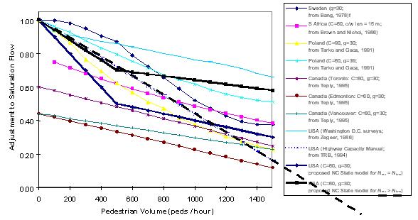 |
| Figure 11: Comparison of A pbT with other adjustment factors for pedestrians. |
TABLE 11 Proposed Adjustment Factor for Radius Effects on Right Turns (fRT)
| PRTa |
f RT |
PRT |
fRT |
P RT |
fRT |
| 0.00b |
1.000 |
;0.35 |
;0.948 |
0.70 |
0.895 |
| 0.05 |
0.992 |
0.40 |
0.940 |
0.75 |
0.888 |
| 0.10 |
0.985 |
0.45 |
0.932 |
0.80 |
0.880 |
| 0.15 |
0.978 |
0.50 |
0.925 |
0.85 |
0.872 |
| 0.20 |
0.970 |
0.55 |
0.918 |
0.90 |
0.865 |
| 0.25 |
0.962 |
0.60 |
0.910 |
0.95 |
0.858 |
| 0.30 |
0.955 |
0.65 |
0.902 |
1.00 |
0.850 |
NOTE: fRT= 1.0 - PRT(0.15) 0.0
≤ PRT≤ 1.0
a proportion of right turns in lane group
b no right turns from the lane group
|
TABLE 12 Existing and proposed saturation flow adjustment factors for lane groups containing turning vehicles
Source of Impedance to Turning Vehicles
| Procedure |
Movement |
Radius |
Opposing Vehicles |
Pedestrians |
Bicycles |
| Existing |
Left-Turn |
fLT |
fLT |
ignored |
ignored |
| Right-Turn |
fRT |
N/A |
fRT |
1 bike = 1 ped |
| Proposed |
Left-Turn |
fLT |
fLT |
fLpb a |
ignored |
| Right-Turn |
fRT a |
N/A |
fRpb a |
fR pb a |
|


