May 3, 2005
A team of Mayes Testing Engineers (MTE) inspectors arrived at Oakland Bay Bridge project site offices on April 19, 2005 to perform an independent evaluation of pile connection plate welds in the Pier Footing Structure E4W. The welding in this structure was recently stopped in order to investigate allegations of substandard welds in the pile head connection plates. We understand that there were allegations of welding over gross defects such as cracks and excessive porosity and welding outside of approved parameters. A Scope Of Work dated April 13, 2005 (see Appendix A) was developed by FHWA prior to our arrival. MTE personnel and its sub consultants provided all of the services described, except that cutting for removal of weld test samples was by KFM welders under direct supervision by MTE and FHWA. MTE provided all Scope Of Work items listed, except for Items 5 and 6, which will be provided by consultant Roy Teal under separate contract with FHWA. Roy Teal also prepared the "Weld Sample Removal Procedure" dated April 21, 2005 (see Appendix B), which included videotaping and photography procedures used to document sampling and testing activities.
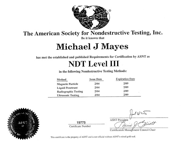
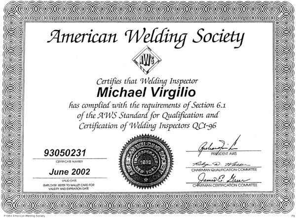
The MTE evaluation team was lead by Michael J. Mayes, P.E. who is a Welding Engineer and NDE Level III with over 25 years of experience with welded structures. MTE inspectors Mark Vassallo and Mike Virgilio performed visual and magnetic particle inspection on welds selected by the FHWA. Vassallo and Virgilio are both AWS Certified Welding Inspectors and NDE Level II's. Laboratory testing was conducted by Jay Dwight, who is a Welding Engineer with over 35 years of experience with weld testing. Resumes for these individuals are included in the Appendix of this report.
We have included the following in this report:
Review of Welding Procedures
Review of QA/QC Inspection Procedures
Visual Weld Inspection and Magnetic Particle Examination Procedures and Results
Specimen Testing and Tracking Procedure
Macroetch Test Results
Attachments
Appendixes
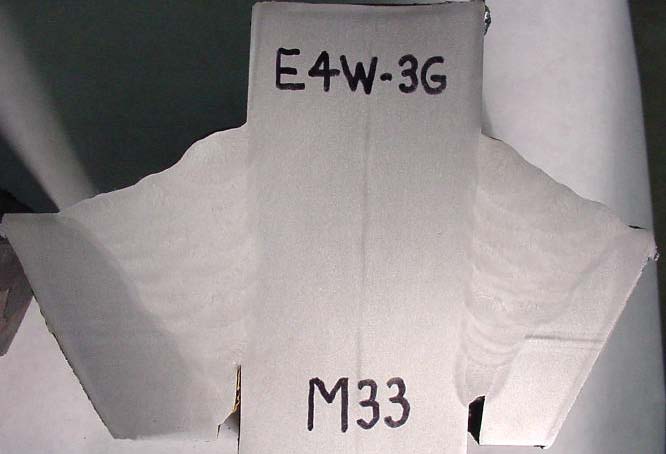
On April 19, 2005, the MTE team attended confined space training, in order to enter the footing pier spaces, and then toured Pier Footing Structure E4W (See Figure 1). Visual inspection and magnetic particle examination was conducted on April 22, 21 and 22, 2005. Weld samples 2B, 3G and 5D were removed from the structure on April 22. Crated samples were driven by Virgilio and Vassallo to the testing laboratory in Washington arriving on April 23. Saw cutting began on April 24 and macroetch samples were completed April 26, 2005. All field testing and weld sample removal was videotaped. All field testing, weld sample removal and lab testing was observed by representatives of FHWA, Caltrans and the Contractor, KFM. Video and digital photography was used to document all activities and chain of sample custody.
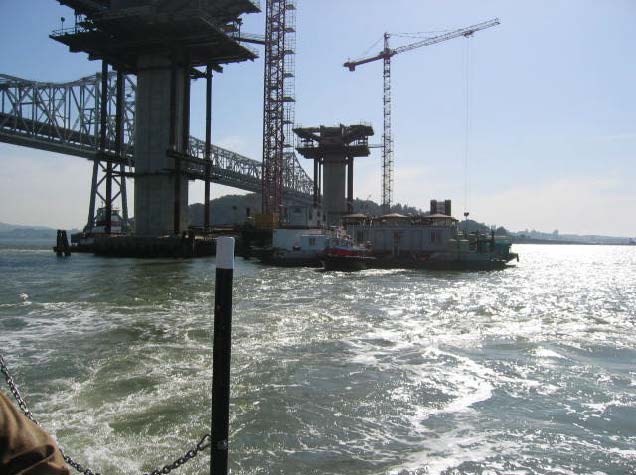
Figure 1: Pier footing at E4W
The field and laboratory work performed by the Mayes Testing Engineers evaluation team shows excellent workmanship in the pile connection plate welds in pier footing structure E4W. There was no evidence of gross flaws. In fact, there was no evidence of any unacceptable flaws in any of the samples tested. The weld cross-section significantly exceeds the minimum design requirements. The weld average cross-section depth (weld effective throat) is 25 percent greater than design requirements and the weld cross-section also shows a very regular pattern of weld bead deposition indicating a consistent and controlled welding process.
Respectfully Submitted,
MAYES TESTING ENGINEERS, INC.
Michael J. Mayes, P.E.
Welding Engineer/NDE Level III
Welding Procedures
QA/QC Inspection Procedures
E4W Connection Plate Welds
Nondestructive Testing Results
Magnetic Particle and Visual Examination Procedures
Magnetic Particle and Visual Examination Results
Weld Sample Removal and Testing
Weld Sample Removal
Sample Testing Procedures
Scope of Work
Weld Sample Removal Procedure
MTE Magnetic Particle Examination Procedure
Personnel Resumes
In order to better understand the welding process and project inspection requirements the following documents were requested from Caltrans:
Project Plans and Specifications for pier footing welded structures
Welding Procedure Specifications and Welding Procedure Qualification Records
Sample Welder Qualification Records
Shrinkage and Distortion Plan for Pile Head Connection Plates
The pile head connection plate weld connects the pile to the footing box structure (See Figure 2). There are eight connection plates per pile and each plate is connected with four welds (See Figures 3 and 4). The welds are detailed on the design drawings as partial penetration type welds with a reinforcing fillet weld.
The piles are numbered 1 through 6 beginning with the northeast pile identified as Pile No. 1 with sequential numbering in a clockwise direction. Within each pile, pile connection plates are lettered "A" through "H" with the northeast plate identified as Plate "A" with sequential lettering in a clockwise direction (See Figures 2 and 3 for identification). Using this convention each pile connection plate has a unique identification (eg 1A, 1B, etc).
The weld symbol on the design drawings requires minimum 31 mm groove depths to be cut in the pile wall and pile sleeve with a total effective throat requirement for the weld to be 40 mm. The effective throat dimension is the thinnest thickness dimension of the final welds (See Figure 5). The contractors procedures show that a 35 mm groove depth was actually used to assure that the effective minimum throat was obtained and to remove the ultrasonic verification requirement of root depth.
The Shrinkage and Distortion Plan also allow shims to be placed below the bevel in root gaps that are measured to exceed 3 mm. If root gaps exceed AWS D1.5 tolerances, than "weld buttering " can be used to close gap to acceptable tolerances. Figure 5 shows illustration of shimming and weld buttering.
The project specifications require that welding meet AWS D1.5—96 Bridge Welding Code requirements. The welding procedures used for this joint were qualified by testing. The welding process used for the pile connection plate welds was a gas-shielded flux cored or welding (FCAW) process. Shielded metal arc welding (SMAW) process was used for "weld buttering" and root pass welding. Welding procedure qualification tests show tensile strengths and toughness results well in excess of AWS D1.5 requirements. Welders were also qualified to AWS D1.5 with witnessing of qualifications by Caltrans representatives.
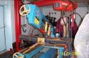
The welds were placed in the vertical position using automated welding equipment guided by a track attached adjacent to the weld groove (See Figure 6). Once the welding equipment is set up and aligned, it could be expected that welding parameters would be very consistent compared with conventional hand operated welding equipment. Preheat and interpass temperature is continuously maintained with the use of electrical strip heaters mounted adjacent to the weld.
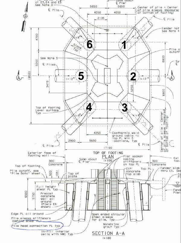
Figure 2: Pier footing structure plan view and elevation view for skyway structure pile head.
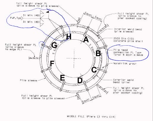
Figure 3: Plan view of pile head connection plate (8 locations) with welding symbol.
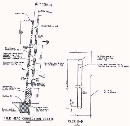
Figure 4: Pile head connection details.
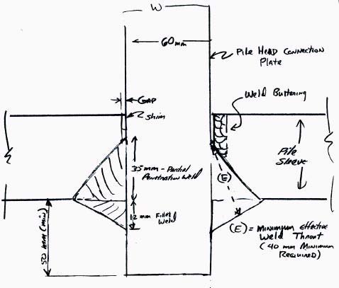
Figure 5: Pile head connection plate weld illustration.
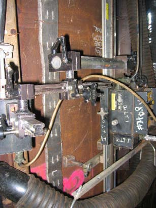
Figure 6: Automated FCAW equipment and electric heat strips at partially welded pile connection plate weld.
The scope of our evaluation was to evaluate welds selected by FHWA. We did not review quality control or quality assurance records. We understand that magnetic particle examination and visual examination was performed on these joints as required by the project specifications and the contractor's quality control procedures. These procedures required visual examination of weld fit-up prior to welding including any shimming or buttering. Each root pass was to be subjected to magnetic particle examination. The in process welding was to be inspected by quality control inspectors with each welder to be inspected at least twice per hour. Magnetic particle and visual examination was performed on final weld surfaces. These inspection procedures exceed the minimum AWS D1.5 Bridge Code Requirements which require only a minimum of 10% magnetic particle examination on the surfaces of main member partial penetration and fillet welds.
The project specifications require that the quality of the pile head connection plates weld be in accordance with AWS D1.5 criteria for "Tension Welds". This criteria allows no cracks and defines acceptable weld profiles, weld undercut limits, porosity limits and maximum limits for "fusion type discontinuities. For these welds the D1.5 criteria would allow a maximum 13 mm long "fusion type discontinuity" (such as a slag inclusion) every 115 mm along the length of the weld without repair. One porosity hole in the weld surface is allowed every 100 mm or six porosity holes in 1200 mm of weld length before repair is required, as long as the individual pore hole diameter does not exceed 2.4 mm.
We understand that each 1700 mm long weld pass took 15 to 20 minutes to complete welding and cleaning. Setting up the welding equipment for the next pass took another 15 to 20 minutes. Depending on the joint gap and variance in actual welding variables (a range of amperage, volts and travel speed is allowed by the procedure) there were reported to be 17 to 23 passes per completed weld. Another variable that would affect the final number of passes would be any grinding performed on intermediate passes to remove slag or to smooth surface profile prior to welding next weld pass.
We understand that all welding work was abruptly halted on pier footing structure E4W during the week of April 11, 2005. At the time of our evaluation, many of the weld joints were completely filled, several were only partially welded and a few were only fit-up. Many of the completed welds still had weld tabs in place. Other weld terminations had weld tabs removed but grinding to remove torch cuts had not been done. Several weld surfaces had been marked for in process repairs such as excessive weld reinforcement, undercut and under fill.
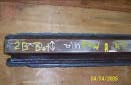
Welding equipment and strip heaters were still placed on the weld joints. All of the welds had evidence of inspection; with inspection notes, inspector initials and dates marked on the steel plates adjacent to the welds (See Figure 7). Lighting in the welding spaces and access to all weld surfaces was very adequate.
It was clear that final Quality Control and Quality Assurance inspection had not been completed on any of the pile connection plate welds.
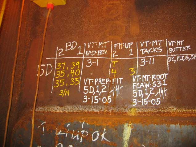
Figure 7: Quality control marks adjacent to pile connection plate weld 5D.
On April 20 to 22, 2005 visual and magnetic particle testing was performed on the Oakland Bay Bridge at Pile Footing E4W. Inspection was performed on partial penetration welds of pile connection plates that connect the pile to the pile footing sleeve. Mayes Testing Engineers (MTE) was instructed by FHWA to perform visual and magnetic particle testing of the welds in the existing (as is) condition to evaluate the weld quality and to identify any gross defects associated with allegations.
The method of inspection was Magnetic Particle Examination and Visual Inspection to identify any weld flaws. The magnetic particle testing procedure was AC yoke method; the DC yoke method was used to further explore any questionable indications. MTE Magnetic Particle Procedure No. MTE-AWS was followed (See Appendix). The welds are at various stages of completion and none of the welds had been final inspected by Caltrans QA or Contractor QC inspectors. MTE was directed by FHWA to perform inspection on the sleeve side of pile 2, 3, and 5 to provide a 25% inspection of the total pile head connection plate welds in Pile Footing E4W.
The magnetic particle testing (MT) revealed no rejectable flaws on the weld surfaces. We found two minor MT indications on the weld surfaces that were removed by light grinding [all grinding to resolve MT indications was performed by Mayes Testing Engineers inspectors (See Figures 14 and 15)]. There are several discontinuities resulting from work that is not yet complete. Since the work was abruptly stopped, the weld joints are in various states of completion, ranging from fit-up to completed welds. There are several areas on the weld surfaces that were previously marked (by KFM QC?) for grinding and or further welding to meet AWS D1.5 weld profile requirements. It was clear to us that, although in process inspection was evident, most of the welds had not had final inspection. Most of the discontinuities that were found were related to top and bottom weld termination at the access holes. The contractor uses and removes weld tabs at the weld terminations. Weld tabs are commonly used on welds such as these to insure that starts and stops at the end of the joint are removed. After weld tab removal there is quite a bit of grinding required to remove torch cuts and tab welds from base metal and pile weld surfaces. There are several cycles of grinding and MT, and sometimes even weld repair at these weld ends to remove notches, incomplete fusion and occasional small cracks (See Figures 8, 9, 10, 11 and 12). These procedures are typical for these types of weld joints.
The welds at removal site 2B had tab removal and surfaces of weld termination previously completed before our inspection. The welds at removal sites 3G and 5D had previously had welds tabs removed but weld ends and adjacent base metal were still in a rough flame cut condition. It was decided to allow KFM welders complete grinding of these surfaces under supervision of FHWA and MTE representatives so that weld specimens would be representative of completed welds and so that weld terminations could be examined with MT before removal. After contractor grinding was complete, Mayes Testing Engineers inspectors performed MT examination of the entire weld including weld terminations at 2B, 3G and 5D. Further grinding of weld terminations at the tops of 3G and 5D was performed by Mayes Testing Engineers to remove MT indications (See Figures 11 and 12). All MT indications were removed by grinding to depths that did not exceed limits allowed by project specifications. All MT and grinding at the three removal locations was performed with continuous observation by KFM QC representatives and Caltrans QA representatives along with complete video documentation (See Figure 13). All parties agreed that the resulting weld termination surfaces of samples to be removed were typical of production welds.
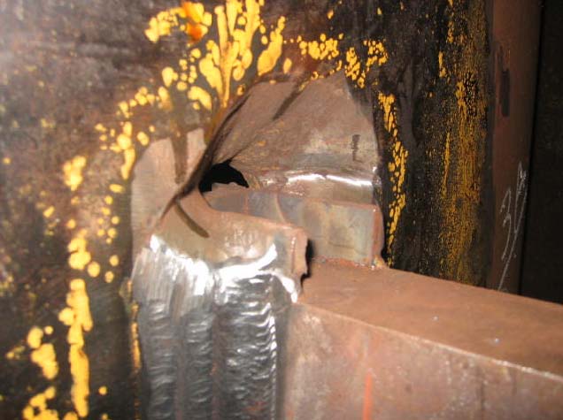
Figure 8: Weld tabs in place at top of pile connection plate weld.
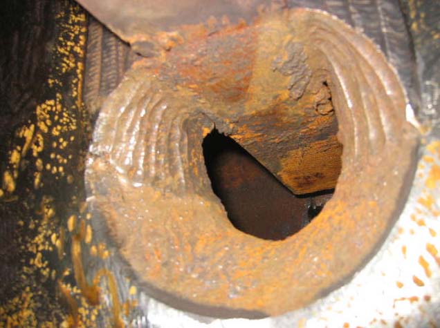
Figure 9: Bottom of pile connection plate weld, after weld tab removal, before grinding.
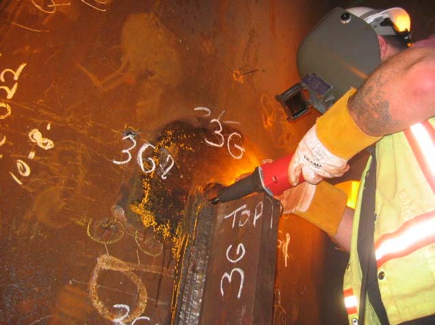
Figure 10: Grinding by MTE inspector Mike Virgillio to investigate magnetic particle indications at tab removal sites at location 3G.
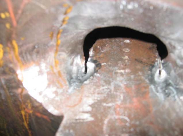
Figure 11: Tab removal site at location 3G after exploratory grinding. Magnetic particle indications no longer appear.
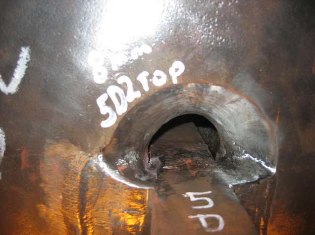
Figure 12: Top of pile connection plate weld at location 5D after grinding magnetic particle indications at tab removal sites.
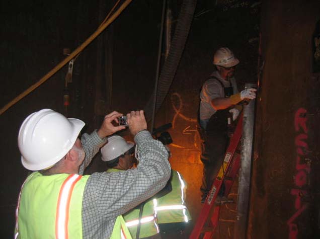
Figure 13: Video and photo documentation during magnetic particle examination.
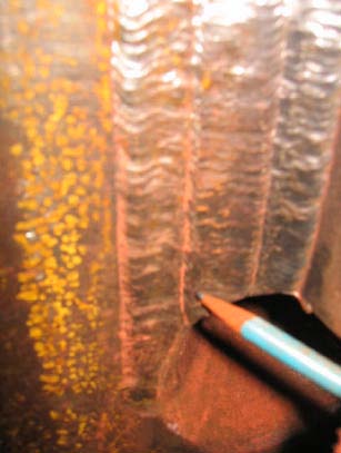
Figure 14: Magnetic particle indication at pile connection plate weld location 2C (Weld 2), between weld beads. Indication removed by light grinding, no flaw detected.
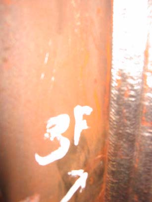
Figure 15: Magnetic particle indication at pile connection plate weld 3F in connection plate. Indication removed by light grinding, no flaw detected.
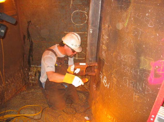
Figure 16: MTE inspector Mark Vasallo performing magnetic particle examination on pile head connection weld 2-B in Pier Footing Structure E4W.
The examination of 24 pile connection plate welds in pier footing structure E4W found no rejectable flaws, except for several items marked for in-process repair such as undercut, under fill, and grinding to improve surface profiles. There are several welds with Magnetic Particle indications at tab removal sites but these are located on areas that were not complete.
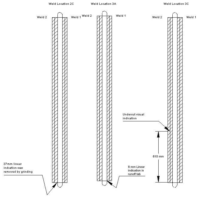
The results of the magnetic particle and visual performed on the welds in pile 2, 3, and 5 are as follows. Where indications were found they are detailed in the sketches below.
| 2A | Weld run off tabs have been removed, and ground. No relevant magnetic particle indications were noted. |
|---|---|
| 2B | Weld run off tabs have been removed, and ground. No relevant magnetic particle indications were noted. |
| 2C | Weld run off tabs have been removed, but not ground. One 37 mm indication was removed by grinding from Weld 2. No further relevant magnetic particle indications were noted. |
| 2D | Weld run off tabs have been removed, and ground. No relevant magnetic particle indications were noted. |
| 2E | Weld run off tabs have been removed, but have not been ground. No relevant magnetic particle indications were noted. |
| 2F | Weld run off tabs have been removed, and ground. No relevant magnetic particle indications were noted. |
| 2G | Weld run off tabs have not been removed or ground. No relevant magnetic particle indications were noted. |
| 2H | Weld run off tabs have been removed, and ground. No relevant magnetic particle indications were noted. |
| 3A | Weld run off tabs have not been removed, but were ground. One 8 mm linear indication was found in the run off tab area by magnetic particle testing. |
| 3B | Weld run off tabs have been removed, and ground. No relevant magnetic particle indications have been noted. |
| 3C | Weld run off tabs have been removed but not ground. Linear indications were detected in the top radius at the weld termination and at 610 mm from bottom in Weld No. 2 |
| 3D | This weld is partially complete; the throat is approximately ½ of the weld preparation depth. Magnetic particle testing was performed on the first 150 mm of weld length at the bottom of the weld. No relevant indications were found. |
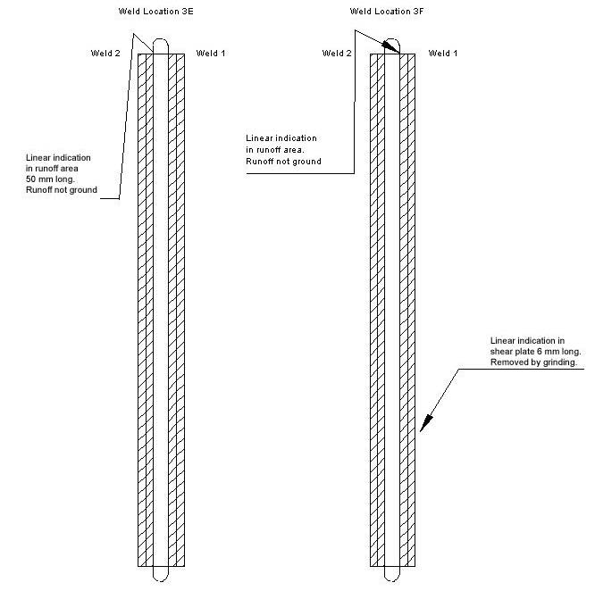
| 3E | Weld run off tabs have been removed, and ground. Weld No. 2 has an underfilled condition in a weld stop. Linear indications 50 mm long were detected in the weld run off tab area by magnetic particle testing. |
| 3F | Weld run off tabs have been removed, and ground. Linear indications 50 mm long were detected in the weld run off tab area by magnetic particle testing. Linear indications 6 mm long were detected in the connection plate 500 mm from the bottom on Weld No.1 side. These indications were removed by grinding. |
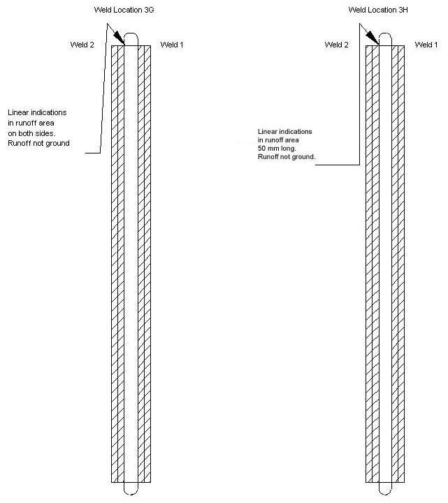
| 3G | Weld run off tabs have been removed, but not ground. Linear indications 50 mm long were detected in the weld run off tab area by magnetic particle testing. |
| 3H | Weld run off tabs have been removed, but not ground. Linear indications 50 mm long were detected in the weld run off tab area by magnetic particle testing. |
| 5A | Weld run off tabs have been removed, but not ground. No relevant magnetic particle indications were noted. |
| 5B | Weld run off tabs have not been removed, but were ground. No relevant magnetic particle indications were noted. |
| 5C | Weld run off tabs have not been removed or ground. No relevant magnetic particle indications were noted. |
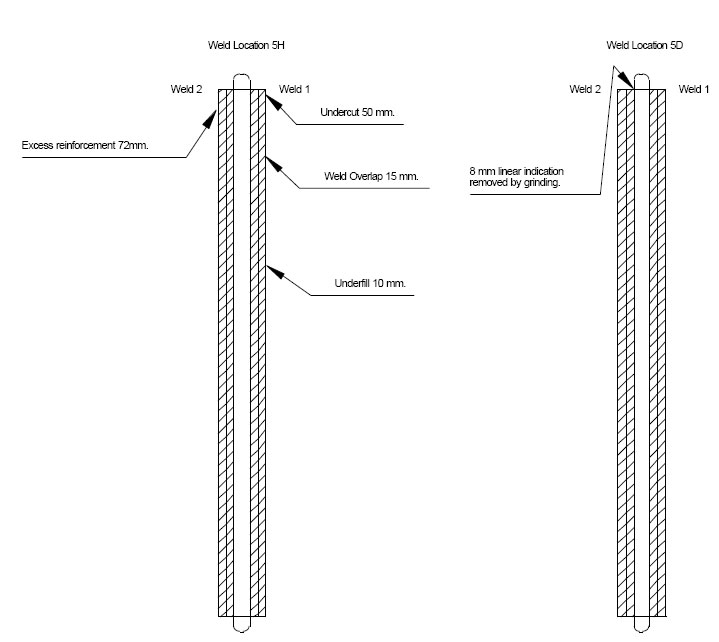
| 5D | Weld run off tabs have been removed, and ground. One 8 mm linear indication was removed by grinding from Weld No. 2 run off tab area. No other relevant magnetic particle indications have been noted. |
| 5E | Weld run off tabs have not been removed, but were ground. No relevant magnetic particle indications were noted. |
| 5F | Weld run off tabs have not been removed, but were ground. No relevant magnetic particle indications were noted. |
| 5G | Weld run off tabs have been removed, and ground. No relevant magnetic particle indications were noted. |
| 5H | Undercut in Weld No. 1 at the top end 37 mm long, 15 mm length of overlap in Weld No.1, 10 mm of underfill in Weld No. 1. Weld No. 2 has 72 mm of excess weld reinforcement at the top end. No relevant magnetic particle indications were detected. |
The following sketches are of welds where indications were detected as noted above.
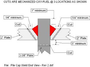
Several meetings were held with FHWA and Caltrans to discuss sample size and removal procedures. It was decided to remove three entire pile connection plate welds. Two locations, 5D and 3G were chosen, based on weld quality allegations. A third location 2B was randomly chosen. The welds at 5D while meeting AWS D1.5 minimum surface profile requirements showed the poorest surface profile of any weld in the E4W footing structure.
All three welds were taken from the pile sleeve side of the connection as there were apparently no allegations attributed to the pile side of the connection.
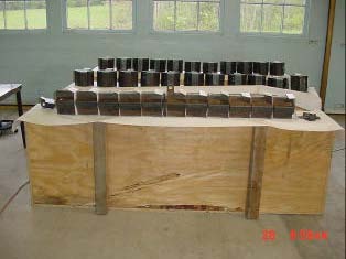
The entire weld and adjacent base metal was removed from each location. An automated gas cutting torch was used. Weld samples were removed from the pile sleeve and were immediately placed into individual wooden crates. Crates were taken by boat to shore and were loaded into a Mayes Testing Engineers (MTE) truck to be transported to the testing laboratory. Sample removal was continuously observed by MTE inspectors and FHWA representatives (See Figures 17, 18 and 19).
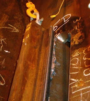
Figure 17: Removal of weld sample 5D.
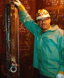
Figure 18: Sample 5D removed.
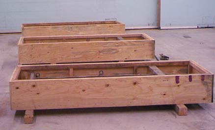
Figure 19: Crated Samples as received at laboratory.
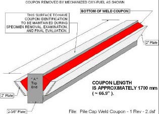
Prior to sample removal an FHWA "Specimen Testing and Tracking Procedure" (See attached) was developed. It was determined that each 1700 mm long weld would be cut into eleven 152 mm long specimens. Each specimen was to be machined, polished and etched on one end. Etching will show weld beads, depth of weld penetration and any weld flaws if present.
The six-inch specimen length would also allow possibility for weld tensile test and toughness testing. Other nondestructive tests such as ultrasonic and radiography were considered for this evaluation. Since only visual and magnetic particle examination were required by the contract documents and the AWS D1.5 Bridge Welding Code, it is not appropriate to subject these welds to ultrasonic and radiographic standards typically applicable to complete penetration welds. The D1.5 code does not contain testing procedures on acceptance criteria for utilizing radiography or ultrasonic techniques on partial penetration welds. The geometry of the pile connection plate welds would require specialized techniques and nonstandard procedures to apply radiography and ultrasound to these welds. It was determined that the best way to "look inside" these welds was to cut them out and cross-section them.
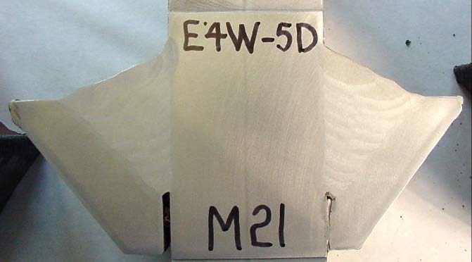
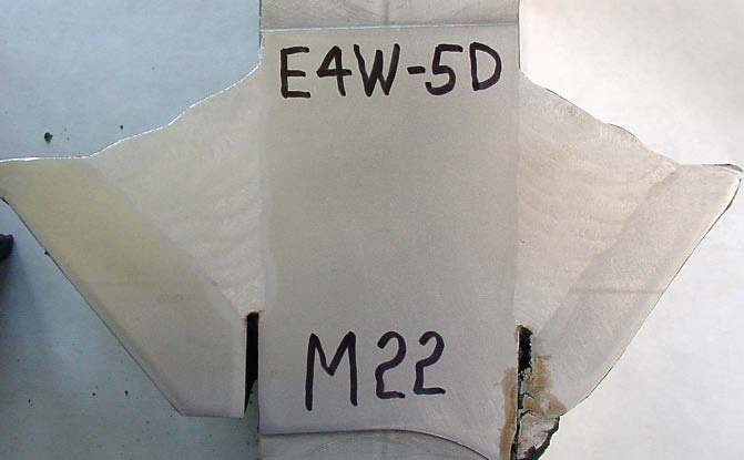
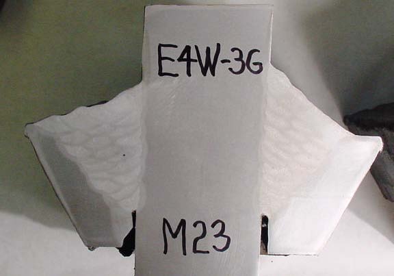
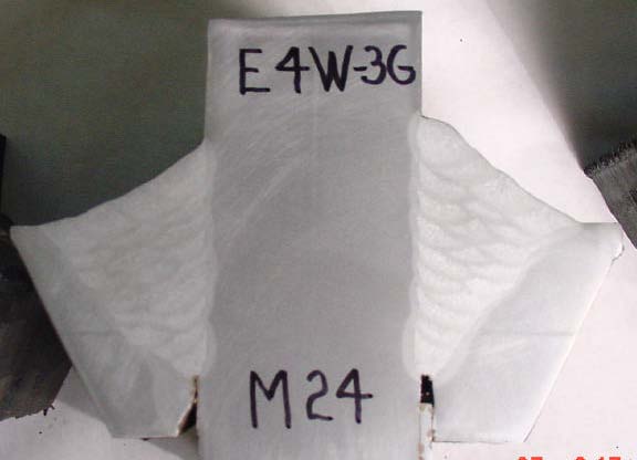
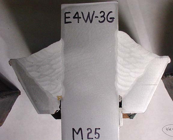
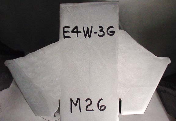
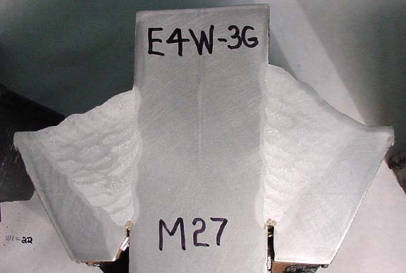
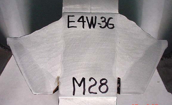
After receiving the sample in the lab, the saw cut lines were marked on the weld lengths. A sample identification was placed on each six-inch piece. The weld terminations at the top and bottom were cut off to provide square ends for machining. There were a few extra thin slices that had to be removed due to saw cutting problems, broken blades or uneven surfaces (See Figure 20). All sample pieces have been retained. Figures 21, 22 and 23 show entire weld lengths of each sample after saw cutting.
 |
U.S.DEPARTMENT OF TRANSPORTATION FEDERAL HIGHWAY ADMINISTRATION CALIFORNIA DIVISION |
|||
Specimen Testing & Tracking Procedure |
||||
STEP 1 Receipt |
 |
RECIEVE ( 3 ) COMPLETE WELD SAMPLES WITH CUT LOCATIONS AS SHOWN IN STEP FIGURE 1 AND AS DESCRIBED IN THE FHWA WELD SAMPLE REMOVAL PROCEDURE. THE LAB MANAGER SHALL SIGN & DATE FOR RECEIPT OF THE THREE ( 3 ) SAMPLES. LAB MANAGER SHALL ASSURE THAT SAMPLES ARE SECURE WITH DIGITAL PHOTOS SHOWING THE AS RECEIVED CONDITION. |
||
STEP 2 Digital Photo Records |
 |
GENERATE AN " EXCEL FILE " with EMBEDED DIGITAL PHOTOS SHOWING THE ORIGINAL AS RECEIVED MARKINGS. TAKE CARE TO PRESERVE THE AS RECEIVED PAINT — STICK MARKINGS. |
||
STEP 3 Marking & Cutting Overview |
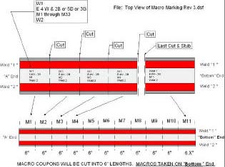 |
THE LAB SHALL PERMANENTLY MARK THE COUPONS BY DIE STAMP PRIOR TO SPECIMEN REMOVAL. THE LAB SHALL PRECISION SAW MACRO COUPON BLANKS AT THE CUT LINES SHOWN. |
||
STEP 4 Detail Marking LEGEND |
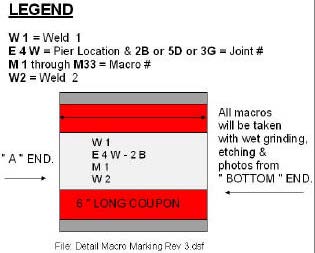 |
EACH MACRO WILL SHOW THE:
MARK EACH MACRO BLANK CORRESPONDING TO THE LEGEND IN STEP 4. |
||
STEP 5 Machine Wet Grind Wet Lap & Etch |
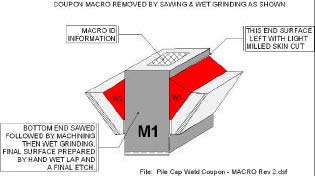 |
THE LAB SHALL PREPARE EACH MACRO END USING WET GRINDING. HAND WET LAP AFTER WET GRINDING. USE A 3 TO 5% NITAL ETCH ON THE WET LAPPED MACRO FACE. PRESERVE THE WELD DEPOSIT & BASE METAL METALLURGY. THIS SHALL INCLUDE A CLEAR GLOSS POLYURETHANE COATING ON THE MACROETCHED SURFACE. USE CARE SO AS TO NOT DISTURB THE MACRO COUPON NUMBERS. |
||
STEP 6 Macro Photo Features & Effective Throat |
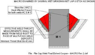 |
THE LAB SHALL TAKE A DIGITAL PHOTO OF EACH MACRO FACE SHOWING THE SPECIMEN NUMBER. THE MACRO SHALL SHOW THE WELD DEPOSIT, HAZ AND ADJACENT BASE METAL. THE MACRO # M1 through M33 SHALL BE CLEARLY VISIBLE ON THE DIGITAL PHOTO. THE EFFECTIVE THROATS WILL BE MEASURED USING A VERNIER CALIPER FROM UNAFFECTED WELD ROOT TO COVER BEADS NOT COUNTING EXCESS WELD REINFORCEMENT. |
||
| Record of Actual Macro Preparation on 2B, 5D & 3G. | ||||
STEP 7 Receive Locate Cut Lines Steel Stamp Saw Machine Wet Grind Final Etch |
|
2B RECEIVED IN SHIPPING CONTAINER. |
|
SAW, MACHINE & SURFACE GRIND MACRO BLANKS. |
 |
3G WITH 6" MACRO MARKS AND LEGEND AREA. | 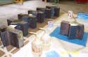 |
BLANKS READY FOR ETCHING. | |
 |
5D STEEL STAMPED AND READY FOR SAW. | 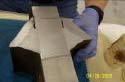 |
FINAL ETCH on Bottom End of Each Macro. | |
STEP 8 Test Summary Record |
LABORATORY TEST SUMMARY RECORD. See Laboratory Test Summary Records in Excel Format for Each Weld Location, 2B, 5D & 3G. The Excel File Names Are: Summary of Macro Test Results for E4W -2B M1 Through M11.xls |
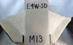
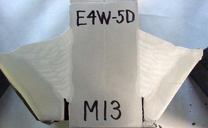
RECORD ALL DATA ON THE LABORATORY SUMMARY RECORD. THIS IS A TYPICAL COMPLETED SPECIMEN SHOWING MACRO NUMBER M13 FOR W2 & W1. W2 W1
|
||
| STEP 9 Packing & Storage & Shipping | Finish Macros Ready for Packaging
|
IMPOUND THE SPECIMENS FOR DISPOSITION BY FHWA. PACKAGE THE FINISH MACRO COUPONS IN 3 STORAGE BOXES. PROTECT THE MACRO SURFACES FROM SHIPPING DAMAGE USING 3 SEALED SHIPPING CONTAINERS. STORE THE SEALED CONTAINERS IN A SECURE, DRY ENVIRONMENT. THE 3 SEALED CONTAINERS SHALL BE SHIPPED TO: Federal Highway Administration |
||
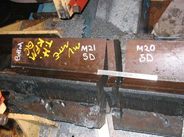
Figure 20: Short slice taken from Weld Sample 5D to correct uneven saw cut.
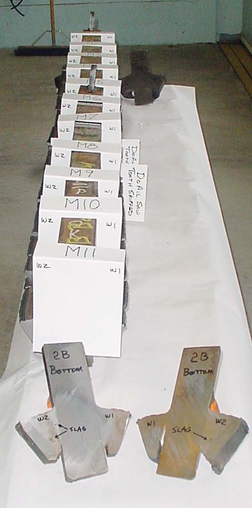
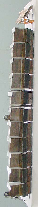
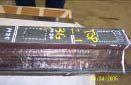
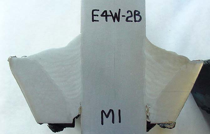
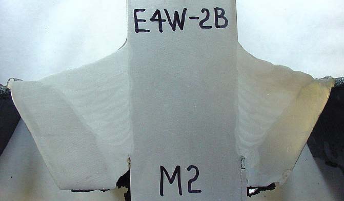
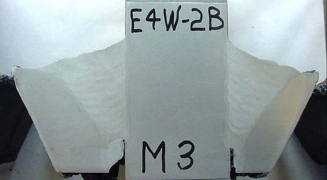
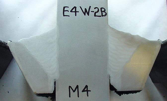
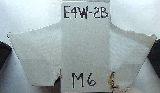
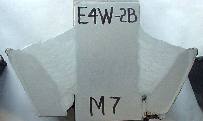
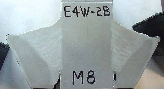
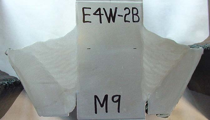
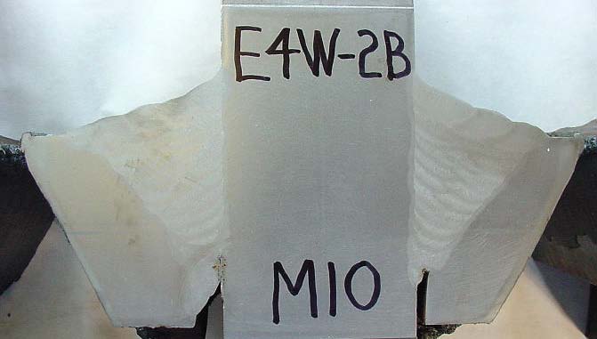
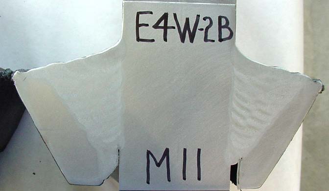
Figure 21: End and side views of weld sample 2B after saw cutting.
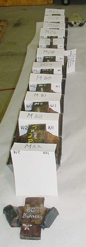
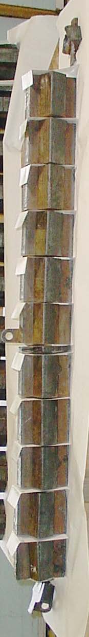
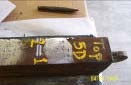
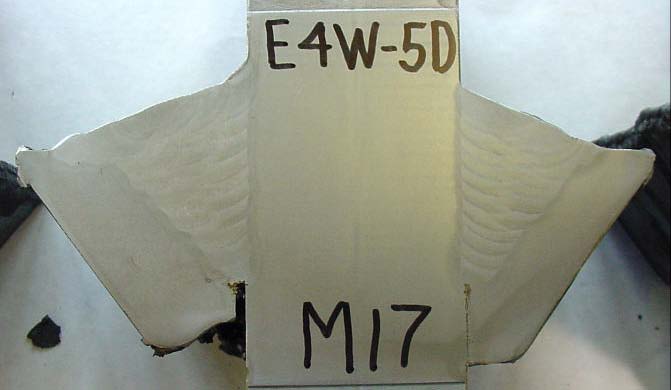
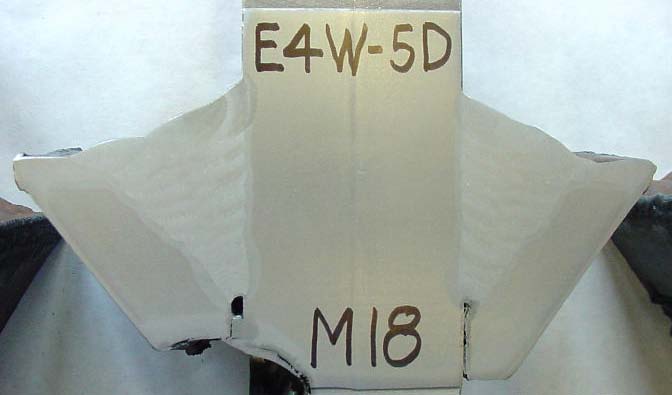
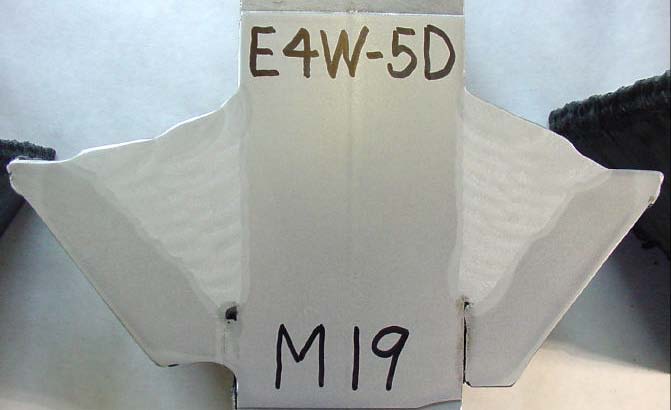
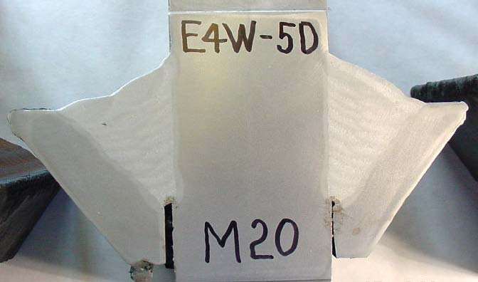
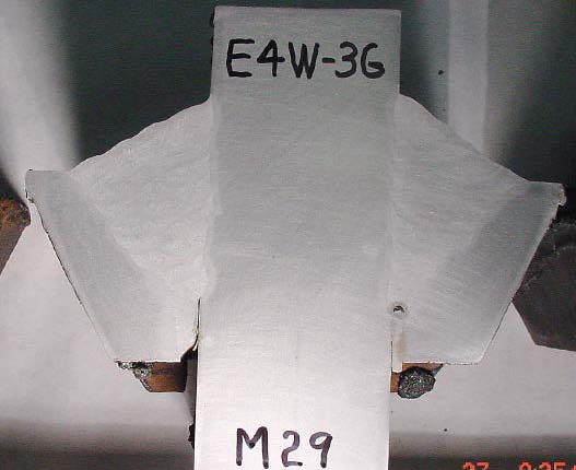
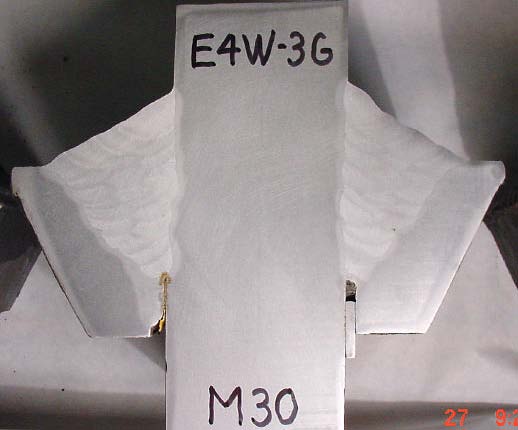
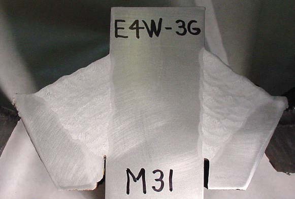
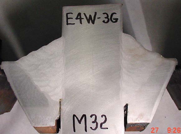
Figure 22: End and side views of weld sample 3G after saw cutting.
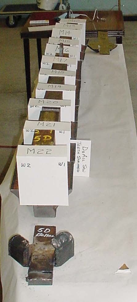
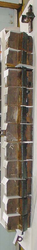
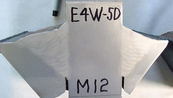
Figure 23: End and side views of weld sample 5D after saw cutting.
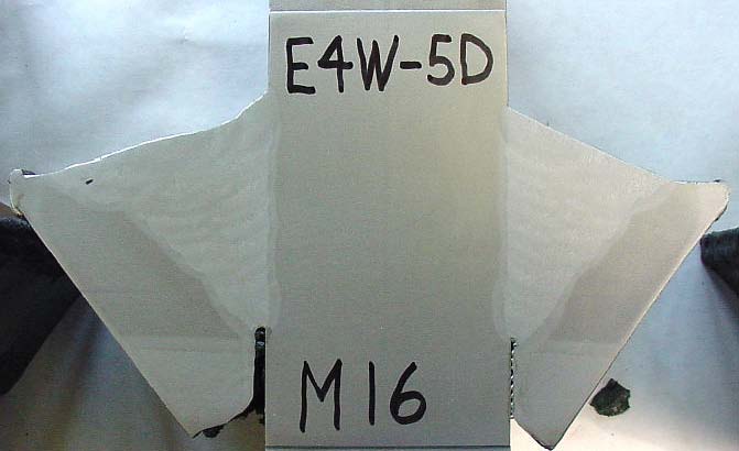
No rejectable weld flaws were found in any of the macro etch test samples. Samples M16, M20 and M28 show very small slag inclusions that would be well within acceptance of requirements per the AWS D1.5 Bridge Welding Code. Samples M23 and M30 show single pores of porosity that are acceptable per AWS D1.5 criteria.
Sample 2B had a slag inclusion which starts at the bottom termination of the weld (See Figure 24). This saw cut face was not intended to be macro etched. We saw cut another section 13 mm from the first cut. There was no evidence of the slag inclusion at the second saw cut. It is probable that this slag inclusion would have been removed when final inspection of weld tab removal site was performed. In any case the second saw cut verifies that the slag inclusion length was well within the AWS D1.5 acceptable limits.
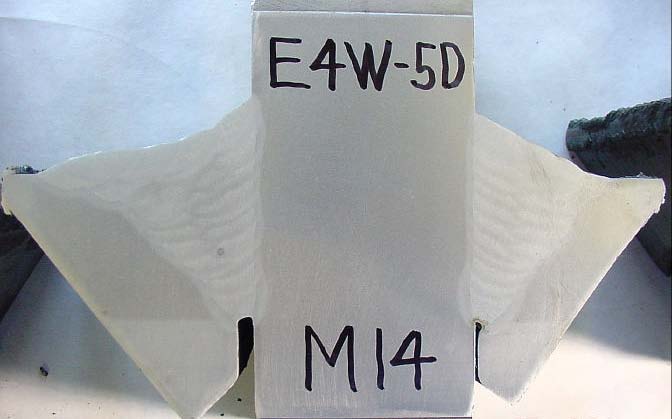
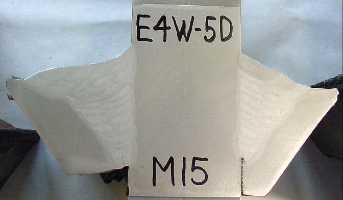
A crack was found in the root pass of Sample M15 (See Figure 25). This crack starts at the bottom of the root pass and continues to the center of the root pass. It is clear that this crack resulted from the flame cut sample removal process. If the crack happened during production welding it is most likely that the crack would start on the surface of the root pass and travel downward, due to weld shrinkage stresses. If this crack did happen during production welding, it would have never been detected by inspection since it did not extend to root pass surface. Note that the base metal at this location has been cut away by flame-cutting and that the heat affected zone (the lighter area) extended into the weld root. These conditions would have almost certainly caused this crack during flame cutting for sample removal.
The cross-sections show consistent weld bead deposition with total weld passes ranging from 16 to 24 depending on weld groove dimensions. Several of the weld passes are thinner profile which indicates grinding between passes by diligent welders (or mandates by diligent inspectors) to remove slag or to improve weld profiles before depositing next pass.
Many of the cross-sections show "weld buttering" and use of shims as described by the "Shrinkage and Distortion Plan."
The average depth of weld penetration (weld effective throat) is 51.5 mm. This average exceeds the 40 mm design requirement by over 25 percent.
The overall weld quality is excellent and greatly surpasses typical field welding quality that we have seen on similar structures.
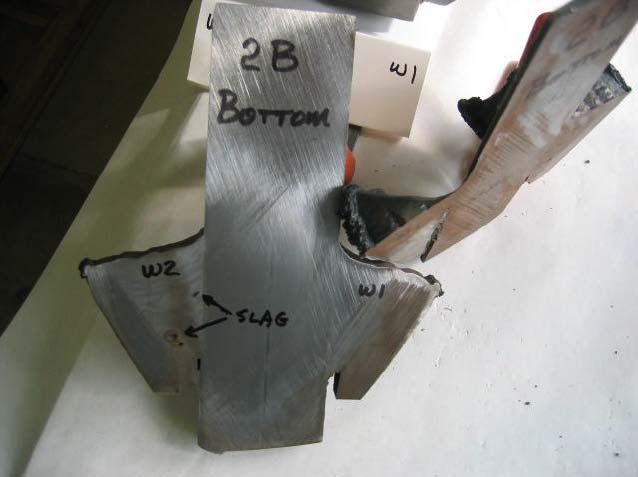
Figure 24: The bottom of the pile connection plate weld 2B. Slag inclusion found 3 mm from weld end. Another saw cut taken 13 mm from end showed no slag.
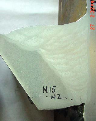
Figure 25: Sample M15 from Weld 2 in sample 5D. Note crack in root pass extending from bottom of root to middle of root. Dashed line shows boundary of heat affected zone from gas cutting during sample removal.
| Macro No. | Effective W1 Throat |
No. of Weld Beads W1 |
Effective W2 Throat |
No. of Weld Beads W1 |
Comment & Findings |
|---|---|---|---|---|---|
| M1 | 52 | 18 | 51 | 19 | No indications. |
| M2 | 53 | 18 | 52 | 21 | No indications. |
| M3 | 54 | 18 | 52 | 20 | No indications. |
| M4 | 52 | 21 | 53 | 18 | No indications. Macro is on "A" end. |
| M5 | 52 | 17 | 50 | 20 | No indications. |
| M6 | 51 | 17 | 51 | 22 | No indications. |
| M7 | 50 | 18 | 52 | 22 | No indications. |
| M8 | 50 | 18 | 51 | 22 | No indications. |
| M9 | 51 | 17 | 50 | 19 | No indications. |
| M10 | 52 | 17 | 49 | 19 | No indications. |
| M11 | 50 | 20 | 50 | 20 | No indications. |
| M12 | 49 | 20 | 50 | 19 | No indications. |
| M13 | 49 | 18 | 51 | 24 | No indications. |
| M14 | 49 | 17 | 49 | 22 | No indications. |
| M15 | 49 | 17 | 49 | 23 | One non-relevant indication in W1. This is a secondary crack from the flame - cut removal process. |
| M16 | 50 | 17 | 50 | 24 | One slag inclusion in W2. The approximate size is 2.3 x 0.5 mm. Acceptable per AWS D1.5 |
| M17 | 49 | 19 | 53 | 24 | No indications. |
| M18 | 50 | 17 | 48 | 19 | No indications. |
| M19 | 48 | 18 | 48 | 19 | No indications. |
| M20 | 48 | 20 | 45 | 18 | One slag inclusion in W2. The approximate size is 2.4 x 0.2 mm. Acceptable per AWS D1.5 |
| M21 | 48 | 17 | 48 | 18 | No indications. Short coupon due to saw blade damage. |
| M22 | 49 | 16 | 46 | 16 | No indications. |
| M23 | 55 | 19 | 52 | 21 | One porosity hole in W2. The approximate size is 0.8 x 0.4 mm. Acceptable per AWS D1.5. |
| M24 | 55 | 20 | 52 | 21 | No indications. |
| M25 | 54 | 21 | 53 | 19 | No indications. |
| M26 | 56 | 20 | 54 | 22 | No indications. |
| M27 | 56 | 20 | 54 | 18 | No indications. |
| M28 | 55 | 23 | 52 | 20 | One slag inclusion in W1. The approximate size is 2.0 x 0.3 mm. Acceptable per AWS D1.5. |
| M29 | 55 | 21 | 53 | 19 | No indications. |
| M30 | 55 | 18 | 54 | 19 | One porosity hole in W1. The approximate size is 0.4 x 0.3 mm. Acceptable per AWS D1.5. |
| M31 | 55 | 20 | 53 | 20 | No indications. |
| M32 | 55 | 18 | 54 | 18 | No indications. |
| M33 | 57 | 19 | 52 | 19 | No indications. |

April 13, 2005 @ 12:32 pm
"Scope of Work and Services for Independent Testing at SFOBB - Skyway"
Services to be provided by contractor:
American Society of Nondestructive Testing (ASNT) Level III certificate holder in Magnetic Particle Testing (MT).
Level II services in accordance with an approved written practice (by FHWA) developed in accordance with American Society of Nondestructive Testing (ASNT) in Magnetic Particle Testing (MT).
American Welding Society (AWS) Certified Welding Inspector (CWI) services.
Video taping and digital imaging of the test locations
Provide personnel and equipment to remove selected weld material and heat affected zone as determined by the FHWA.
Metallurgical examination using macro (visual) techniques for the selected weld samples.
Final report of investigation and presentation material.
Said services shall be in accordance with the contract documents and national standards and codes.
Specifications required:
The Consultant must demonstrate capability in AWS D1.5 code interpretation, and in destructive and nondestructive testing.
Must also demonstrate expert knowledge of structural steel bridges.
The Consultant shall be capable of meeting current industry standards including American Welding Society (AWS), Quality Control (QC-1)
American Society of Nondestructive Testing (ASNT) Recommended Practice - Society for Nondestructive Testing (SNT) - Technical Council (TO) - First Document (IA).
The Consultant shall provide equipment necessary to perform and interpret Magnetic Particle Testing (MT) and the sampling and testing of weld material as defined in the scope of work.
Location of work:
The Consultant shall be capable of delivering these services except for metallurgical lab evaluation (inspection, sampling and testing) on the SFOBB Skyway project site. Federal Aid Project AC1M-080-1 (085) 8N.
Scope of Work:
Non-destructive Testing:
Magnetic Particle Testing (MT) and Visual Examination of the weld cap passes (shear plates) at a minimum of 270 feet of weld in pier foundation E4W.
Destructive Testing:
A final report outlining the findings, inspection procedures, conclusions,and a statement to verify that the contractual requirements for the welding have been met.
The investigation, sampling, testing and inspection shall be complete within 2 weeks of contract execution and final report and photos, video,and final presentation no more than 5 days after completion of the fieldwork.
Independent Review of the QC-QA welding inspection process in Pier 5W when work is available. (This is anticipated to occur at a later date).
The final report of the independent review of the QC-QA welding inspection in Pier E5W to include findings, inspection procedures, conclusions to determine if the QC-QA procedures are adequate. This report to be completed in three weeks after inspection is completed.
U.S. DEPARTMENT OF TRANSPORTATION
FEDERAL HIGHWAY ADMINISTRATION
CALIFORNIA DIVISION
650 Capitol Mall, Suite 4-100
Sacramento, CA. 95814
San Francisco Oakland Bay Bridge
PILE HEAD at PIER E4W
WELD SAMPLE REMOVAL PROCEDURE
Prepared by Roy Teal, Inc.
April 21, 2005
Mayes Testing Engineers, Inc.
Nondestructive Examination Standard
Magnetic Particle Examination
Procedure No. MT-AWS
Revision No. 2
Original Issue Date: July 1, 1991
Authorized by: Date:
Table of Contents
1.0 Scope
2.0 References
3.0 Precautions for personnel safety
4.0 Personnel
5.0 Equipment and Materials
6.0 Surface Preparation
7.0 Technique
8.0 Records
9.0 Nondestructive examination subcontractors10.0 Standards of Acceptance
Figure 1: Weld quality requirements for discontinuities occurring in tension welds
Figure 2: Weld quality requirements for discontinuities occurring in compression welds
Figure 3: Weld Quality Requirements for Tension Joints in Bridges
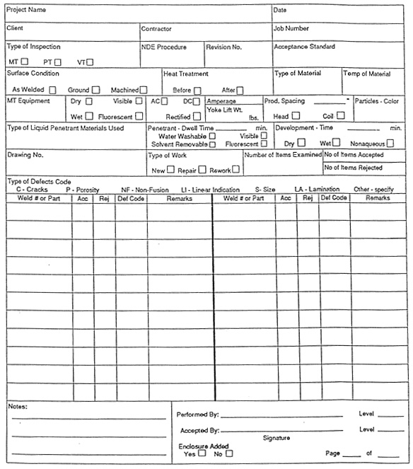
Exhibit 1: Nondestructive Examination Report form
Revision # Date Revision 1 11/l5/04 Updated 2 12/27/04 Add AWS D1.5 References
1.0 Scope
1.1 This standard provides the procedure to be used as a minimum for dry, continuous method, magnetic particle examination of welds and/or adjacent base materials in accordance with AWS D1.1 and AWS D1.5 for New Building, New Bridges and Tubular Structures.
1.2 This standard shall be used as a procedure by Mayes Testing Engineers, Inc. (MTE) when performing magnetic particle examination.
2.0 References
Structural Welding Code, AWS D1.1, latest Edition.
Structural Bridge Code, AWS D1.5, latest Edition.
Standard Practice for Magnetic Particle Examination, ASTM E709.
Standard Practice for Determining the Qualification of Nondestructive Testing Agencies, ASTM E543.
American Society for Nondestructive Testing, Recommended Practice, SNT-TC-1A
MTE Nondestructive Examination Standard, NDE Personnel Qualification PQ-1.
3.0 Precautions for Personnel Safety
3.1 The equipment and/or materials used in this standard shall be utilized in afashion to ensure full compliance with national, state and local laws governing safety.
4.0 Personnel
4.1 Personnel performing magnetic particle examinations to this standard shall be qualified and certified as an NDE Level I, II or III in the magnetic particle method, in accordance with the applicable MTE Personnel Qualification Standard, PQ-I, which has been developed from guidelines provide by the American Society for Nondestructive Testing Recommended Practice SNT-TC-1A.
4.2 All NDE subcontractor personnel performing magnetic particle examination to this standard shall be qualified and certified as an NDE Level I, 11 or III, in the magnetic particle method, to a personnel qualification standard developed from guidelines provided by the American Society for Nondestructive Testing Recommended Practice, SNT-TC-1A.
4.3 Only MTE personnel certified NDE Level II or III shall perform final evaluations.
5.0 Equipment and Materials
5.1 Equipment
5.1.1 Magnetizing Units
5.1.1.1 Magnetizing units used for the prod method shall produce either direct or recertified current and shall have an ammeter that is visible and readable by the operator while performing the examination.
5.1.2 Prods
5.1.3 Yokes: Either electromagnetic or permanent magnet yokes may be used.
5.1.3.1 Magnetizing units for electromagnetic yokes shall be capable of producing alternating current, direct current, orboth.
5.1.4 Magnetic Particle Field Indicator: A magnetic particle field indicator as described in ASTM E709 may be used to determine the adequacy of the magnetic field.
5.2 Equipment Calibration
5.2.1 Frequency of Calibration: Each piece of magnetizing equipment shall be calibrated at least once a year, or after each time it has been subjected to major electrical repair, periodic overhaul, or damage. If equipment has not been used for a year or more, calibration shall be done prior to use.
5.2.2 Equipment with ammeters
5.2.2.1 Procedure - The accuracy of the unit's meter shall be verified annually by equipment traceable to a national standard. Comparative readings shall be taken for at least three different current output levels encompassing the usable range.
5.2.2.2 Tolerance - The unit's meter reading shall not deviate by more than 10% of full scale, relative to the actual current value as shown by the test meter.
5.2.3 Yokes: The magnetizing force of yokes shall be considered adequate if:
5.2.3.1 Each alternating current electromagnetic yoke has a lifting power of at least 10lbs. With a pole spacing of 2 to 4 inches.
5.2.3.2 Each direct current or permanent magnet yoke has a lifting power of at least 30lbs. With a pole spacing of 2 to 4 inches and 50Lbs with a pole spacing of 4 to 6 inches.
5.2.3.3 Each weight shall be weighed with a scale from a reputable manufacturer and stenciled with the applicable nominal weight prior to first use. A weight need only be verified again if damaged in a manner that could have caused potential loss of material.
5.3 Materials
5.3.1 The following magnetic particles or their equivalent shall be used: Magnaflux, No. 8A Red, No. 1 Gray, No. 2 Yellow, No. 3A Black, Uresco Magne-Tech UM-221 Red, UM-188 Gray, UM-255 Yellow
5.3.2 The color of the particles shall be selected to provide adequate contrast with the item being examined.
6.0 Surface Preparation
6.1 The surface to be examined may be in the as-welded, as-rolled, as-cast, or as-forged condition. However, if there are surface irregularities that could mask indications of unacceptable discontinuities, surface preparation by grinding, machining or other methods may be necessary.
7.0 Technique
7.1 Pre-cleaning
7.1.1 Prior to magnetic particle examination, the surface to be examined and all adjacent areas within at least 1 inch shall be cleaned to remove any dirt, grease, lint, scale, welding flux, weld spatter, oil, or other substance that could interfere with the examination.
7.1.2 Typical pre-cleaning agents that may be used are detergents, organic solvents, descaling solutions, paint removers, vapor degreasing, sand or grit blasting, and ultrasonic cleaning.
7.1.3 The surface to be examined shall be thoroughly dried before beginning the examination. Drying of the surface may be accomplished by normal evaporation or by using forced air.
7.2 Temperature
7.2.2 Magnetic particle examination shall not be done on the surface of parts whose temperature exceeds 600°F (315°C).
7.2.3 Magnaflux Corp., 8A red magnetic particle powder shall not be used on articles whose surface temperature exceeds 325°F.
7.3 Sequence of Operation
7.3.2 Magnetic particle examination shall be done by the continuous method; that is, the current shall be turned on, the magnetic particle powder shall be lightly dusted over the area being examined, the excess magnetic particle powder shall be removed using a gentle air stream, then the current is turned off.
7.3.3 The area under the examination must be observed during the application of the magnetic particle powder to detect the formation of indications,
Caution: The air stream used to remove excess magnetic particle powder must be controlled so that it does not disturb or remove lightly held powder patterns.
7.4 Methods
7.4.2 Prod Method
7.4.2.1 Prod spacing shall be a minimum of 3 inches and a maximum of 8 inches.
7.4.2.2 The magnetizing current shall be 100-125 amps per inch of prod spacing for sections 3/4 inch thick or greater. For sections less than 3/4 inch thick, amperage shall be 90-110 amps per inch of prod spacing,
7.4.2.3 The current shall be turned on after the prods have been properly positioned and turned off before they are removed from the component.
7.4.2.4 Copper tipped prods shall not be used when the open circuit voltage exceeds 25 volts.
7.4.3 Yoke Method
7.4.3.1 AC, DC or permanent magnet yokes shall be used.
7.5 Examination Coverage
7.5.2 At least two separate examinations shall be carried out on each area so the lines of flux in one examination are approximately perpendicular to the lines of flux in the other. A different means of magnetizing may be used for the second examination provided the resulting lines of flux are approximately perpendicular to those of the first method.
7.5.3 Examinations shall be conducted with sufficient overlap to assure 100% coverage at the established test sensitivity. For example:
7.5.3.1 When positioning prods or a yoke longitudinally along a weld, a minimum overlap of 1 inch shall be maintained between subsequent positions.
7.5.3.2 When positioning prods or a yoke transversely along the weld the spacing between subsequent positions shall be a maximum of 1/2 or prod or pole spacing or 3 inches, whichever is smaller.
7.6 Demagnetization
7.6.1 When required, the weld or component shall be demagnetized after completion of the examination in accordance with ASTM E709 and verified with a magnetic field strength meter.
7.7 Post Examination Cleaning
7.7.1 All surfaces shall be cleaned of magnetic particles after examination.
7.8 Interpretation of Results
7.8.1 Adequate illumination shall be provided to assure proper evaluation. The intensity of the visible light at the surface of the work piece under examination should be a minimum of 100 foolcandles (1000 Lux).
7.8.2 Discontinuities will be revealed by the retention of the ferromagnetic particles at or near discontinuities. All indications revealed by magnetic particle examination are not necessarily defects. Nonrelevant indications can be caused by excessive surface roughness, magnetic permeability variation, or contour changes which are not relevant to the detection of unacceptable discontinuities.
7.8.3 Any indications in excess of the acceptance standards, which are believed to be nonrelevant, shall be regarded as a defect and shall be re-examined to verify whether or not actual defects are present. Surface conditioning may precede the re-examination. Nonrelevant indications that would mask indication of defects are unacceptable.
7.8.4 Relevant indications are those that result from unacceptable mechanical discontinuities. Linear indications are those indications in which the length is more than three times the width. Rounded indications are indications that are circular or elliptical with the length less than three times the width.
7.8.5 Unacceptable defects shall be removed or reduced to an acceptable limit.
8.0 Records
8.1 The examinationshouldbe documented using the MTE Nondestructive Examination Report form.
8.2 As a minimum, the following must be recorded:
- MTE Project Number
- Welds or areas examined
- Weld joint or part identification
- Equipment (prod or yoke)
- Material (manufacturer and color)
- Examination procedure (standard) identification, revision number, and type of examination.
- Date of examination
- NDE Inspector's name and certification level
- Examination results
8.3 All records of magnetic particle examination shall be submitted to the appropriate MTE Level III or designee. These records shall be maintained in the MTE permanent job files.
8.4 A copy of the certification records for NDE Level I and Level II personnel, and copies of certification records for the NDE Level III examiner who certified the NDE Level I and NDE Level II personnel shall be maintained on file.
9.0 Nondestructive Examination Subcontractors
9.1 If NDE subcontractor procedures are used, they shall be submitted for review to a MTE Level III inspector before performing any examinations. These procedures shall be available at all times to the responsible individual at the jobsite while any examination is in progress.
9.2 The subcontractor's procedure shall be equivalent in all essential respects to this standard and shall be qualified to meet the referencing code section.
9.3 A MTE NDE Level II or Level III individual shall be responsible for the acceptance of all examination results and reports prepared and submitted by the NDE subcontractor's personnel.
10.0 Standards of Acceptance
10.1 Welds made to the requirements of AWS D1.1 have different acceptance criteria depending if the section is statically, cyclically loaded or a tubular connection. Welds made to the requirements of AWS D1.5 have different acceptance depending if the weld is subject to tensile or compressive stress. Stress condition shall indicated by the Engineer on the design drawings.
10.2 The size of the discontinuity and not the size of the indication shall be measured for acceptance. Where the size of the discontinuity cannot be determined visually, the size of the indication is measured.
10.3 For welds made to the requirements of AWS D1.1, statically loaded nontubular connections, the following are unacceptable:
10.3.1 Cracks
10.3.2 Individual discontinuities, having a greatest dimension of 3/32 inch or greater, if:
10.3.2.1 The greatest dimension of a discontinuity is larger than 2/3 of the effective throat, 2/3 the weld size, or 3/4 inch.
10.3.2.2 The discontinuity is closer than three times its greatest dimension to the end of a groove weld subject to primary tensile stresses.
10.3.3 A group of discontinuities is in line such that:
10.3.3.1 The sum of the greatest dimensions of all such discontinuities is larger that the effective throat or weld size in any length of six times the effective throat of weld size. When the length of the weld being examined is less than six times the effective throat or weld size, the permissible sum of the greatest dimensions shall be proportionally less than the effective throat of weld size.
10.3.3.2 The space between two such discontinuities that are adjacent is less than three times the greatest dimension of the larger of the discontinuities in the pair being considered.
10.3.4 Independent of the requirements of 10.2.2 and 10.2.3, discontinuities having a greatest dimension of less than 3/32 inch, if the sum of their greatest dimensions exceeds 3/8 inch in any linear inch of weld.
10.4 For welds made to the requirements AWS D1.1. cyclically loaded nontubular connections or AWS D1.5, the following are unacceptable:
10.4.1 Cracks
10.4.2 For weld subject to tensile stress under any condition of loading, the greatest dimension of any porosity of fusion type discontinuity that is 1/16 inch or larger in greatest dimension shall not exceed the size, B indicated in Figure 1, for the effective throat or weld size involved. The distance from any porosity or fusion type discontinuity described above to another such discontinuity, to an edge, or to the toe or root of any intersecting flange-to-web weld shall be not less than the minimum clearance allowed, C, indicated in Figure 2 for the size of discontinuity under examination.
10.4.3 For welds subject to compressive stress only and specifically indicated as such on the design drawings, the greatest dimension of porosity or a fusion type discontinuity that is 1/8 inch or larger in greatest dimension shall not exceed the size, B, nor shall the space between adjacent discontinuities be less than the minimum clearance allowed, C, indicated by Figure 2 for the size of discontinuity under examination.
10.4.4 Independent of the requirements of 10.3.2 and 10.3.3,discontinuities having a greatest dimension of less then 1/16 inch shall be unacceptable if the sum of their greatest dimensions exceeds 3/8 inch in any linear inch of weld.
10.4.5 The limitations given by Figures 1 and 2 for 1-1/2 inch effective throat shall apply to all effective throats greater than 1-1/2 inch thickness.
Note: Figure 3 illustrates the application of these requirements.
10.5 For welds made to the requirements of AWS D1.1, tubular connections, the following are unacceptable:
10.5.1 Cracks
10.5.2 Incomplete fusion
10.5.3 Piping porosity for complete penetration groove welds in butt joints transverse to the direction of computed tensile stress;
10.5.4 The sum of diameters of piping porosity shall not exceed 3/8 inch in any linear inch of weld and 3/4 inch in any 12 inches of weld.
Figure 1
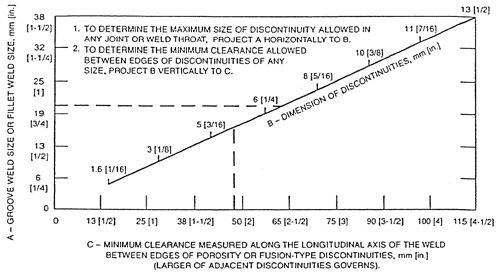
General Note: Adjacent discontinuities, spaced less than the minimum spacing required, shall be measured as one length equal to the sum of the total length of the discontinuities plus the length of the space between them and evaluated as a single discontinuity.
Figure 2
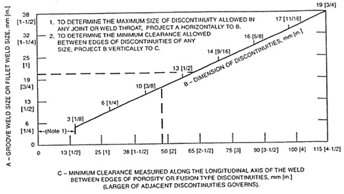
Note:
Figure 3
Weld Quality Requirements for Tension in Cyclically Loaded Structures
(This Annex is a part of AWS D1.1/D1.1M:2002 Structural Welding Code—Steel, and includes mandatory requirements for use with this standard)
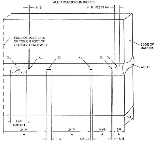
General Notes:
A—minimum clearance allowed between edges of porosity or fusion-type discontinuities 1/16 in. or larger. Larger of adjacent discontinuities governs.
X1—largest allowable porosity or fusion-type discontinuity for 3/4 in. joint thickness (see Figure 6.4).
X2, X3, X4—porosity or fusion-type discontinuity 1/16 in. or larger, but less than maximum allowable for 3/4 in. joint thickness.
X5, X6—porosity or fusion-type discontinuity less than 1/16 in.
Porosity or fusion-type discontinuity X4 shall not be acceptable because it is within the minimum clearance allowed between edges of such discontinuities (see 6.12.2.1 and Figure 6.4). Remainder of weld shall be acceptable.
Discontinuity size indicated is assumed to be its greatest dimension.
MAYES
TESTING ENGINEERS, INC.
NONDESTRUCTIVE EXAMINATION REPORT
917 - 134th St. S.W., Suite A-1 - Everett, WA 98204 - (425) 742-9360 FAX (425) 745-1737
| Michael J. Mayes, P.E. | |
| Welding Consultant | |
|
Education M.S. Welding Engineering, 1986, Ohio State University, OH Major Emphasis: Non-destructive Evaluation (NDE), Fracture Mechanics, Metallurgy and Welding Design B.S. Civil Engineering, 1980, Michigan State University, MI Major Emphasis: Structures and Material Science Registrations/Certifications
|
Summary Mr. Mayes has over 25 years of experience in materials testing. Mayes is recognized as an expert in welding, structural steel and nondestructive testing. He has been involved with numerous complex buildings and bridges in Washington, Oregon and Alaska. Mayes is active on several AWS D1 Code committees including the D1 Main Committee, Subcommittee 6 on Strengthening and Repair, Subcommittee 9 on Reinforcing Steel Welding and Subcommittee 12 on Seismic Welding. He is also a consultant to the Washington State DOT and Alaska DOT/PF for welding engineering and materials testing. Professional Societies and Affiliations American Welding Society (AWS) Publications Ten technical journal publications Experience July 1991 to Present, Mayes Testing Engineers, Inc.,Everett, WA, President Dec 1987 to 1990 - Senior Division Manager of PSI Western Washington, Professional Service Industries, Pittsburgh Testing Laboratory Division, Seattle, WA Aug 1986 to Nov 1987 - Senior Engineer, Bechtel National, Inc. Materials and Quality Services, San Francisco, CA Sept 1984 to June 1986 - Graduate Research Assistant, OSU Welding Engineering Department, NDE Group, Columbus, OH Aug 1980 to Sept 1984 - Branch Manager of Nondestructive Evaluation, Professional Service Industries, Michigan Testing Engineers Division, Detroit, MI |
| Michael Virgilio | |
| Structural Steel/NDE Manager | |
|
Education Non Destructive Testing, US Navy, San Diego, CA Welding, Pipefitting and Layout, HT A School, Philadelphia, PA Construction Management, Edmonds Community College, Edmonds, WA Welding of Non-Ferrous Metals, Everett Community College, Everett, WA Metallurgy for Non-Engineers, American Society of Metals Seminar Registrations/Certifications
|
Summary Mr. Virgilio has 13 years of inspection experience. He is an AWS Certified Weld Inspector and holds WABO and ICBO licenses for Structural Steel. Mr. Virgilio is also ASNT Level II for Ultrasonic Testing and Magnetic Particle Testing. He has extensive experience working on complex steel systems and teaches in house MTE Welding and Non Destructive Testing classes. Experience 1996 to present - Senior Inspector, Mayes Testing Engineers, Inc.,Everett, WA 1996 - Certified Weld Inspector, CMTS, Mukilteo, WA 1994 to 1996 - Certified Weld Inspector, Morse Construction 1994- Certified Weld Inspector, T.I.C., Anacortes, WA 1991 to 1994 - Certified Weld Inspector and Lead Radiographer, MMP Quality Inspections, Bellingham, WA Recent Projects Lincoln Square, Bellevue, WA Snohomish County Campus, Everett, WA Museum of Flight Addition, Seattle, WA Immunex Headquarters, Seattle, WA Seahawks Football Stadium, Seattle, WA Boeing Everett Seismic Upgrade, Everett, WA Pacific Place, Seattle, WA Safeco Field Baseball Stadium, Seattle, WA Boeing Renton Building 4-20 Asat Project, Renton, WA Boeing Everett Office Build Out, Everett, WA Boeing Everett Seismic Upgrade Building 40-56 & Bomark, Everett, WA Boeing Everett Overhead Crane Upgrade, Everett, WA Port Townsend Water Storage Tank, Port Townsend, WA Texaco Oil Refinery Shut Down, Anacortes, WA Sumas Cogenerator, Sumas, WA Nine Mile Natural Gas Pipeline, Anacortes, WA Arco Refinery, Blaine, WA |
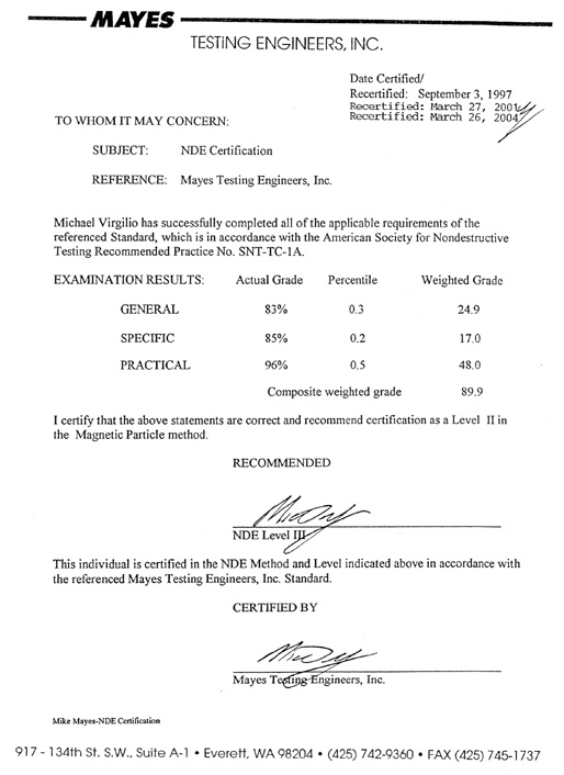
Date Certified/Recertified: September 3, 1997
Recertified: March 27, 2001
Recertified: March 26, 2004
TO WHOM IT MAY CONCERN:
SUBJECT: NDE Certification
REFERENCE: Mayes Testing Engineers, Inc.
Michael Virgilio has successfully completed all of the applicable requirements of the referenced Standard, which is in accordance with the American Society for Nondestructive Testing Recommended Practice No. SNT-TC-IA.
EXAMINATION RESULTS: |
Actual Grade |
Percentile |
Weighted Grade |
GENERAL |
83% |
0.3 |
24.9 |
SPECIFIC |
85% |
0.2 |
17.0 |
PRACTICAL |
96% |
0.5 |
48.0 |
|
Composite weighted grade |
89.9 |
|
I certify that the above statements are correct and recommend certification as a Level II in the Magnetic Particle method.
RECOMMENDED: (signed) Mike Mayes - NDE Level III
This individual is certified in the NDE Method and Level indicated above in accordance with the referenced Mayes Testing Engineers, Inc. Standard.
CERTIFIED BY: (signed) Mike Mayes - Mayes Testing Engineers, Inc.
Mike Mayes-NDE Certification
| Mark Vassallo | |
| Structural Steel/NDE Inspector | |
Education College of Oceaneering, 1987,Wilmington, CA Florida Institute of Technology, 1986, Jenson Beach, FL Lord Fairfax Community College, 1985, Middletown, VA Registrations/Certifications
|
Summary Mr. Vassallo has 17 years of inspection experience. He is an AWS Certified Weld Inspector and holds WABO and ICBO licenses for Structural Steel. Mr. Vassall is also ASNT Level II for Ultrasonic, Radiographic Testing, Liquid Penetrant Testing, and Magnetic Particle Testing. He has extensive experience working on complex steel systems and has worked on hundreds of projects in the Puget Sound area. Experience 1998 to present - Special Inspector, Mayes Testing Engineers, Inc., Everett, WA 1994 to1998 - Assistant Manager of NDE, Pacific Testing Laboratories (Division of P.S.I), Seattle, WA 1994 - NDE Coordinator, Edge Testing and Inspections, Bellingham, WA 1987 to 1994 - NDE Inspector, Quality Inspections, Bellingham, WA Recent Projects Alderwood Mall Expansion, Lynnwood, WA Boeing Everett 2004 Structural Upgrade, Everett, WA Museum of Flight, Tukwila, WA Seattle Center Opera House, Seattle, WA Everett Special Events Center, Everett, WA Amgen Headquarters, Seattle, WA Bellevue Mall Seismic Upgrade, Bellevue, WA SeaTac Airport South Terminal Expansion Project, SeaTac, WA Fred Hutchinson Cancer Treatment Center, Seattle, WA 1700 Seventh Avenue, Seattle, WA Swedish Hospital First Hill Addition, Seattle, WA Bellevue Square Corner Shops, Bellevue, WA Northgate North Shopping Center, Northgate, WA Seahawks Stadium, Seattle, WA UW Bothell Cascadia College Colocation, Bothell, WA 13th and A Street, Tacoma, WA Three Bellevue Center, Bellevue, WA Safeco Field, Seattle, WA |
EXHIBIT 1
Date Certified/
Recertified: 9-28-98
Recertified: 9-21-01
Recertified: 3-26-04
TO WHOM IT MAY CONCERN:
SUBJECT: NDE Certification
REFERENCE: Boss & Mayes Testing Engineers, Inc., Standard PQ-l Rev. 0
Mark Vasallo has successfully completed all of the applicable requirements of the referenced Standard, which is in accordance with the American Society for Nondestructive Testing Recommended Practice No. SNT-TC-1A, 1988 Edition.
EXAMINATION RESULTS: |
Actual Grade Percentile |
Weighted Grade |
|
GENERAL |
98 |
0.3 |
29.4 |
SPECIFIC |
90 |
0.2 |
18.0 |
PRACTICAL |
93 |
0.5 |
46.5 |
|
composite weighted grade |
93.9 |
|
I certify that the above statements are correct and recommend certification as a Level II in theMagnetic Particle method.
RECOMMENDED: (signed) NDE Level III
This individual is certified in the NDE Method and Level indicated abovein accordance with the referenced Boss & Mayes Testing Engineers, Inc. Standard.
CERTIFIED BY: (signed) Mayes Testing Eng., Inc.
|
414 Hewitt Road Chehalis, WA 98532 |
|
| J. M. DWIGHT | |
Experience |
1984-2005 Owner Manager We provide quality assurance testing, welding engineering and failure analysis. 1981-1984 Manager, Production Department
1978-1981 NDE Engineer and Manager of Quality Assurance
1976-1978 Supervisory Civilian Engineer -GS 12
1972-1976 Civilian Welding Engineer -GS11
1971-1972 Civilian Engineer -GS11
1968-1971 Graduate Research Assistant
1965-1967 Welding Instructor
1964-1966 Machine Shop & Welding Instructor
1957-1960 Damage Control 2nd Class (Welder)
|
Education |
1960-1964
1968-1971
|
Interests |
J. Dwight is active in the Seattle Chapter of the American Welding Society and is past chairman of the Puget Sound Section of the American Welding Society. He enjoys giving technical talks on material engineering problem solving. J.M. Dwight is an active commercial pilot and flies his own Cessna-182. |