

| << Previous | Contents | Next >> |
Pavement Utility Cuts
4. Reducing Pavement Cuts by Integrating Technology
The previous chapter discussed methods that state and local agencies can implement to control the frequency of pavement utility cuts in highways and streets. While controlling these cuts can help maintain order, ensure that the repairs are done in an orderly manner, and encourage utility companies to share resources and trenching operations, it is also desirable to decrease the number of utility cuts necessary. This chapter presents information that can help transportation agencies effect this reduction while maintaining access for all those legitimate and responsible parties that request it. This chapter also contains the results of the survey conducted for this project as they pertain to the use and perceptions of trenchless technology by various state transportation agencies.
As technology advances, the ability to perform trenchless utility installation and maintenance will also advance, allowing a progressively greater proportion of such work to be completed without trenching through the pavement structure. To this end, this chapter presents basic information about the methods, equipment, and applications available for use in trenchless utility construction, and provides insights into conditions and situations where trenchless applications would not be appropriate, thus requiring trenching operations. It should be recognized that there are many conditions where trenchless applications are not appropriate, such as emergencies, where immediate trenching of the pavement is necessary, and advanced planning simply cannot be done. In other cases, conditions such as the nature of the soils and rocks below the surface, or the presence and/or uncertain location of existing utilities preclude the use of trenchless technology.
Rather than attempt to restate and capture the large amount of information regarding this continually advancing technology, this chapter summarizes the basic aspects of the capabilities, and provides extensive references to other, more detailed, sources of information. Throughout the sections that follow, references are given where additional information can be found regarding specifics on the various trenchless technology methods, their application, relative cost, and other information. Comprehensive glossaries of terms used in this and other literature on trenchless technology can be found in references 17, 20, and other guidelines with respect to the various types of trenchless technology.
4.1 Available Technology
This section discusses some of the available trenchless technologies and how agencies, engineers, and contractors are using this technology to reduce the number of pavement cuts. The methods discussed in this section include:
- Horizontal Directional Drilling (or Guided Boring).
- Auger and Slurry Boring.
- Pipe Jacking and Microtunneling.
- Impact Moling and Ramming (or Thrust Boring).
- Pipe Bursting.
It is not the purpose of this manual to provide detailed information on all aspects of each method, but instead to provide basic information on the following topics for each, including:
- Method.
- Equipment.
- Practical Applications.
- Specifications and Guidelines.
Additional information regarding advantages and limitations, and relative cost of trenchless technology as a whole, as well as for individual methods will be discussed in section 4.2. The relative cost comparisons will be made both among the different methods and compared to trenching methods.
4.1.1 Horizontal Directional Drilling (or Guided Boring)
The original application of horizontal directional drilling (HDD) originated in oil fields in the early 1970s. It was used to access deposits of oil near, but not directly under, the drill rig. HDD was first used successively in a river crossing where a 183-m (600 ft) distance was bored using a modified rod pushing tool which had no steering capability.(17) The process was soon modified to drill pipelines under rivers, achieving individual placements of 107-cm (42-in) diameter pipe over 1220-m (4000-ft) lengths. The first use of what is called guided boring was for electrical cable installation under obstacles such as airport runways, highways and rivers.(18) The technology has been used on a limited basis for public utilities in urban and suburban locations since the late 1980s. During that decade, the Electrical Power Research Institute and the Gas Research Institute sponsored research into the installation and construction of conduits and gas pipelines.
As recently as 1995 many contractors and utility companies were reluctant to use trenchless technology due to problems (both perceived and real) with locating existing underground utilities and the accuracy and precision with which the operators and equipment worked. Utility companies, government agencies and contractors were hesitant to embrace the technology because of these potential problems, as well as the much higher cost of directional drilling.
As HDD and guided boring technology has advanced, primarily in the tolerances for vertical alignment, their applications have expanded from pressurized pipes and conduit to gravity-driven systems. In addition to the advances in technology, the cost of directional drilling has dropped significantly in the past decade. The International Society of Trenchless Technology estimates that the relative cost of HDD has fallen below that of traditional trenching for many applications.(18) Horizontal directional drilling has been used on large, high-profile projects such as airports, ship channels, rivers, and others.
Methods
Horizontal directional drilling is generally divided into three classifications based on the typical application, and technical parameters including pipe diameter, depth of bore and bore length. The three classifications are mini-, midi-, and maxi-HDD, corresponding to small, medium and large diameter installation.(17) Table 11 provides typical technical data for the three classifications. A complete description of HDD procedures and methods is given in Horizontal Directional Drilling - Good Practices Guidelines, by the HDD Consortium.(19)
The HDD process typically consists of two stages: boring an initial pilot hole along the proposed alignment, and subsequently enlarging the hole to the diameter of the pipe.(17) Figure 1 and figure 2 illustrate the two stages of this process. The first stage is to drill the pilot hole, which is generally of a small diameter. The process begins with a small, portable boring rig set up near the point of entry to which a hollow drill string with a cutting head is attached. The rig pushes the cutting head into the ground at a shallow angle. When a change of direction is required, the rotation of the cutting head is stopped, and the drilling action on a single side creates an eccentricity which steers the head in the appropriate direction. The direction of the bore and the location of the cutting head is monitored by a beacon (or sonde) mounted in the drill head, which emits a signal that is received at the surface. In this way, the depth, direction, and other parameters of the boring process can be monitored and modified throughout the operation. Once the pilot bore exits at the appropriate location, as indicated in figure 1 as Reception Pit, the backreaming device and pipe product are fitted to the drill string and pulled back to the original entry location, shown in figure 2. This is accomplished by a rotating reamer and pipe.
| System Description | Product Pipe Diameter | Depth Range | Bore Length | Torque | Thrust / Pullback | Machine Weight (including truck) | Typical Application |
|---|---|---|---|---|---|---|---|
| Maxi-HDD | 600-1200 mm (24-48 in) | £ 61 m (200 ft) | £ 1500 m (5,000 ft) | £ 108.5 kN-m (80,000 ft-lb) | £ 445 kN (100,000 lb) | £ 267 kN (30 ton) | River, Highway Crossing |
| Midi-HDD | 250-600 mm (10-24 in) | £ 23 m (75 ft) | £ 274 m (900 ft) | 1-9.5 kN-m (900-7,000 ft-lb) | 89-445 kN (20,000 - 100,000 lb) | £ 160 kN (18 ton) | Under rivers and roadways |
| Mini-HDD | 50-250 mm (2-10 in) | £ 4.5 m (15 ft) | £ 183 m (600 ft) | £ 1.3 kN-m (950 ft-lb) | £ 89 kN (20,000 lb) | £ 80 (9 ton) | Telecom and Power cables, water and gas lines |
This drilling process is relatively quick, and there is minimal disruption around the launch area, service connections, and reception pits. There is always a danger of striking existing utilities, and power lines in particular, so it is important to use strike-protection equipment.(18) In addition to such protection, a subsurface utility engineering (SUE) study should be completed prior to construction. This type of study is discussed in section 4.3 of this report.
Figure 1. Drilling the Pilot Bore.(20)
Figure 2. Backreaming and Pulling the Pipe.(20)
Several types of HDD methods are in use today. These include fluid-assisted mechanical drilling, high-pressure fluid jetting, and dry boring.
Fluid-Assisted Mechanical Drilling
Fluid-assisted mechanical drilling utilizes mechanical drill bits with an angled head. In order to make a straight bore, the entire shaft and drill head is rotated, thus providing alternating eccentric pressure on all sides of the bore hole. Steering is achieved by ceasing the rotation of the drill head, which concentrates the eccentric force to one side. Thus, a curved path can be bored through the soil. The mechanical drill bits commonly used include slim cutting heads with slanted faces for short or small diameter bores, and diamond-mounted roller/cutters with mud motors for long or large diameter bores. A mixture of bentonite and water is normally used for the drilling fluid, sometimes called mud. This fluid carries the spoils in suspension, and can be filtered and reused with a recirculation system. The mud also stabilizes the bore hole during backreaming.
High-Pressure Fluid Jetting
This type of HDD uses high-pressure fluids to erode the bore hole rather than drill it with a cutting head. In most cases, the fluid used is a bentonite-water mix or some other polymer-based slurry in order to stabilize the bore hole and prevent its collapse.(17) Steering is effected by offset jets and other steering devices in the system. The energy of the high-pressure fluid dissipates quickly after the fluid exits the jets and after eroding a small amount of soil, thus problems of soil overcutting and damage to existing utilities are unlikely.(17)
Dry Boring
Dry boring is rarely used, except in instances where mini-HDD systems utilize compressed air in hard, dry soils and calcified or soft rock formations.(17)
To ensure the correct cutting head or method is used, a series of ground investigations must be conducted prior to construction. Clay and other cohesive materials are best suited for HDD operations. Other materials that are less cohesive but consist of smaller particles that can remain in the drilling fluid suspension for an adequate time can also be used with HDD methods. If the investigation reveals granular soils and gravels, then HDD generally should not be used. With such material, there is a greater potential for a collapse of the bore hole during both the pilot drilling and back reaming, and steering accuracy may not be adequate. However, according to Iseley and Gokhale, today's technology enables large drilling operations to be conducted in soil formations consisting of up to 50 percent gravel.(17)
Equipment
There are two major types of HDD rigs: surface-launched and pit-launched. Figure 3 shows a typical surface-launched HDD rig. Each type has its advantages and disadvantages. Surface-launched machines do not require entry and exit pits, although some type of excavation is normally required to make the pipe connections below the surface. Surface-launched machines generally use somewhat flexible pipe since at least two curves are made (surface entry to horizontal and horizontal to exit at the surface). The pipe segments can be relatively long, and thus the cost of extra connections is reduced.
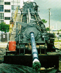
Figure 3. Surface-Launched HDD Rig (Courtesy of Purdue University).
Pit-launched machines are lowered into an excavated pit large enough for the machine and the pipe segments. Often, this restricts the length of the pipe segments, and the additional pipe connections can add cost to the project. Pit-launched operations are often suited for restricted spaces, and can be used in areas where horizontal space or ROW is limited. This type of HDD machine is generally intended for straight bores, and often uses much stiffer pipe than the surface-launched pipes. This can significantly limit the ability to steer around obstacles.
There are many different equipment manufacturers that produce variations on the standard HDD equipment. Typical equipment used in a basic HDD drill head includes, as shown in figure 4.(21)
- Drill bit.
- Fluid nozzle.
- Beacon housing.
- Beacon.
- Beacon housing plug.
- End cap.
- Screen sub plug.
- Screen.
- Screen sub.
- First segment of drill pipe.
Figure 4. General HDD Drill Head Assembly.(21)
Other components not shown in figure 4, but that are required in most HDD operations, include:
- Drilling frame.
- Rods and drill shoes.
- Mud motor.
- Percussive drilling assembly.
- Reamers and pullback attachments.
- Tracking instrumentation.
- Hydraulic controls and gauges.
- Cable or pipe pulling devices (see figure 5).
- Drilling fluid delivery, filtering, recirculation, and containment.
- Power source.
- Transport trailer.
Figure 5. Towing Heads for Directional Drilling Applications.(20)
Another important component that is not part of the actual HDD operation itself, but is indispensable, is bore tracking equipment. This equipment receives the signal sent by the beacon indicated by Item 4 in figure 4. In order for the tracking equipment to perform properly, it must be free from both active and passive interference. Active interference could be magnetic fields and radio frequencies, while passive interference may originate from adjacent structures, buried metals, salts, etc. A walkover tracking system employs a handheld receiver and an operator who "walks over" the drill head, monitoring its progress and steering it in the appropriate direction. Non-walkover systems are used where the depth of the drill head exceeds the range of a walkover system. In such cases, a steering tool and survey probe within the drill head must be used to navigate the bore through the underground soil.
Practical Applications
As shown in table 11, HDD can be used in a wide range of applications, from 50 - 1200 mm (2 - 48 in) in diameter, and for bore lengths of up to 1500 m (5000 ft), depending on the pipe size. HDD applications can also be used at depths up to 61 m (200 ft), again depending on pipe size. HDD applications are used to install cable, conduit, gas, and water pipes under roadways, railways, rivers, lakes, and environmentally sensitive areas. A typical installation rate is about 100 m/day (328 ft/day) using a skilled crew.(17) The latest equipment is reported to allow installation of gravity pipelines demanding close tolerances in vertical alignment.(18) A comprehensive troubleshooting table listing potential problems, probable causes, and possible solutions can be found in reference 17.
Specifications and Guidelines
Several states and cities have developed standards for HDD applications. The state highway agencies of California, Florida, Indiana, Michigan, Minnesota, New York, Oregon and others have developed variations on HDD specifications.(17) A sample specification from the Florida Department of Transportation is included in Appendix C. The City of Los Angeles, California has also developed specifications for HDD applications, which is also included in Appendix C. In addition to specifying the fluid, accuracy and precision of the drill head, turning radius, and limiting surface subsidence and distortion, such specifications should address at least the following, from reference 17:
- Nature and extent of subsurface exploration.
- Procedures for approving alternate drilling fluids such as polymers.
- Minimum depth of cover.
- Qualifications of contractors and crews.
- Contingency planning in the event of roadway surface disturbance, including subsidence or upheaval, a drill bit breaking the surface, or drill fluid escaping to the surface.
- Backfilling requirements for abandoned, off-target pilot holes.
Many state highway agencies specify the types of pipe to be used, the method of construction, methods of quality control and testing, location and tracking, and documentation requirements for HDD. As the technology becomes more widespread, as expected both by state highway agencies as well as the HDD industry, the agencies will be required to place more controls on the methods and uses of the technology in order to maintain the integrity of the existing utility and pavement infrastructure.
4.1.2 Boring
Two types of boring methods are most commonly used: auger boring and slurry boring. Both methods have been in use to install steel pipe encasements beneath roadways since the 1940s. These systems are commonly un-steered, and thus their course may be altered by unexpected objects such as large boulders or other obstacles. Slurry boring is quickly being replaced by the HDD methods, due to their similarities, and HDD's location and guidance capabilities.
Methods
The auger boring method forms a horizontal bore hole through the ground using a cutting head attached to a helically-wound auger flight. The auger rotates the cutting head and removes the excavated soil from the bore by the rotation of the auger. The auger flight is typically contained in steel casing, since it must resist the action of the auger. Most auger boring systems are equipped with pipe-jacking machines to move the casing forward as the cutting head advances. This ensures stability in the hole. The product pipe is inserted into the casing once it has been installed.(18) If the casing pipe is not jacked along with the auger head, the pipe diameter should be small, or the soil conditions should adequately support an unstabilized hole. The hole is typically bored straight through the underground material from an entry pit to a reception pit. In some machines, vertical directional control is possible, but horizontal directional control is not generally used. A diagram of a typical auger boring setup is shown in figure 6.
To setup and operate the auger boring machine, the following steps need to be performed:
- Construct the shaft with adequate foundation and thrust block.
- Place the tracks on the foundation.
- Place the auger boring machine on the tracks.
- Place the casing with the auger inside, between the front of the shaft and the machine.
- Install the cutting head.
- Attach the auger and casing to the machine.(17)
Figure 6. Typical Auger Boring Operation.(17)
Slurry boring utilizes a cutting head and drilling fluid, similar to that used in HDD, to assist in the boring process and to aid in removal of the spoils. This type of boring generally is not steered, but beacons or sondes are often used to locate the boring head. Slurry boring is sometimes called wet boring or fluid-assisted mechanical drilling. Slurry boring differs from HDD in that there are lower fluid pressures and higher flows. Slurry boring does not only rely on fluid for cutting; the hole is also cut mechanically. The drilling fluid used can be water, a bentonite slurry, or a polymer slurry. As with HDD, the bore is cut in a two-stage process. The first is the installation of a pilot hole, followed by the cutting of the bore hole along the pilot alignment which will accept the casing pipe. Iseley and Gokhale provide more details about the process.(17)
- Construct the drive and reception shafts.
- Drill the pilot hole.
- Check accuracy of the pilot hole.
- Ream the hole to the bore hole diameter.
- Insert the casing in the bore hole.
- Grout between the casing and the bore hole.
- Insert the desired carrier pipe.
- Construct the casing / carrier pipe bulkheads.
- Backfill and restore the shaft areas.
After the setup process, the following procedure is typical, again from reference 17: - Excavate the material ejected through the shaft.
- Install the first casing.
- Disconnect the casing and auger, and move the machine to the back of the pit.
- Place the next casing and auger, and connect it to the previous casing.
- Repeat the process until installation is complete.
Equipment
There are two types of auger boring equipment: track- and cradle-type. The components required for a track-type system include the track system, boring machine, casing pipe, drilling / cutting head, and the auger. Additional equipment could include a casing lubrication system, a cutting head locating system, and a casing leading-edge band. A track-type setup is shown in figure 7. The casing is advanced by hydraulic jacks in a continuous motion, simultaneously with soil excavation, spoil removal, and casing installation. A stable foundation and adequate thrust block are necessary. The tracks must be in line with, and on the same grade as the bore hole. Accuracy can be affected if the track settles, which could cause binding forces in the bore hole. If the base of the entry pit can support the boring machine and other component of the system adequately, the tracks can be set upon the base of the pit, or on a bed of crushed stone or even portland cement concrete for support. The thrust block distributes jacking forces over a sufficient area so that the soil behind the block is not disturbed. If the thrust block moves in any direction, accuracy of the bore hole could be compromised.
The cradle-type method is not used as extensively as the track-mounted system. The machine and casing system are suspended by a crane, as shown in figure 8. This type of equipment is generally used for gas and oil pipeline construction.(17) The equipment necessary for the cradle-type system is almost identical to the track-mounted system, without the tracks, and with the addition of a crane and a frame capable of lifting the entire boring machine and casing system. The cable, winch and jacking lug provide the propulsion needed to drive the head and casing through the ground.
Figure 7. Track-Type Auger Boring Operation (Courtesy of Purdue University).
Figure 8. Cradle-Type Auger Boring System.(17)
The second method of boring is slurry boring, and is associated with non-tracking and non-steering operations. Slurry boring equipment is either surface or pit launched. Similar to auger boring, the drill tubing is rotated and pushed forward, while a drill bit mechanically cuts the bore hole. The drilling fluid is introduced in to the drilling tube using a water swivel tee. As shown in table 12, the typical diameter hole is between 51 and 305 mm (2 and 12 in). Most times, slurry boring involves an uncased bore hole, making it suitable for small diameter applications in stable ground. With proper installation, only minor subsidence will occur. Because of the use of water, the operator does not have control of the excavation volume. An experienced operator is needed in the event of unexpected situations.
Table 12 provides technical information about these two major methods of boring. The vertical and horizontal accuracy listed in the table for auger boring can be maintained using a grade-controlled steering system. Without the steering head, accuracy depends on groundwater conditions, drive length, initial setup and operator skill. It should be noted, however, that the data in table 12 was recorded in 1997, and further advancements in the technology have been made. For example, some boring contractors have reported performing slurry bores up to 2.5 m (96 in) in diameter.(22)
| System Description | Bore Length | Diameter | Drive Shaft Length | Vertical Accuracy | Horizontal Accuracy |
|---|---|---|---|---|---|
| Auger Bore | £ 270 m (890 ft) | 100-1500 mm (4-60 in) | 9.1-10.7 m (30-35 ft) | ± 13 mm (0.5 in) | 1% of bore length |
| Slurry Bore | 15-100 m (50-328 ft) | 50-300 mm (2-12 in) | 4.5-6.1 m (15-20 ft) | < 2% of bore length | < 2% of bore length |
Practical Applications
Auger boring may be used in almost all applications where curves and horizontal alignment do not present a great issue. It is especially suited for large-diameter bores such as water and wastewater applications, where precise adherence to grade is important. Auger boring can be used in most soil conditions, including wet sand, dry clay, and solid rock. It is best suited for cohesive soils or stable, non-cohesive soils. When selecting the auger boring equipment, ground subsidence and soil heave should be considered. Subsidence is the most common problem, caused by over-excavation when the bore hole is too large or when soil enters the end of the casing pipe.(17) An experienced operator can feel, or detect the changing ground conditions and take corrective actions.
The construction rate for auger boring can range from 1 to 12 m/hr (3 to 40 ft/hr) depending on the soil conditions.(17) This does not include construction of the entry and exit shafts. If the excavation embankments can be sloped, and are less than 3 m (10 ft), shaft construction can take a single day. However, if the sides cannot be sloped, or are too deep, a steel sheet piling support system may be required, which could take several weeks. The size of the required work space is typically determined by the bore hole diameter and length of casing segments. A common shaft size is 9.1 - 10.7 m (30 - 35 ft) in length by 2.5 - 3.6 m (8 - 12 ft) in width.(17)
Slurry boring is not used as often as it has been in the past, due to the popularity and improved technology of horizontal directional drilling. It is used by many contractors, however, and can be used successfully over a wide range of utility applications and ground conditions. Slurry boring is best suited for firm, stable, cohesive soil conditions, but can be used in wet, non-cohesive soils if extra precautions are taken. The National Utility Contractor's Association publication Trenchless Construction Methods and Soil Compatibility Manual contains information about safety precautions for construction under various soil conditions.(23)
Specifications and Guidelines
Since auger boring has been in use for so many years, all state highway agencies allow its use, although many do not have specifications governing its application.(17) In cases where state specifications exist for auger boring, they are often general in nature, require the use of steel casings, only describe the type of pipe material that can be used, and limit the damage allowed to surrounding pavements, structures, or other features.(17) A sample of a boring specification is included in Appendix C.
Slurry boring is less popular among the state highway agencies. Many do not allow this type of boring, since it is similar to water jetting, in that overexcavation can occur and subsidence can result. Slurry boring is used extensively in Texas, Louisiana, Mississippi and Oklahoma.(17)
4.1.3 Pipe Jacking and Microtunneling
Pipe jacking (PJ) and microtunneling (MT) are very similar. In fact, in North America, microtunneling has become the preferred terminology for all remote-controlled pipe jacking operations. Traditionally, the term microtunneling has been limited to those operations with diameters up to 914 mm (36 in), although in the US the term has been applied to all diameters of this method. Operations greater than 914 mm (36 in) in diameter, where a worker can enter the pipe, has been traditionally called pipe jacking.(24) Generally, pipe jacking operations require a person to be in the pipe, while microtunneling does not. Microtunneling was developed in 1975 in Japan, and was introduced into the United States in 1984, on a project in Miami, Florida.
Initially, this method of trenchless technology was thought to be ill-suited for use in the US, due to highly variable geology and expense. In 1987, however, the City of Houston began using the technology extensively to expand their sewer system. In four years, over 21 km (13 mi) of microtunnels and 18 km (11 mi) of jacked pipe were installed in Houston. By the end of the sewer construction process, the City of Houston had developed a good specification for microtunneling, which was modeled after the US Military Unified Facilities Guide Specifications. This can be found in the sample specifications section in Appendix C, as can a sample from the City of Wichita, Kansas.
Methods
Both PJ and MT methods require launch pits and reception pits. For long, man-entry operations, intermediate jacking stations can be used to extend the drive length, which is based on the jacking capacity of the machinery. In non-man-entry operations, the jacking length is limited to the jacking capacity at the entry pit, and only one drive can be completed for each pit. table 13 provides information regarding typical applications, pipe materials, and pipe length and diameters available for use in PJ or MT operations.
In the larger diameter, pipe jacking operations, the tunneling is either done by hand, or by mechanical means such as backacter, cutter boom, or rotating cutter head (see figure 9). As the material is removed through the tunnel, by means of a bucket on rails, conveyor belt, or vacuum system, the pipe is jacked into place, which advances the tunneling operation forward.
| System Description | Product Pipe Diameter | Bore Length | Pipe Material | Typical Applications |
|---|---|---|---|---|
| Pipe Jacking | > 900 mm (36 in) | £ 1000 m (3,280 ft) | Concrete, steel, fiberglass, clay | Crossings, sewers, force mains |
| Microtunneling | 450-1500 mm (18-60 in) | £ 460 m (1500 ft) | Concrete, steel, fiberglass, clay | Crossings, sewers, force mains |
In order to minimize friction between the pipe string and the ground through which the pipe is traveling, lubrication is often used. In the early days, the problem of friction was overcome by brute force - using larger jacking frames to force the pipe through the ground. This often led to pipe failures, when the jacking frame exceeded the axial capacity of the pipe.(18) Lubrication systems using bentonite slurry were introduced which not only lubricates the pipe as it moves through the soil, but fills voids left by the tunneling process. Jacking forces have been reported to decrease by 20 - 50 percent, with the most common reduction being about 20 - 30 percent.(17) It is often important to keep the pipe string moving through the ground to reduce the effect of the soil "gripping" a pipe string which remains stationary too long.(18)
The basic procedure for pipe jacking, as reported in reference 17 , is as follows:
- Place jacking equipment in the drive shaft.
- Place PJ track in shaft and adjust to the proposed design line and grade.
- Install laser guidance system.
- Place shield or tunnel boring machine (TBM) on the jacking tracks.
- Mate jacking push plate to shield or TBM.
- Advance shield or TBM through the prepared opening in the forward shaft support structure. Begin the excavation and spoil removal process.
- Continue excavation, spoil removal, and forward advancement until shield or TBM is installed.
- Retract jacks and push plate.
- Place first pipe segment on the jacking tracks.
- Mate push plate to pipe and pipe to the shield or TBM.
- Initiate forward advancement, excavation, and spoil removal.
- Repeat pipe jacking cycles until complete line is installed.
- Remove shield or TBM from reception shaft.
- Remove jacking equipment and tracks from drive shaft.
- Restore site as required.
Regarding the pipe size and length shown in table 13, reference 17 reports that the minimum recommended pipe diameter for pipe jacking operations is 1075 mm (42 in.) and that there is no theoretical upper limit, but that the largest diameter is usually approximately 3.7 m (12 ft). It further reports that the most common sizes fall within 1220 mm (48 in.) to 1830 mm (72 in.) in diameter.
In microtunneling, the remote-controlled tunneling device excavates the bore into which the product pipe is installed. This method is generally too small in diameter to allow a man to enter the pipe. The cutting head may be fitted with blades for soft soils, picks for hard soils / soft rock, and disc cutters for hard rock. The spoils can be removed from the bore using a mechanical auger, vacuum, or slurry. A flight of augers running through the newly installed pipe is preferred for short drives, due to the faster removal rate compared to other systems.
Using the slurry removal system, water or bentonite may be used to convert the soil into a slurry at the cutting face. The slurry, which is water based, is then pumped to the surface along pipes within the product pipeline. The spoil is then collected in a processing plant, where it is removed and the slurry recycled back to the cutting face. The slurry system can be used to control external groundwater by balancing the slurry pressure so that it offsets the groundwater pressure. The slurry system is usually more suitable for long drive lengths, especially in granular soil and where there is groundwater.
Ground conditions have a large impact on the choice of microtunneling system for a particular situation as they will determine the type of machine to be used, the cutting head, the spoil removal system and the jacking force required.
Microtunneling machines can be steered to ensure the correct line and level of the product pipe. The accuracy of the bore is normally determined using laser guidance control systems. The machines are operated from a control cabin at the surface.
Equipment
Various types of equipment are used in pipe jacking and microtunneling operations. Figure 9 shows the various types of pipe jacking shields that can be used, depending on the tunneling method. The jacking shield protects any workers at the end of the pipe string in the event of a tunnel collapse. As the shield advances underground, additional pipes are added to the pipe string at the drive shaft.
For long lengths of pipe, intermediate jacking stations may be necessary to allow sequential thrusting of sections of the pipeline. Drives of several hundred meters are attainable using this technique. These pipes are specially designed to ensure that all joints are flush within the pipe wall, and that they are strong enough to withstand the jacking forced applied to them.
Figure 10 shows the equipment and setup for a typical pipe jacking operation. Notice the operator at the entry to the pipe in the pit. Figure 11 shows the same type of setup for a typical microtunneling operation. In this operation, the operator is above the ground, in a control station. The pipe diameter is too small for the operator to enter, and the entire process must be done by remote control.
Figure 9. Various Pipe Jacking Excavation Techniques.(17)
Figure 10. Pipe Jacking Setup.(17)
Figure 11. Typical Microtunneling Setup.(17)
Practical Applications
Favorable soil conditions for pipe jacking is a sandy clay, although many other types of soil conditions can be accommodated if appropriate precautions are taken.(17) Microtunneling favors wet sand for the slurry system, and sandy clay conditions for the auger system.(17) It can be used in many types of rock as well, with the proper equipment. Microtunneling is also well-suited for marine and other water crossings.
Types of casings are generally limited to steel, reinforced concrete, and other materials that can transmit the jacking and other forces involved in the pipe installation. The microtunneling method generally produces lower jacking forces, and thus other materials have been used, such as vitrified clay, ductile iron, and polyvinyl chloride (PVC).(17)
Under good working and soil conditions, a microtunneling crew can average 9 m to 18 m (30 to 60 ft) in a standard shift.(17) This production rate varies depending on the soil conditions, jacking forces required, and skill of the crew, among others.
Specifications and Guidelines
Pipe jacking and microtunneling is allowed and specified by many state highway agencies and cities throughout the United States as well as the US Department of Defense. Some examples of agencies with defined specifications are the State of California, the Cities of Los Angeles, California, Wichita, Kansas, Houston, Texas, and the Dallas-Fort Worth International Airport. Sample specifications are provided in Appendix C, including an excellent sample from the Florida DOT.
4.1.4 Impact Moling and Ramming
Impact moling and pipe ramming may be the most widely used trenchless installation methods. Tens of thousands of impact moles are in service with utilities and contractors worldwide. They first appeared in Russia and Poland in the 1960s. These methods offer solutions to a wide range of installation problems, particularly over short distances.(20) The impact mole and pipe ramming methods use the same type of equipment, but they employ different techniques.
Impact moles are commonly used to install gas and water lines and cabling. The impact mole produces a bore by displacing soil using a hammering, or percussion, action. It is a type of soil compaction technique, where the soil is displaced radially from the center of the bore and not removed. This earth piercing tool, as it is known in North America, is a self-propelled down-hole hammering device that is used for the placement of small diameter pipes, ducts and cables.(20)
Pipe ramming is a non-steerable technique for pipeline installation. Typically, an open-ended steel casing or new pipe is driven through the ground by a percussive hammer from a drive pit. This technique is typically used under railways, road embankments and waterways. Pipe ramming installation distances are relatively short, about 50 m (164 ft) on average.(20) Since this technique usually involves pushing a open-ended pipe, after is has been rammed to the other end of the drive, the pipe or casing remains filled with soil. This must be removed by various methods that will be discussed within this section.
Methods
Although these two types use similar methods to drive a pipe or pull a conduit through the ground, some aspects of their operations can be quite different. For this reason, the methods section will be divided into two segments.
Impact Moling
Figure 12 and figure 13 show the common method of the impact moling operation. The mole device is propelled through the soil and can pull a new pipe behind it, depending on the application. The bore hole is formed by the displacement of soil using a compacting device called a mole that is generally shaped like a torpedo.
Figure 12. Typical Impact Moling Operation.(20)
The mole is composed of a long hollow cylindrical housing with a conical-shaped displacement head at the front and a percussive piston inside. It is forced through the soil by applying a static thrust force or a dynamic impact energy, most commonly powered by compressed air.(18) The surrounding soil grips the mole and prevents its backwards movement. The performance of the mole depends on the soil type and ground conditions in which it is operating. The percussive action of the impact mole compacts and displaces the soil in the immediate area surrounding the formed bore. No spoil removal is needed. The impact mole also has a self-propelled feature, and reverse capacity, so it can be withdrawn if it has deviated from the desired path.(17) The bore may always take the path of least resistance in nonhomogeneous soils, and this must be considered in the project planning phase. Piercing tools can penetrate even the most adverse soil types, but solid rock is unsuitable for this technique.
Figure 13. Impact Moling Process.(17)
In impact moling, two pits are excavated, one to launch the mole and the other to receive it. A launching cradle is set up and adjusted to set the line and level of the mole before the operation commences. This ensures that the mole will reach the reception pit and will emerge at the correct depth. The launching pit is typically 1.5 m (5 ft) long and 1m (3.3 ft) wide by 1m (3.3 ft) deep. The reception pit should be at least the length of the mole to allow its removal. After the hammering tool has constructed the bore hole, the product pipe can be installed by pulling or jacking. As mentioned, it can also be installed while the bore hole is being molded.(20) This is advantageous for loose soils where an unsupported hole is susceptible to collapsing. The bore hole diameter is limited to the size of the piercing tool's cylindrical housing.
This method is typically not steerable, but steerable systems have recently become available. The steerable impact moles allow for curved trajectories and bores with multiple direction changes and alignment corrections during the moling process.(26) To ensure successful installation with the non-steerable impact moles, it is important that the direction, depth and level are accurately established before the mole is launched. Monitoring equipment can be used to track the progress of the mole through the ground. If the mole meets an obstruction or is seen to deviate from its course, it can be withdrawn and work restarted. It is also essential that no pipes, ducts, or cables lie along the intended route of the new pipeline. They can potentially damage the mole, or be damaged by it. However, it is possible for impact moles to deal with some obstructions without being deflected off course by attaching a different head type that allows for different ground conditions.
Pipe Ramming
The pipe ramming operation requires the establishment of a solid base on the launch side of the installation pit, shown in figure 14. Normally, a concrete mat is used against the side of a slope or in a start pit.(20) Guide rails are installed on the mat, and the first length of steel casing is placed on them. The cutting edge of the pipe is formed by welding a steel band to its exterior surface and the ramming hammer is attached to the rear of the pipe. Depending on the diameter of the casing and the impact hammer, inserts can be used to ensure solid contact between the hammer and the pipe.(17)
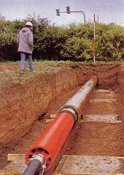
Figure 14. Pipe Ramming Entry Pit.(20)
Pipe ramming can be thought of as an extension of impact moling. The ramming hammer forces the pipe into the ground along the line of the guide rails. It is in essence a large impact mole that fits into the end of the steel casing. Steel is used since the pipe must be strong enough to withstand the impact forces created by the hammer. The wall thickness is also important in the design. Once one pipe segment has been driven, the hammer is stopped and moved. The next length of casing is welded in place. It may be necessary to lubricate the outer surface of the casing. This cycle is repeated until the leading edge of the first pipe arrives at the reception shaft.(20) Since pipe ramming is an unguided process, it is important that the initial set-up be accurate in line and grade. Gravity draws the pipe down, so initially the ramming should begin on the upstream side of the crossing.(17)
Compressed air or water is used to remove the soil from the casing. For large casings, an auger can be used. If the soil conditions are appropriate, a closed casing can be used. Continuous casing support is provided to the bore hole at all time, thereby preventing over excavation. Also, no water is needed in the excavation. After installation, the casing can be used as a pipe, or as a duct for most types of pipe or cable.(20)
To install a pipe, the following procedure is used on a typical ramming operation:(17)
- Construct an adequate launch shaft.
- Install a cone or band on the leading edge of the casing.
- Place the casing in the drive shaft and adjust for the desired line and grade.
- Attach the hammer device and connect it to a pneumatic or hydraulic power source.
- Initiate the drive and continue until installation is complete. For multiple pipe segments, remove the hammer, weld another pipe to the end of the casing, and repeat the cycle until installation is complete.
- Remove the cone or band (if used) and clean out the casing.
- Remove the equipment.
- Restore the area as required.
Equipment
The non steerable moles are designed with either fixed or moving heads. The fixed-type hammer, operated by compressed air, impacts on a solid head that is welded or screwed onto the body of the tool. The moving-head hammer impacts on an intermediate anvil and the head that penetrates the ground is mounted on a spring. In theory, the moving-head hammer allows all the initial impact energy to concentrate on pushing the head into the ground, whereas the fixed-type head must overcome friction on the housing and move the body forward at the same time.(26)
There are two basic head shapes: a cone (or stepped) and chisel head. The cone pierces the ground and pushes the soil aside. The stepped head also acts like a cone when the steps fill with soil, but when the head strikes an obstacle, the stepped edges concentrate the impact energy against the obstruction. This may apply sufficient force to move or shatter the obstruction. A smooth cone would tend to be deflected by the obstacle.(20) An example of a stepped cone head is shown in figure 15.
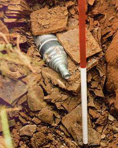
Figure 15. Stepped Cone Impact Moling Head Emerging at the Reception Pit.(20)
The non-steerable bores are intended to advance in a straight line. The operator can maintain alignment only through the tool's air supply. Accuracy of the mole is influenced by its speed. The average rate of advance is 0.3 to 1.5 m/min (1 to 5 ft/min) for a non-steerable mole, depending on the displacement head configuration and soil conditions.(26) When selecting the head configuration, it is necessary to balance the desired advancing speed and boring stability. Soft soils cause the head to lose traction and its speed has to be reduced. The forward motion is increased with the application of additional static pressure. Impact moles can be used accurately in most compactable soils for distances up to 10 m (32 ft). For greater distances, where accuracy is reduced, the practice of stitching can be employed. Small pits are excavated along the mole's route so that line and level can be verified. Moles are generally used to install small diameter service pipes of between 30-80 mm (1-3 in) in a single operation. Multiple passes of the mole can achieve diameters between 200 and 500 mm (8-10 in). Product pipe is commonly PVC, high density polyethylene (HDPE) or steel.(26)
For pipe ramming, either an open-ended or closed-ended pipe can be rammed. For closed-ended pipes, the face must be cone-shaped, similar to the impact moling head. The ram compresses the soil as the casing is rammed forward. The open-ended pipe is the preferable method of pipe ramming construction. This method requires less ramming force since only the cutting edge of the pipe is compacting soil. Thus, harder soil can be penetrated, since the soil is not compacted to as high a degree as the closed-ended pipe or the impact moling method. There is less likelihood of the pipe deflecting if it encounters and obstacle.(20) Figure 16 shows the typical pipe ramming setup.
Figure 16. Typical Pipe Ramming Setup and Process.(17)
When using the open-faced leading edge, the surrounding soil must be self-supporting. If it is not, a loss of support around the cutting edge may occur if the soil moves through the pipe and flows into the starting pit. This could cause surface subsidence or loss of support to adjacent pipelines. Closed-face pipe ramming would be more effective in such soil conditions. However, the closed-ended ramming method creates a greater risk of surface heave.(20)
There is usually no means of monitoring the direction of the pipe during a bore. Therefore, establishing a clear bore path prior to commencing work is essential. Accuracy of the pipe ramming placement depends on the initial setup, length of the drive shaft, the pipe diameter, obstructions and soil conditions.(17) For high precision projects, oversize casings are commonly installed and the pipe is adjusted in the casing. Accuracy ranges from 1 to 3 percent of the length of the pipe. The diameter range of open-faced pipes is between 102 and 1524 mm (4 and 60 in); for the closed-faced installation, the diameter range is from 102 to 203 mm (4 to 8 in). The typical length of bore is 15 to 61 m (50 to 200 ft). Bores of up to 2000 mm (78.7 in) in diameter have been installed in suitable ground conditions using impact hammers that generate about 18,000 kN (2000 tons) of ramming force. For successful installation, an adequate amount of space for site access is necessary. Typically, a site 6 to 12 m (20 to 40 ft) wide by 10 to 20 m (33 to 66 ft) long is needed.(17)
Practical Applications
Since impact moling uses the principles of compaction to create the bore hole, it is most appropriate for use in compressible soils. Difficulty can occur in compacting densely packed soils and in loose sands and gravels, including collapse of the bore head. A high water table can affect a soil's compressibility. Compressible soils with a high void ratio are most favorable for soil displacement methods (unconsolidated soft silt, clay, mixed grain, or a well-graded soil). For unconsolidated loose soils, the dynamic impact energy created when compacting the soil may cause surface subsidence. Poorly graded or dense soils are difficult to pierce. It is essential to know the ground conditions and to identify the depth and location of all existing utilities and underground objects prior to beginning an impact moling job.(26) This soil compaction method does not require spoil removal, so it can be used in contaminated soil zones.
To avoid surface damage, impact moling should be performed at a depth at least 10 times the diameter of the product pipe, or a depth of 0.9 to 1.2 m (3 to 4 ft), whichever is greater, to avoid surface damage and to prevent heave.(26) This method is most commonly used for short distance bores, between 12 and 24 m (40 and 80 ft) and for diameters up to 0.3 m (12 in).(17) One of its most popular uses is to install telecommunications and residential service connections because of its operating simplicity and low operational costs. A minimal amount of skill required to operate it. Usually a two-person crew is required. However, the operation may be noisy, and this should be considered.
Impact moling has a wide range of applications. Besides gas and water service lines, these tools are used for cabling, cable ducts, garden irrigation, water treatment systems, outdoor water supplies, landscape lighting, drain replacements, and lead pipe replacement. They can also be used in other applications, such as pipeline rehabilitation for pulling a liner into a pipe or in non-utility applications such as the installation of environmental wells.
Typical applications of the pipe ramming method include pipe installation, placing conduits inside the pipe after the ramming operation is complete, or mounting a smaller pipe that requires precise line and grade inside the rammed pipe.
A thorough ground investigation is required prior to starting a pipe ramming project. Large obstacles can deflect the casing off course or damage the cutting edge. When the cutting edge is damaged, this can cause a steering bias. The soil should also be evaluated for the potential for ground heaving and subsidence. For closed face ramming, the depth of cover should be greater than 10 times the diameter of the pipe being installed. Heaving is not a major problem for open faced installation, where there is minimal disturbance. Subsidence can occur from either technique because of the potential for consolidation caused by the vibratory action of the hammer. However, pipe ramming is suitable for a wide range of soil conditions, stable or unstable, with and without a high groundwater table. A two to three person crew is needed for small applications and the rate of penetration is between 51 and 254 mm/min (2 to 10 in/min).(17)
Pipe ramming is not particularly suited for long drives. Its range of application is between 30.5 and 61 m (100 and 200 ft).(27) As the drive length increases, the accumulation of soil on an open faced pipe can become a problem. The spoil adds weight to the pipe and affects the rate of advancement. It may be necessary to clean out the pipe to limit the extra burden on the ramming hammer. Cleaning spoil out of the pipe during an intermediate stage of construction can be done manually or by the use of a scraper winch system.(20)
Specifications and Guidelines
There is limited information in state highway agencies specifications about soil compaction methods. Yet most are concerned about the effect of dynamic action on the surrounding utilities, pavements, and structures. Research is on-going to predict movement due to impact moling under various soil conditions. This should help gain wider acceptance of this soil compaction method in roadway crossings. Particular concerns by state are listed below:
- Colorado DOT The drives should not deviate from line and grade.
- Florida DOT Impact moling is not allowed for pipe diameters greater than 127 mm (5 in).
- Michigan DOT All dynamic methods of trenchless technology require special approval.
- New York State DOT The installation of pipes more than 102 mm (4 in) in diameter without spoil removal is not permitted.
- North Carolina DOT Driving a pipe by steady thrust, hammering, or vibration that is larger than 152 mm (6 in) in diameter is not permitted.
- Oregon DOT With driving or moling, disturbance to the surrounding material has to be kept to a minimum.
Typically, there is no bidding on individual impact moling jobs because municipal agencies have their own crews with equipment or they hire contractors. Instead, guidelines are needed on how to purchase the impact mole and not how to proceed with individual impact moling projects.(26) The process of impact moling is not currently covered by any widely accepted standards.
4.1.5 Pipe Bursting
Pipe bursting is a method of on-line replacement consisting of a bursting tool that moves through the existing pipeline, applying radial forces to break open or to split the pipe. A spreader device on the bursting tool pushes the fragments of the pipe into the surrounding soil. A thin-walled sleeve is generally pulled into the newly formed bore directly behind the spreader. This sleeve, made of either push-fit PVC pipe or butt-fused polyethylene, protects the product pipe from contamination by small quantities of lubricating oil present in the exhaust gases from the burster head. The sleeve also prevents the product pipe from being damaged by fragments of the old pipe in the surrounding ground.
On-line replacement involves the replacement of existing pipes size-for-size or up-sizing with new pipes in the same location economically and with minimal or no excavation. An ideal candidate for on-line replacement is a pipeline with inadequate capacity or whose structural condition is too poor for relining. Additional developments continue to extend the capabilities of on-line replacement systems, and add to their economic benefits. Typically, existing pressure or gravity pipes are replaced or up-sized in this fashion.(18)
There are a wide range of on-line techniques available. Most of them differ in the way that the old pipe is fractured and the new pipe is replaced. Most are designed to replace brittle pipes, but some are designed for ductile materials like steel. Pipe bursting is the most common trenchless method for on-line replacement.(29) The pipe is fractured, the fragments are displaced outward, and the new pipe is drawn in to replace the old one, as shown in figure 17. Figure 18 shows a standard pipe bursting head. Other techniques that will be discussed briefly in this section include:
- Pneumatic pipe bursting.
- Hydraulic pipe bursting.
- Pipe implosion.
- Rodding.
- Pipe eating.
- Pipe reaming.
- Pipe splitting.
- Pipe ejection.
Figure 17. Pipe Bursting Mechanism.(20)
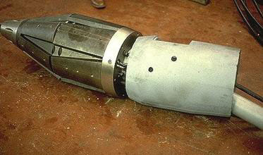
Figure 18. Standard Pipe Bursting Head.(18)
The pipe bursting technique was originated in the United Kingdom and in the United States in the early 1980s. In some countries, it is referred to as pipe cracking. It was originally designed to replace old cast-iron gas mains. With its widespread use as a technique to replace small diameter cast-iron potable water systems, pipe bursting has an increasing worldwide market.(20)
Methods
Pipe bursting involves the insertion of a cone shaped tool, or head, into an old pipe in the insertion pit, as shown in figure 19. It fractures the old pipe and forces the fragments into the surrounding soil. The new pipe is pushed in or pulled in behind the bursting head. The rear of the bursting head is connected to the new pipe and the front end is connected to a cable or pulling rod in the reception pit. To cause the fracturing of the old pipe, the base of the bursting head is larger than the diameter of the old pipe. Its outer diameter is slightly larger than the diameter of the new pipe. This provides space for maneuvering the bursting head in the pipe and also reduces friction on the new pipe.(20)
Figure 19. On-Line Replacement by Pipe Bursting.(20)
The variations in pipe bursting are discussed below.
Pneumatic (or percussive) Pipe Bursting
For this technique, air driven impact moles, also called ground piercing or earth piercing tools as described in the section on impact moling and ramming, are driven forward by a hammer that repeatedly strikes an anvil at the nose of the tool. The mole, with fins, travels up the existing pipe, breaks it out and forces the fragments into the surrounding soil. The percussive fracture mechanism breaks up the existing pipe with its high impact force. This technology is used for brittle materials like cast iron, spun iron, clayware and unreinforced pipe. This is the most popular technique for size-for-size replacement and up-sizing of pressure pipes.(20)
An improvement to this system came in the form of a hydraulically powered rod system to pull the burster through the pipeline. This new method offers increased power control and greater safety to operators and the facility for increased pulling power and larger diameter pipes. The new pipe that is installed is usually polyethylene, pre-welded to the required length. It may be necessary to have intermediate jacking, rather than to have to rely on the pull from the bursting head at the front, or on the jacking force from the rear.(20)
Pipe bursting allows the pipe capacity to be maintained or increased. Therefore the progress rates are much greater when compared to open cut, with less surface disruption.
Hydraulic Pipe Bursting
Since the percussion of pneumatic pipe bursting can be felt on adjacent pipes, services, building foundations and paved surfaces, an alternative, hydraulic pipe bursting, may be used in sensitive areas. This bursting head has petals that open and close under hydraulic pressure. When the hydraulic pipe bursting head is used, it first expands to crack the old pipe, and is then retracted. The new pipe is jacked into place and the burster is pulled ahead. This process is repeated, and more pipes are added to the end as work progresses.
The hydraulic burster is designed to operate with short lengths of product pipes and is primarily for sewerage and gravity pipeline applications, rather than for pressure pipes. Pipelines 1 m (3.3 ft) in diameter have been installed with this method. There is also a portable system that can replace pipes up to 150 mm (5.9 in) in diameter, using equipment that is compact enough for gardens, under buildings and other locations with limited access.
Another variation is to use a powerful hydraulic pushing and pulling machine that acts on high tensile steel rods connected to the bursting head that is pulled through the existing pipeline. The new pipeline is then drawn or jacked behind the head. The typical pulling capacity is 177 to 2046 kN (20 to 230 tons). This method relies more on the power of the pulling machine than on the hydraulic expansion of the head.
New pipes used with the hydraulic pipe bursting method are commonly polyethylene that have joints that snap together. Replacement clayware pipes have also been introduced that allow sewers to be replaced or upsized. Clayware pipes have stainless steel collars to enhance the shear strength at the joints. They can withstand higher jacking forces than most polymeric materials, but they are heavier and may require powered systems for lifting and handling on site.(20)
Pipe Implosion
When using pipe implosion, the pipe fractures inwards prior to the outward displacement of pipe fragments. The procedure is similar to that of pipe bursting.
Rodding
The hydraulic rodding system consists of a static bursting head, fitted with fins, that is pulled through the pipeline by a series of rods. These rods are first pushed through the pipeline by a hydraulically powered rig that is located in the lead trench. The steel rods, approximately 1 m (3.3 ft) long, are pushed into the pipeline individually. After each rod has been inserted, a new rod is threaded onto the previous rod and the process is repeated. At the far end of the pipeline, the bursting head is attached to the rods. As the rods are pulled back, the old pipe is broken open.
Pipe Eating
Pipe eating is a variation of microtunneling. The old pipe is consumed by the tunneling machine as the new pipe is jacked into place. It crushes the existing pipe with an eccentric-cone crusher. This allows realignment and upsizing of the sewer. These systems can also allow on-line pipe replacement without flow diversion. This pipe eating process can be used for the replacement of clayware, concrete, asbestos cement, and reinforced concrete pipes. This system has teeth in the crusher cone that can cut the reinforcement in a concrete pipe, allowing excavation of all conventional pipe materials in addition to the concrete. This technique is suited for large diameter pipes and in situations where the heave caused by expansive upsizing could damage the surface or adjacent services.(20)
Pipe Reaming
Pipe reaming with a horizontal directional drilling machine is a newly introduced technique. A specialized reaming tool grinds up the old pipe as the new one is drawn in behind. The fragments are suspended in drilling fluid and pass through the existing pipe to a manhole or recovery pit.(20)
Pipe Splitting
This system was developed specifically for the replacement of steel pipes. This technique works in a similar manner to rodding techniques, but a splitting head is used to break open the pipe. This head consists of a series of discs that score the inside of the pipe. Blades follow that cut open the pipe. The spreader behind the blade pushes the sections of the pipe open, to allow the replacement pipe to be installed.
If the pipes that are to be replaced are non-brittle, the burster may cease to make forward progress. An alternative approach was developed that uses a cutting and an expanding head that can cut through the wall of a ductile pipe or fitting. This head is pulled through the old pipe by a hydraulic rod system and slices open the old pipe as the new pipe is drawn in behind. It can be used on pipes made of steel, ductile iron, repaired cast iron, asbestos-cement, PVC and polyethylene. Diameters of up to 305 mm (12 in) have been installed under suitable conditions. Rates of progress of 2 m/min (6.5 ft/min) have been recorded.(20,29)
Pipe Ejection
In pipe ejection, the old pipe is jacked towards the receiving pit where it is broken and removed, while the new pipe is simultaneously inserted. This is commonly used with old lead pipes. Lead pipes are a significant health risk when the lead is absorbed into the drinking water. The existing lead pipe is pulled out of the ground and replaced with a new polyethylene pipe. For this technique, a steel cable is inserted into the lead pipe, which expands and grips the walls of the lead pipe. The old pipe is extracted and wound onto a drum. The new replacement polyethylene pipe is pulled in at the same time by the cable. This technique is fairly successful for straight service pipes, but excavation may be required if the pipe has a sharp bend, is surrounded in concrete or has been fitted with flange couplings.(29)
Equipment
For pipe bursting applications to be successful, the pipes should be made of brittle materials like vitrified clay, cast iron, plain concrete, asbestos and some plastics. Reinforced concrete pipe can also be replaced if it is not heavily reinforced or if it has not deteriorated substantially. For ductile pipes (steel or ductile iron) they can be replaced only by pipe splitting.
Specially designed heads can reduce the effects of existing sags or misalignment of the new pipe. The size of the pipe that is typically replaced can range from 51 to 914 mm (2 to 36 in) in diameter. The size of the bursting head is increasing over time, and pipes with diameters up to 1219 mm (48 in) have been replaced. See the previous section for more detailed information on pipe bursting equipment.(29)
Practical Applications
The primary applications of pipe bursting are in gas and water main renewal. It is also becoming more prevalent among trenchless technologies for the replacement of old and undersized sewers. Significant increases in pipe size can be accomplished, as noted in a replacement of an old concrete sewer, about 375 mm (15 in) in diameter, which was upgraded to a 600 mm (24 in) plastic main. Typically, pipes that are burst have diameters between 150 to 375 mm, (6 to 15 in) and have been replaced with pipes 800 to 900 mm (32 to 36 in) in diameter.(20)
The success of the operation depends on having accurate information about the original construction materials and the condition of the existing pipeline. For example, if there have been localized repairs or if the pipeline is encased with concrete, problems could arise during construction that may not have been identified during the planning stages.
Typical lengths for pipe bursting drives are 91 to 122 m (300 to 400 ft) lengths, which is also the typical length between sewer manholes. However, longer drives have been replaced.(29)
Specifications and Guidelines
Pipe bursting is currently being used in California and Texas for water and sewer pipe replacement. See reference 28 and Appendix C. These specifications cover materials, preparation, construction methods, pipe joining, payment and warranties. General guidelines and sample technical specifications for the reconstruction of sanitary sewers by the pipe bursting process are also available.(29) The guidelines in reference 29 provide details on the main classes of pipe bursting, design considerations, and construction considerations. Notable design considerations are the ground and groundwater conditions, surrounding subsurface utilities, and the effect of pipe bursting on nearby structures. However, the pipe bursting process is currently not covered by ASTM specifications, although the plastic replacement pipes are covered.
4.2 Summary of Methods
The previous section provided a basic overview of several different trenchless technology applications. Throughout the section, information regarding the appropriate use of each technique was given. This section provides a summary of information on all the methods described in the previous section. This section includes the following discussions:
- Selecting the appropriate methods based on type of construction and type of utility.
- Advantages and limitations of each method.
- Cost analysis to determine if trenchless is a feasible alternative.
- Safety.
- Project planning.
These sections are intended to provide addition information to help agencies and private industry determine the most appropriate method of trenchless technology, or if trenching is indeed the most appropriate method of utility construction. This is not a complete catalog of methods and applications, and the reader should consult references in the bibliography and a trenchless technology contractor for a detailed analysis of a particular situation.
4.2.1 Finding the Appropriate Method
This section provides information on the various trenchless methods and their applicability to the individual types of utilities and types of construction. The tables contained in this section include not only the methods of trenchless technology described in section 4.1, but other methods that are similar to those, but that were not described in this manual. The four major types of construction include:
- New installation.
- Online replacement.
- Renovation.
- Repair and maintenance.
As mentioned, the technique selected also depends on the type of utility, including:
- Water.
- Wastewater.
- Gas.
- Electricity.
- Telecommunications (including cable television).
The trenchless technology methods most suited for the combination of construction and utility type are shown in the following four tables, which are organized by construction type: new installation (table 14), online replacement (table 15), renovation (table 16), and repair and maintenance (table 17). This information is summarized from reference 18.
| TECHNIQUE | Water | Waste Water | Gas | Electricity | Telecommunications |
|---|---|---|---|---|---|
| Auger Boring | √ | √ | √ | √ | √ |
| Directional Drilling | √ | √ | √ | √ | √ |
| Guided Boring | √ | √ | √ | √ | √ |
| Impact Moling | √ | √ | √ | √ | |
| Microtunneling | √ | ||||
| Mole Ploughing | √ | √ | √ | √ | √ |
| Narrow Trenching | √ | √ | √ | √ | √ |
| Pipe Jacking | √ | ||||
| Pipe Ramming | √ | √ | √ | √ | √ |
| Thrust Boring | √ | √ | √ | √ | √ |
| TECHNIQUE | Water | Waste Water | Gas | |
|---|---|---|---|---|
| Pipe Eating | √ | √ | ||
| Pipe Bursting | Pneumatic | √ | √ | √ |
| Hydraulic | √ | |||
| Rod Pulling | √ | √ | ||
| Splitting | √ | √ | ||
| Pipe Pulling | √ | √ | ||
| TECHNIQUE | Water | Waste Water | Gas | |
|---|---|---|---|---|
| Close Fit Lining | Die drawing | √ | √ | √ |
| Rolldown | √ | √ | √ | |
| Deformed pipe | √ | √ | √ | |
| Service pipe liner | √ | |||
| Continuous Sliplining | √ | √ | √ | |
| Cured in place pipe | √ | √ | √ | |
| Discrete Sliplining | √ | |||
| Ferrocement | √ | |||
| Live Insertion | √ | |||
| Segmental Lining | √ | |||
| Spiral Lining | √ | |||
| Spray Lining | Cement Mortar | √ | √ | |
| Epoxy resin | √ | |||
| Polymeric | √ | |||
| Reinforced Cementitious | √ | |||
| TECHNIQUE | Water | Waste Water | Gas | |
|---|---|---|---|---|
| Air Scouring | √ | |||
| Chemical Stabilization | √ | |||
| Flushing | √ | |||
| Jetting | √ | √ | ||
| Localized Repair | Joint Sealing | √ | ||
| Patch | √ | |||
| Pointing | √ | |||
| Rerounding | √ | |||
| Robotic | √ | |||
| Pigging | √ | √ | ||
| Pressure Scraping | √ | |||
The selection of a trenchless method depends not only on the type of construction and type of utility, but on local attitudes, policies, and regulations. For example, the City of Dallas, Texas, banned directional boring in the downtown area after a contractor hit a water main on Labor Day, 2000. The damage done by the water was over $4.5 million.(30)
Other restrictions on the choice of construction method could also include, among others, ground conditions, availability of trenchless technology contractors and equipment, cost, safety, and the technical feasibility of the various method desired. The appropriate techniques in the preceding tables are only recommendations, and should not be taken as absolute. There will certainly be exceptions to the recommendations in these tables, as various highway agencies, cities, and industry users become more familiar with the technology and its capabilities.
Standard pipe sizes, bore lengths, and depths are also a consideration in determining the appropriate method. table 18 provides an indication of the range of depth, length and diameter of the various methods.
| Range of Application | |||
|---|---|---|---|
| Method | Depth | Length | Diameter |
| Maxi and Midi HDD | < 50 m (160 ft) | 120-1800 m (400-600 ft) | 75-1370 mm(3-54 in) |
| Mini HDD | < 15 m (15 ft) | 12-180 m (40-600 ft) | 50-350 mm (2-14 in) |
| Auger and Slurry Boring | Varies | 12-150 m (40-500 ft) | 200-1500 mm (8-60 in) |
| Pipe Jacking | Varies | No theoretical limit - 490 m (1600 ft) | 1060-3050 mm (42-120 in) |
| Microtunneling | Varies | 25-225 m (80-750 ft) | 250-3000 mm (10-120 in) |
| Impact Moling (Non-Steerable) | Minimum 12 mm/mm (1 ft/in) diameter | 12-30 m (40-100 ft) | 50-150 mm (2-6 in) |
| Impact Moling (Steerable) | Minimum 12 mm/mm (1 ft/in) diameter | 12-60 m (40-200 ft) | 50-200 mm (2-8 in |
| Ramming | Minimum 12 mm/mm (1 ft/in) diameter | 12-60 m (40-200 ft) | 100-1070 mm (4-42 in) |
As described above, the range of application guidelines in the previous table should be used as a general guide in determining an appropriate method for trenchless construction. As technology improves within the various methods, each may expand its range of depth, length, and diameter application.
4.2.2 Advantages and Limitations
This section summarizes the advantages and limitations of the various trenchless technology applications. In general, all trenchless technology applications have the common advantage of reducing the impact to the surface, and to pavement structures. Although some city ordinances consider directional drilling or microtunneling to be a disruption to the pavement structure, the surface of the pavement is generally not impacted.(31)
Other benefits include reduced impacts to traffic, and the other costs or impacts associated with traffic congestion. Although this section includes some reference to cost and safety, they are only made as they relate to the advantages and limitations of the particular method. These will be discussed in more detail in later sections.
Horizontal Directional Drilling
In general, the advantages of HDD are similar to those of the entire trenchless technology industry. HDD allows for rapid installation, and relatively large pipelines can be installed over long distances. The guided bore can be made accurately, and safety is greatly improved when used in conjunction with subsurface utility engineering. Line and level available is controllable, which can also be confirmed by a print out. Mini-HDD equipment is portable, self-contained, and is designed to work in small, congested areas.(17)
Limitations on HDD include the amount of space required to develop the underground access points. A relatively large area may be required for the drilling rig and associated equipment at the drill entry point. Another large area is generally required at the drill exit point, although surface-entry operations can reduce the need for access shafts. Other limitations include the possibility that the bore may collapse in some granular soils and gravels. Ground movement must be considered, especially in midi- and maxi-HDD applications. The pressure and high flow rates of the drilling fluid can cause some excess soil to erode, which leaves a void outside the installed pipe, which may eventually collapse. Additionally, pressure may cause the drilling fluid to flow into a soil stratum as the drilling head advances, potentially causing heaving of that soil layer. Drilling fluid can also seep to the surface in shallow cover. Other limitations include excessive torque and thrust applied to the drill stem, especially in curving boreholes, which can cause drill stem failure in mini-HDD application.(32)
Auger and Slurry Boring
Both auger and slurry boring have decreased risk of disrupting the surface either by subsidence or heaving, but an experienced operator is necessary to minimize the risk. Auger boring can be used in a wide range of soil conditions. Table 5 on page 19 of reference 17 provides extensive information on the influence of ground conditions on auger boring operations. Both auger and slurry boring can be used to install any type of pipe or cable.
Both auger and slurry boring are generally un-steerable, however some basic steering systems are available. Both also require entry and reception shafts. As with any trenchless technology application, a thorough site investigation is recommended, primarily to identify obstacles such as large boulders and soft ground. Auger boring can accommodate larger rocks, up to one-third the diameter of the casing.(17) Slurry boring is generally limited to firm, stable, cohesive soils to limit the risk of bore hole collapse. In auger boring, the casing should be made of steel, to accommodate the steel augers turning inside the casing. Subsidence is possible with overexcavation in slurry boring, but is less of a risk in auger boring. There is a greater risk of heaving, however, in auger boring if excessive force is applied at the excavation face.
Pipe Jacking and Microtunneling
If used properly, both pipe jacking and microtunneling can have a low risk of surface disruption. Subsidence can be kept to about 25 mm (1 in). Pipe jacking has been in use for over 100 years, thus providing a long history of success and much experience in the industry.(17) Curved, steered bores are possible, although the radius of curvature depends on the equipment and the product materials.
As with most trenchless applications, pipe jacking and microtunneling require a skilled operator who can make adjustments based on almost imperceptible changes in the operation of the machines. Again, a thorough site investigation is essential to the success of the project. Access shafts are required at both ends of the drive. Soil characteristics can have a significant effect on the choice and application of pipe jacking systems, including the bore face excavation, which must be properly supported to prevent sudden collapse. Since the definition of pipe jacking compared to microtunneling is that workers are present in the jacked pipe, the safety of the operators is important. Pipe jacking systems require pipes that can transmit the jacking forces expected in the operation.
Impact Moling and Ramming
Impact moling and pipe ramming operations are generally much more simple to operate than other trenchless applications. Due in part to the simplicity of the methods, these types are generally less expensive than other operations as well. Pipe ramming allows larger casings to be installed in a wide range of soil conditions.(17) In open-faced pipe ramming, the casing is fully supported throughout the driving operation, does not present the risk of overexcavation, and does not require water for the excavation.
Most state highway agencies to not consider pipe ramming in their specifications explicitly, but experience has found that many do not oppose the method. Operations in hard soils can be difficult, including the risk of deflecting the impact mole or lead pipe off course due to large rocks, changing soil characteristics, or other obstructions. Impact moles and rammed pipes have little to no steering control, and are used primarily for straight-line bores. Both types present the risk of damaging existing utilities, as do other methods of trenchless technology. Closed-face pipe ramming operations should be at a depth at least 10 times the diameter of the installed pipe.
Pipe Bursting
Advantages of pipe bursting for in-line pipe replacement include the fact that the alignment of the pipe is already established. This type of operation also provides the flexibility of maintaining or increasing the pipe capacity. Compared to open trench operations, the progress of pipe bursting can be much greater. Also, compared to other trenchless operations, there is less vibration, so damage or other impact to nearby services and structures is minimized.(29)
A limitation of this type of operation is that with the bursting of the pipe, and its expansion radially outward, existing utilities can be damaged, if they are not well-defined and located prior to commencing construction. Surface displacement can be extensive, especially in shallow applications, or in less compactable soils. Also, where unexpected conditions are encountered, such as unrecorded repair collars or adverse soil conditions, the operation may need to be stopped and excavation may be required to get past the obstruction. Another condition that generally requires additional excavation is negotiating sharp bends in the existing pipe. Additionally, excavations must be made to connect the new pipe to the existing service.(29)
4.2.3 Potential Impacts
Although trenchless technology methods of utility installation and maintenance generally impact the public and surrounding infrastructure to a lesser magnitude than utility cuts, there are some potential impacts that should be understood. Many of the trenchless methods described in this manual have similar potential impacts, while others have unique impacts that may affect the public or property. The following is a list of some of the potential impacts that should be considered when deciding on trenchless technology for a project:
- Bore hole collapse / subsidence.
- Access / reception pit excavation.
- Ground displacement / upheaval.
- Ground vibrations.
- Worker safety.
Loose, cohesionless, and granular soils are more susceptible to bore hole collapse if a casing is not placed immediately after excavation. Pipe jacking, and auger and slurry boring are most affected by this type of soil with respect to collapse or subsidence.
Pipe bursting can cause outward ground displacement along the pipe alignment. The displacement is typically localized, and their effects dissipate rapidly away from the bursting operation. Some causes for displacement or upheaval include:
- The pipe to be burst is shallow.
- The ground displacement is directed upwards.
- The new pipe diameter is significantly larger than that of the old pipe.
These displacements can also cause damage to nearby utilities if they are within two to three times the diameter of the new pipe.
Ground vibrations can affect the surrounding soil and adjacent structures. This can be caused by pneumatic pipe bursting, as well as impact moling and pipe ramming. Other sources of information regarding the potential impacts and costs of trenchless technology can be found in reference 33.
4.2.4 Cost and Cost Analysis
This section discusses both the components of cost associated with the trenchless methods and the overall conditions to consider when determining the economic feasibility of the methods. It also gives a range of cost for each method of trenchless construction. Such an economic analysis is an important step in determining the appropriate method for construction.
Figure 20. Break-Even Depth for Trenchless Methods in Sewer Construction.(33)
An example of one type of economic analysis is shown in figure 20.(33) In this figure, the range of tunneling costs is approximately constant, regardless of the depth to which the sewer line is placed. The range of trenching costs, however, rises rapidly based on the depth. The information shown in this figure is reasonable, since deeper excavation for trenching methods requires much greater expenditures for labor, safety measures, and equipment. Conversely, trenchless applications do not incur much additional cost based on depth, once the equipment has entered the ground. Some additional costs could be realized in the required depth of entry and exit pits, or time and pipe required to get down to the appropriate depth. This example assumes consistent soil, ground water, and other conditions at the construction site. As conditions change, the break-even depth may change.
If the depth is consistent, a different type of economic analysis may be necessary. For a particular project, the specific costs associated with the available methods should be considered, and compared to traditional trenching methods. In addition to the costs related to construction, the indirect costs and other impacts should be considered. These were discussed in chapter 2. Although it is difficult to quantify many of the indirect costs, such impacts should be included in some manner in the economic feasibility analysis.
Costs Associated with Trenchless Technology
Many of the trenchless methods described in this manual share cost components. Some of the methods have more particular costs associated with the construction, such as boring, pipe ramming, and pipe bursting. The general costs associated with the use of trenchless technology include:(18)
- Capital Cost of Equipment.
This includes drilling rig, boring unit, impact mole, cutting head, jacking unit, control cabin, spoil removal system, power unit, directional control and detection device, and other equipment specialized for a particular method. - Operating Cost.
Equipment setup, operation, and labor costs. - Site Investigation.
A complete site survey should be conducted to determine soil conditions, ground water conditions, water table location, and location of existing utilities and other obstacles. Subsurface utility engineering studies are becoming more popular, and with good location equipment, can save much more than it costs. - Excavation Cost.
Cost incurred while excavating and replacing any required entry and reception pits, or other access points from the surface to the machine as work progresses. - Traffic Management.
In cases where workers or equipment must be in the traveled lanes of highways or streets, traffic control devices must be utilized with a traffic management plan. Such a plan must conform to the Manual on Uniform Traffic Control Devices and any local traffic control regulations.(34) - Product Pipe.
The cost of the pipe to be installed.
Besides the general costs that are associated with most of the trenchless methods described in this manual, other costs that are specific to various methods should also be considered. These include, but are not limited to, the following:
- Steel casing for auger boring, slurry boring, and pipe ramming.
- Sleeving, re-connecting, and overpumping for pipe bursting.
- Electrical strike protection for many of the trenchless methods.
Each of the costs involved in a potential choice for construction should be considered in a cost analysis that compares to traditional trenching. The next section discusses the specific range of costs for many of the trenchless methods described in this manual.
Relative Cost of Trenchless Methods
The cost information in this section is not necessarily current, although the relative values should be fairly consistent over time. Conditions that could change the relative nature of these costs include technological innovation within specific methods that do not cross over into other methods, and governmental regulations that impact specific methods and not others. Other conditions that could effect a change in the relative nature of these costs are also possible. The cost information contained in this section is largely taken from Table 10, page 58 in reference 17.
- Horizontal Directional Drilling
When line and grade are not critical, the following are estimates of the costs associated with HDD. For small diameter installation, the cost is a function of bore length more than diameter. For larger installations, the cost is a function of diameter and bore length.
Mini-HDD: $16 - 164 / m ($5 - 50 / linear ft)
Midi-HDD: $164 - $656 / m ($50 - 200 / linear ft)
Maxi-HDD: $656 - 1640 / m ($200 - 500 / linear ft) - Costs for Auger Boring
$0.39 - 0.52 / mm pipe diameter / m ($3 - 4 / in / linear ft) of pipe if line and grade are not critical
$0.52 - 0.78 / mm pipe diameter / m ($4 - 6 / in / linear ft) of pipe if line and grade are critical - Costs for Slurry Boring
Slurry boring is typically a low cost operation. The equipment is inexpensive and only two to three men are needed. Costs can vary depending on diameter and length of the bore hole; soil conditions; casing installation; and requirements for grouting the casing and the carrier pipe. A nominal value for the unit cost of slurry boring is about $0.13 - 0.39 / mm diameter / m ($1-3 / in diameter / linear ft), when line and grade are not critical. - Costs of Impact Moling
Impact moling is one of the best-suited trenchless technologies for the segments of the gas and water industries that install pipes up to 254 mm (10 in) in diameter with a boring distance of 3.05 to 305 m (10 to 100 ft). Impact moles can be less costly than even the smallest mini-directional drills. Compared to other trenchless technologies on small jobs, impact moling can provide a substantial cost and time savings.(26) - Cost of Pipe Ramming
Pipe ramming is a relatively simple technique and it can be a highly cost-effective solution to short length installation projects. A typical price is $0.39 - 0.78 / mm diameter / m ($3 - 6 / in diameter / linear ft). This price does not include the cost of the pipe or construction of the drive shafts or reception shafts. Drive shafts can cost from $3,000 to $10,000, or more if extensive excavation support is required. The reception shaft is only for soil removal, or retrieval of the drive cone. - Cost of Pipe Bursting
Lateral connections and deteriorated pipe can add significant cost to pipe bursting operations. The number of times lateral connections must be made can be a determining factor when assessing the economics of using pipe bursting as a trenchless replacement method. The limit on the size of the pipe to burst depends on the cost effectiveness compared to conventional replacement, on local ground conditions (potential for ground movement and vibration) and the ability to provide sufficient energy to break the existing pipe and to pull behind the new pipe.
4.2.5 Safety
It is important to maintain jobsite safety throughout any project. Special consideration must be given to trenchless projects, however, due to the level of uncertainty involved in the operation. This section only provides an overview of the steps that should be taken to ensure safety at the jobsite. The following components are essential to have in any safety program. This information is largely from reference 19.
- Safety Plan
The safety plan covers all other aspects of the safety program. It includes emergency procedures for utility strikes and high-risk activities, an emergency evacuation plan, training, method for recording accidents, incidents, and training. - Contingency Plan
In the event of an unforeseen or other unplanned event, a contingency plan must be in place. This plan describes the responsibilities of all those involved in the construction and a course of action for any number of potential events and emergencies. - Responsible Personnel
A safety manager is an important component of a trenchless team. Operators should be well-trained and understand the importance of maintaining a professional attitude throughout the operation. The safety manager and all others involved in the operation should understand the hazards and potential problems that can occur. They should remember that hazards are present in the underground, surface, and overhead areas. - Traffic Control Plan
The safe management of traffic is also important to a successful trenchless operation. This plan should be designed to minimize traffic disruption without compromising the safety of the workers or the public. - Safe Practices and Equipment
All personnel involved should be aware of safe practices and procedures that are in place to protect them, the public, existing utilities, and the public infrastructure.
These components, as part of a formal, written safety program, can help promote responsibility and accountability, and the overall safety and success of the project.
4.2.6 Project Planning
The most important aspect of a trenchless project is likely to be the planning stage. It is at this point in the project development that potential risks and problems can be identified and mitigated. Contingency plans can then be made or adjusted. Alternative plans and design adjustments can be made during the planning process while impacting the project as little as possible. Poor planning can create larger problems during the project, including requiring design changes after construction begins, unexpected utility relocations, etc.
The project planning discussion contained in this section is largely a summary of reference 19. Although this reference is directed at horizontal directional drilling, many of the planning aspects are similar among most methods of trenchless technology. The following seven categories are identified in reference 19:
- Review of Plans, Specifications, and Geotechnical Report
The scope of work is described in the contract documents, as well as the period of performance, design / performance criteria, physical locations and dimensions, products to be furnished and installed, and procedures for quality control, measurement, acceptance, and payment. All parties involved in or interested in becoming involved in the project should understand the contract documents, and have the following questions answered to their satisfaction:- Is the information sufficient for evaluating constructability and estimating the cost of the project?
- Are the project requirements and site conditions adequately described?
- Are site access and period of performance addressed?
- Is the project buildable? If not, what changes are needed?
- Is the period of performance reasonable for completing the project? If not, how much time is required?
- Are the methods, materials, and equipment allowed by the contract documents appropriate? Can the bidder propose or select alternative methods, materials, or equipment?
- What are the permitting and regulatory issues and who are the parties involved?
- Who has responsibility for permits, easements, etc?
- Does the bidder have the resources needed, i.e. expertise, personnel, equipment, and time to construct the project? If not, what are the additional resources needed? Can the be acquired?
- Project Requirements
Project requirements often dictate the equipment, product pipe material, methods, or other aspects of construction. The following list includes items that should be considered when making decisions on both letting and bidding a project:- Intended function
- Diameter
- Depth
- Length
- Cable / pipe material to be used
- Bend radius and bending stress calculations
- Site geometry, topography, and constraints
- Schedule constraints
- Machine size selection
- Drilling fluid system support
- Drilling fluid materials needs
- Surface Investigation and Utility Survey
A surface investigation should be conducted during the planning stages of the project, and again just prior to construction. This includes survey data such as benchmarks, surface elevations, property lines, right of way lines, etc. Regardless of the size of the project or the state of the design plans, the bidder is responsible for the accuracy and completeness of his bid. It is the responsibility of the owner to make the contract and design documents as complete as possible.
A utility survey should be conducted to locate all existing utilities in the area accurately. This can be done by several methods. It is recommended that a subsurface utility engineering study be conducted with as high a quality level as is technically and economically feasible. Possible methods include one-call services, existing as-built plans, ground penetrating radar, and vacuum excavating / potholing. - Geotechnical Site Investigation
Geotechnical evaluation of site conditions for trenchless projects is critical. The types of soils, and their condition is closely tied to the performance of the selected machinery as it bores through the ground. The cost of performing a thorough geotechnical investigation must be weighed against the project cost and potential profit for the contractor. For small projects, most owners will not approve of the expense of a geotechnical investigation, even though such information may be very important to the success of the project. Reference 19 has a detailed discussion about alternative methods of obtaining information for lower cost. - Bore Plan
Bore planning helps to reduce the risk of encountering obstacles and other difficulties by defining a route prior to beginning the bore. Potential obstacles include foundations, structures, existing utilities, elevation differences between the entry and exit locations, and extreme turns. Bore planning tools include devices that both map and help plan the bore. The devices and associated software can help provide alternative plans that minimize potential problems and increase the probability of a successful bore. - Regulations, Permits, and Easements
There are a great number of Federal, State, County, and Municipal regulations and agencies that govern the public ROW, including access to, and construction activities within the ROW. Depending on the project and the regulatory agencies involved, permitting and easements can be easily negotiated, or they can be difficult. It is essential that these issues be considered during the planning stages and schedule1d to ensure that the project is not delayed while the correct permits are obtained and regulations are met. - Other Considerations
Other matters that should be considered during the planning stages of a trenchless project include noise, traffic, fish and wildlife habitat, water resources, drilling fluids clean-up, and historical and cultural resources. As with the section on regulations, permits, and easements, many governmental agencies have regulatory control over some, if not all, of these areas. It is important to know which of these may be impacted by the project and which require special attention during the early stages of the project.
4.3 Subsurface Utility Engineering
To this point, chapter 4 has discussed the various trenchless technology methods, their application, advantages, limitations, and other aspects of the technology. This section is a summary of subsurface utility engineering, its advantages and limitations, and case studies additional technologies that have, and continue to improve the safety, reliability, and technical and economical feasibility of trenchless technology applications.
Some reasons SUE may not have become as widespread in the recent past could be related to the following:
- It has not been used as a professional standard practice in some areas.
- There has been no concerted local or regional effort to educate project owners or engineers on benefits, other than the FHWA effort to educate all state highway agencies.
- There may be a lack of interest by state highway agencies.
- Currently there are few providers nationally.
- Combined construction values are lower in some areas than in others.
- The lack of well-defined standards in the past has created little incentive for changing the status-quo.(35)
Development of SUE methodologies has primarily been on the east coast. However, national standards have been under development, and should be completed in the near future. The American Society of Civil Engineers (ASCE) has developed a standard pertaining to SUE for publication. The official title is ASCE C-I 38-02, Standard Guideline for the Collection and Depiction of Existing Subsurface Utility Data. It will be available from ASCE in September 2002.
Overall, the SUE methodologies have been successful. Of 71 projects studied by Purdue University for economic benefits, only three had a negative return on investment.(36) Subsurface utility engineering has been endorsed and encouraged by AASHTO, FHWA, Association of General Contractors, The National Transportation Safety Board, the Network Reliability Council, and many state highway agencies. The types of people involved in conducting and studying SUE include both office and field personnel, such as highway designers, utility experts, field technicians and specialists, survey crews, records researchers, CAD technicians, geologists, etc.(35)
4.3.1 What is SUE?
Subsurface utility engineering is an engineering process for accurately identifying the quality of subsurface utility information needed for project plans, and for acquiring and managing that level of information during the development of a project. By identifying the quality of the information, engineers and contractors can move ahead with design and construction work with a certain level of confidence in the existing utility data. The design and construction activities can be planned, taking into account the existing utilities, and appropriate clearance can be planned which considers the margin of error in the utility location. This information is based on four quality levels. Each level can be thought of as representing a different degree of risk. Depending on the importance of the project and the potential cost involved in an accident, engineers may justify the expense of a higher quality level and require the utility location information to conform to that quality level. These levels range from A through D, with Quality Level A representing the highest degree of accuracy. The following discussion of the four quality levels is a summary of a discussion in reference 35.
Quality Level D (QL-D) This information is obtained through utility construction records and location activities in the past. This information is very unreliable, and very little, if any, confidence should be given to the data. The contractor is generally liable for the safe negotiation of the underground space, or to locate the utilities on his own. Data of this quality level is generally considered as an "unknown or differing site condition", thus allocating the risk to the contractor.
Quality Level C (QL-C) Information of QL-C enhances that of QL-D surveying and visually locating surface utility features. Risk is assumed by the engineer or surveyor. QL-D information is correlated to that found by the visual inspection.
Quality Level B (QL-B) Utility location data at this level of quality is obtained through geophysical techniques to identify the existence and horizontal location of existing utilities within a standard margin of error. This type of information must be reproducible by similar methods, and must be recorded for later use. As the horizontal location of existing utilities is identified with a more narrow confidence margin, the liability assumed by the engineer also increases.
Quality Level A (QL-A) Information reported as QL-A is of the highest accuracy, which is generally set at 15 mm (0.59 in) vertical, and to applicable horizontal standards. This information is obtained by visual verification of the utility in-place using non-destructive digging equipment. This requires actual exposure of the facility so that location and size can be determined. The liability assumed by the engineer is yet again increased, since construction documents and activities will depend greatly on the accuracy of the utility location data.
4.3.2 Benefits of SUE
Subsurface Utility Engineering has provided many benefits to a large array of agencies and entities, including highway agencies, airports, utility companies, and nuclear power plants. A list of some of the benefits cited in the literature was reported in reference 37:
- Positive visual identification of buried facilities.
- Reduced utility conflicts.
- Significant cost savings.
- Minimum traffic disruption.
- Reduced delays.
- Reduced risks.
- Improved public relations.
- Reduced contingency fees and claims.
- Safer excavation.
- Less disruption of the environment.
- Less damage to utilities.
- Minimum disruption of utility service.
- Fewer field conflicts.
- Fewer project redesigns.
- Improved design schedules.
- More cost-effective designs.
These benefits, and others, have been realized by actual users of SUE. Some of these benefits and cost savings are illustrated in the case studies in the next section.
4.3.3 Case Studies
This section includes short summaries of projects that demonstrate the effectiveness of subsurface utility engineering studies. Many of these summaries are taken from references 35 and 37.
Maryland State Highway Administration
On a highway project in Maryland involving realignment of a state road and widening from 2 to 6 lanes, the use of SUE enabled the Maryland State Highway Administration to redesign the hydraulic system to minimize conflicts with utilities. Instead of relocating 5,000 feet each of gas, water, and sanitary sewer lines, conflicts were reduced and only about 400 feet of each utility needed to be relocated. The cost of SUE was $56,000. Combined cost savings to the state and the utilities amounted to $1,340,000.
Hopkins Road, Richmond, Virginia
A SUE study called for 156 test holes where highway / utility conflicts were seen as possible on a highway project. The data obtained showed that conflicts would have occurred at almost half of the locations. Design changes were made (prior to beginning of construction) and about 80 percent of the conflicts were resolved. The changes early in the project avoided over $731,000 in unnecessary adjustments and change orders later in the project, at a cost of only $93,553.
NC 168, Currituck County, North Carolina
A highway widening project along 18 miles of NC 168 in North Carolina used SUE to identify conflicts with a critical PVC water line. Forty holes were vacuum-excavated (QL-A information), at a cost of only $10,000. Rather than move the entire water line, it was determined that four miles of the water line could remain in place, saving NCDOT about $500,000.
Comanche Peaks Nuclear Power Facility, Texas Utilities
This project utilized three different SUE quality levels for different areas of importance. QL-B information was obtained in more critical areas to develop a plan view of the utility system around the nuclear power facility. QL-C and QL-D information was collected at less critical areas. The owner then obtained a comprehensive map of all utilities in the area, with varying degrees of reliability depending on the relative importance of each area.
Ohio Bell, Lost Nation Road, Willoughby, Ohio
In a politically sensitive area, 29 test holes were excavated to verify data previously supplied to the utility company. Of the 29 holes, six were found to be areas where the existing utility information was in error. Such errors could have cost the utility company in time, money, and embarrassment if they had not been detected.
Reagan National Airport, Washington, DC
On a parking deck project, QL-D information was provided by one contractor. Some time later, another contractor provided QL-B information. An error rate of about 30 percent was found between the two sets of location data, illustrating the benefit of obtaining more accurate data. As seen in other case studies, vacuum excavation can be relatively inexpensive.
4.4 Survey Results and Informal Interviews
As part of the investigation, a survey was conducted among state highway agencies and some cities. The results discussed in this section relate only to those questions in the survey referring to the use of trenchless technology. A summary of the results is discussed in section 4.4.1. Another part of the investigation involved informal interviews conducted primarily by telephone to assess the attitudes of those involved in utilities in and around pavements. Interviews were conducted with representatives from state highway agencies, telecommunications companies, water and wastewater agencies, and others. These informal interviews are summarized in section 4.4.2.
4.4.1 Survey Results
The survey conducted by the research team included many questions regarding right-of-way management and policies, and one section regarding the use and experience with trenchless technologies. Representatives from 30 states and cities responded to the survey. The following subsections contain discussions of responses to the individual questions within the trenchless technology section of the survey.
Has your jurisdiction used or required trenchless technology (TT) in the past?
Of the 30 responses, 29 have used / required trenchless technology in the past.
If so, what has been your experience?
Most responses to this question indicated that the experience has been "generally good". Some of the positive comments indicate the following:
- The price of trenchless is improving.
- Quality is a function of expertise.
- Less traffic impact.
- It is the preferred method.
- Good - but needs more research.
Some of the negative comments about states' experiences include:
- Some conditions prevent use.
- Experienced some poor quality construction.
- A lot of problems with damages.
- Can hit rocks.
What are the major technical obstacles to the successful use of TT in your area?
The following comments were made regarding the major technical obstacles to trenchless technology:
- Accurate utility location.
- Limited ROW for setup.
- Local contractors using outdated machinery.
- Operational quality control.
- Variable soil conditions.
- Operator training.
- Lack of guidelines or specifications.
- Minor pavement damage to riding surfaces.
What are the major attitudes inhibiting the use of TT?
Some of the major attitudes among the state highway agencies which can have the effect of inhibiting the use of trenchless technologies include the following. These are the opinions of the various respondents.
- Trenchless technology is more expensive.
- Need assurance that it will be cost-effective to use.
- Concern for damages to existing facilities.
- Operators are too rushed.
- Users do not thoroughly investigate site.
- "This is how we've always done it!"
- There is a general lack of knowledge about the technology.
In addition to these comments regarding attitudes inhibiting the use of trenchless technologies, six respondents suggested that there are none in their experience.
In your opinion, can pavement utility cuts be reduced through policies, incentives and disincentives, increased availability of information, etc?
Most of the respondents suggested that through policies, incentives, disincentives, availability of information, etc., the frequency of pavement utility cuts can be reduced. Some indicated that this was a possibility, and some had no comment. None of the respondents suggested that this could not be done.
If so, which of these factors would be of the greatest benefit?
Of those indicating that pavement utility cuts can be reduced through those actions mentioned in the previous question, the following were suggested as being the most promising methods, in order of frequency.
- Incentives / disincentives.
- Availability of technical information.
- Moratoria on cutting new streets.
- Requiring bonds and 10-year warranties.
- Encouragement of joint (shared) trenching.
- Advance planning.
- Enforcement of policies.
Summary
Overall, the responses to the trenchless technology section seemed to indicate that many states have had some good experiences in using or specifying trenchless technologies. It is also evident that more information regarding potential policies, specifications, etc., could prove helpful in further encouraging agencies to use trenchless technologies more often.
4.4.2 Informal Interviews
During the course of the project development, several informal interviews were conducted to assess agency and industry attitudes and opinions regarding the use of trenchless technology and other methods to reduce the frequency of pavement utility cuts. This section summarizes the attitudes, usage, and innovative techniques that are used by those interviewed while conducting these telephone interviews.
Attitudes
This section summarizes the attitudes about trenchless technology and utility cuts in general.
- Using Trenchless Since 1995. One state highway agency began using trenchless technology about 1995. It developed a manual regarding its use, but says the technology wasn't good enough at that time to make it work well. Lately, however, the technology is better and they use it wherever possible, which is in the hundreds of projects per year. They have been very happy with the results.
- Cut Permits Include Trenchless. In a new ordinance, one city requires utility cut permits for all construction within the city right-of-way. Although it was intended for utility cuts, it has been interpreted to mean trenchless as well, since trenchless operations also disturb material beneath the streets. Essentially, the permit cost is the same for trenching and trenchless.
- Too Expensive. Many potential users think (right or wrong) that trenchless is too expensive, and therefore do not consider it as a viable alternative. Perhaps the dissemination of good information, the use of pilot projects, advances in technology, and time will change some of these attitudes.
Usage and Innovations
The following are methods of use and innovations, on both the industry and the agency sides, which have proven successful.
- Vacuum Excavation for Visual Location. In urban settings, use a vacuum excavation firm to excavate a hole in the vicinity of existing utilities that may be compromised. If the drilling head enters this hole, it will be seen (visually) and the head is backed up and advanced on the correct path.
- Shared Trenches. When new housing developments are built, require the utilities to share trenches. Some utility companies have taken this a step further and shared construction, as well. For example, the cable company may give their cable to the gas company to install at the same time as the gas lines.
- Safety Meeting. Hold a weekly safety meeting where all utilities in the region are represented and present. Discuss the work schedule for the upcoming week.
- SUE Studies. Require a subsurface utility engineering study for any project where existing utilities or other obstructions may be present.
- Cost Analysis. Utility companies should determine their cost for trenching, traffic control, street cut repair, safety precautions, repair warranties, and other costs. Compare these costs to those associated with trenchless technology.
- Create Database to Track Information. One industry utilities construction manager has developed a database to interface with the city's electronic online cut permit system. Managing over 200 utility cuts and some trenchless projects on any given day, many benefits are realized with such a system. Utility cut ordinance violations can be quickly identified and resolved, coordination between his own crews and the city inspectors are streamlined, and it provides a single point of contact between the city and the utility company.
4.5 Other Technologies and Methods
New technologies are constantly being developed. Many of these complement the trenchless technology industry, and others use different methods of installing or helping install facilities. This section is for informational purposes, and only presents a few typical new technologies. This section does not intend to promote or endorse any particular company or product, nor does it purport to present information on all new technologies that may be available or under development. Some of the promising new technologies include the following:
- North-Seeking Gyroscopic Tool.
Developed in Holland in the 1980s, this technology has been improved to allow use inside the drill pipe during drilling operations. It sends altitude and location information to a computer up to 15 times per second, allowing the device to be used to steer a bore to a specific target or to provide location information after the bore has been completed.(38) - Wireless Applications.
Several wireless devices have been developed to eliminate, or reduce dependence on, hard-wired downhole cables transmitting data back to the computer control station. Such devices may be subject to interference from other magnetic fields and radio waves. - Global Positioning System.
The global positioning system technology has been established and greatly advanced in the past decade. Depending on the accuracy of the receiver and the needs of the user, drilling systems can often be used with this system. Programmed with entry and exit coordinates, the boring system can then steer its way from one end of the hole to the other. Limitations on this technology include the necessity of line-of-sight to the global positioning satellites, and the remaining problem of steering and locating the system between the two points. - Improved Tracking and Mapping Systems.
These systems are being developed to provide operators with more, reliable, and accurate data in real-time. Systems such as this, combined with accurate subsurface utility information, can produce excellent results during boring operations. - City Sewer Installation of Broadband Internet Connection.
At least one company has begun supplying high-speed internet access to the "last mile" in the Nation's major cities. Broadband continues to grow, but the so-called "last mile" from the high-speed internet connection to desktop computers in major urban areas remains a bottleneck. "One of the biggest obstacles to the rollout of high-speed Internet and data services is that companies must tear up city streets to lay fiber-optic cables. That increases costs, sparks lengthy battles over rights-of-way and disrupts traffic."(39) One solution has been to attach fiber-optic cable to the inside of city sewer pipes using small robots. The city of Albuquerque, New Mexico was the first city to install this type of system. Since that time, many cities throughout the world have begun similar installations. - Construction of Large Conduit for Multiple Uses.
The City of Houston has considered a strategy for constructing 1219-mm (48-in) conduits within which all utilities would be contained. This conduit would be made available for public as well as private utilities. With such a large conduit, construction and future installations can be done inside the pipe, rather than additional excavation through the pavement structure.
As technological advances continue, the advantages to the trenchless and other technology industries will also improve. The reliability of trenchless technology will increase, as will the positional accuracy of the boring heads. The probability of striking existing facilities and other objects will also decrease, as location and steering capability improve. Technologies relating to subsurface utility engineering studies will also improve the ability to locate existing facilities and map them accurately for the trenchless equipment operator.
| << Previous | Contents | Next >> |