

| << Previous | Contents | Next >> |
Full-Depth Repairs
5.0 Construction Procedure
The construction and installation of full-depth repairs involve the following steps:
- Define repair boundaries area
- Saw old concrete
- Remove old concrete
- Prepare patch area
- Provide load transfer
- Place and finish concrete
- Cure and insulate concrete
- Saw and seal joints
5.1 Define Repair Boundaries
Repair boundaries can be determined by making a field survey utilizing data from initial project survey. This survey should be conducted as close to the contract schedule as possible. Each distressed area should be examined and the repair boundaries marked on the slab surface. Additional areas of distress that have occurred since the initial survey should be included. If the project plans contain partial-depth repairs, the project specifications should include a special provision that provides the engineer freedom to change some partial-depth repair to full-depth repairs. Partial-depth repairs are only appropriate for spalls within the top one-third of the slab. Guidelines for locating repair boundaries are provided below:
- The recommended minimum repair length is 1.8m (6 ft) for repairs provided with mechanical load-transfer devices, and 2.4 - 3m (8 -10 ft) for repairs with aggregate interlock joints. All repairs should be full-lane width.
- The minimum recommended distance from the full-depth repair joints to the nearest transverse crack or joint is 1.8m (6 ft).
- A boundary that would fall at an existing doweled transverse joint should be extended 0.3 m (1 ft) to include the existing joint.
- If distress is present on only one side of an existing nondoweled joint, that joint may be used as a boundary.
- Reinforcement is needed in JRCP where the patch length is longer than 4.6m (15 ft). It may be more economical to place additional doweled transverse joints at 4.6m interval than to place reinforcement.
On multiple-lane highways, it is generally not necessary to match joints in adjacent lanes, as long as:
- The minimum length requirements are met.
- All of the deteriorated area has been included within the repair boundaries.
- A separation fiberboard has been placed along the longitudinal joint.
- The patch is not tied to the adjacent lane
However, if the distressed areas in both lanes are similar and both lanes are to be repaired, aligning repair boundaries to avoid small offsets and to maintain continuity may be desirable.
5.2 Saw Old Concrete
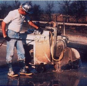 Figure 7. Full-depth Sawing transverse boundaries |
Before removing deteriorated concrete, isolate the area from adjacent concrete and shoulder materials using full-depth saw cuts. The full-depth cuts separate the segment of deteriorated concrete and allows room for its removal with minimal damage to surrounding materials.
It is preferable to use diamond-bladed saws for full-depth transverse cuts. Diamond-bladed saws produce straight, smooth, vertical faces that improve the accuracy of dowel bar placement. Any interior or centerline longitudinal joint also requires a full-depth cut through the existing joint reservoir. To avoid spalling damage during removal, the sawing operation should be continued through the joint. This is to ensure that the base of the blade reaches the intersection with the transverse boundary cuts. If diamond-bladed saws bind during hot weather, then the concrete slabs are in compression from thermal expansion. One way to cure this problem is to saw at night during cooler temperatures, or provide pressure-relief cuts with carbide-toothed wheel saws. The contractor may elect to use one or more wheel saw cuts within each patch area to give removal equipment space to grasp the old concrete.
Sawing of Patching Boundaries for CRCP
The outer boundaries of repair should be cut, partial-depth above the steel reinforcement, with a diamond blade saw. If any of the steel reinforcement is sawed through, the length of the patch must be increased by the lap length required (Figure 8 and 9). The partial depth cut should be located at least 460 mm (18 inches) from the nearest tight transverse crack. They should not cross an existing crack, and adequate room should be left for the required lap distance and center area.
 Figure 8. Required sawcuts for CRCP |
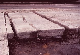 Figure 9. Partial-depth and full-depth sawcuts for CRCP |
After the partial-depth cuts, two full-depth sawcuts are then made at a specified distance in from partial-depth cuts. The distance depends on the method of lapping used to connect reinforcement. The recommended distance is 610 mm (24inches) for tied laps, and 200 mm (8 inches) for mechanical connections or welded laps. This distance may be reduced depending on the required lap length.
5.3 Remove Old Concrete
Sawing operations should not precede removal and repair operations by more than two days. The full-depth cuts provide no load transfer capacity and can begin to pump or punch into the subbase, causing unnecessary damage. There are two basic methods of removing deteriorated concrete from the repair area:
Liftout
It is preferable to lift the deteriorated concrete whenever possible. Lifting the old concrete imparts no damage to the subbase and is usually faster and requires less labor than any method that breaks the concrete before removal.
The most common liftout method uses a steel chain connected to lift pins. Operators drill at least two vertical holes through the old concrete surface, then inserts one lift pin into each hole. The operators fasten the chain to a crane or front-end loader that is capable of lifting the concrete vertically, then swinging it onto a flatbed or dump truck for removal from the site. Other lift equipment includes forklifts, vertical bridges, lateral-pressure lifts and a torque claws.
Damage during liftout is not entirely avoidable and it will probably be necessary to extend the repair if the lifting operation chips the remaining concrete. Damage most often occurs if the old concrete swings during the lift and chips the faces of the remaining concrete. Making a wheel cut within the patch area can provide some additional space for lateral movement.
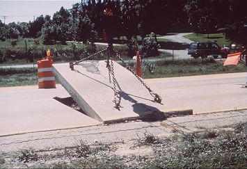
Figure 10. Liftout operation chain for removing existing slab
Breakup
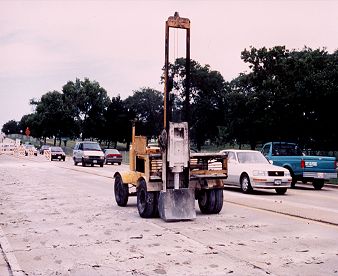 Figure 11. Drop Hammer breaks the deteriorated concrete |
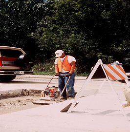 Figure 12 Vibratory Plate Compactors |
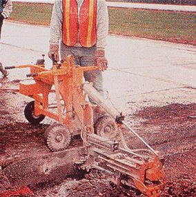 Figure 13 Self propelled slab reference |
 Figure 14 Injecting grout or epoxy and inserting dowels |
Sometimes concrete joints or cracks are so deteriorated that it is unsafe to remove them by liftout. In these cases it is necessary to break the deteriorated concrete into small fragments for removal by backhoe and hand tools. The drawback to this method is that it often damages the subbase and requires more repair preparation than a liftout operation. The damage occurs because the break hammer pushes pieces into the subbase, which requires the backhoe operation to dig into the subbase surface to scoop out broken concrete.
When using mechanized breaking equipment like drop hammers or hydraulic rams, operators must exercise control on the equipment's break energy. Operators should begin breaking the concrete in the center of the removal area and move outward toward buffer cuts. Buffer cuts are made about 0.3m (1 ft) away from the perimeter saw cuts within the patch. The operator should reduce the break energy (drop height) before starting on the area outside the buffer cuts. Then there will be less chance of damaging concrete beyond the patch perimeter.
5.4 Prepare the Patch Area
After removing the old concrete and loose material, the area is ready for subbase preparation. If removing operations damage the subbase, it may be necessary to add and compact new subbase material. Ideal backfill materials can reach optimum compaction with small plate compactors that can maneuver in the confined patch area. Use vibratory plate compactors that have a centrifugal force rating from 17 to 27 kN (4000 to 6000 lb). If the repair area fills with rainwater after concrete removal, the water should be pumped out or drained through a trench cut at the shoulder before repairing the subbase.
5.5 Provide Load Transfer
Drilling dowel holes
Automatic dowel drilling rigs are preferable to single, hand-held drills. It is difficult to drill consistent holes using hand-held drills because they are heavy and do not have an alignment guide or jig. Dowel drill rigs contain one or more drills attached parallel in the rig's frame. The frame acts as the alignment jig to control drill alignment and wandering. However, single, frame-mounted or hand-held drills are necessary where there is not enough room for the multiple-drill rigs.
There are several varieties of drill rigs. The difference depends on their mount and whether they reference the slab or subbase. The three basic types of drill rigs are as following:
- Self propelled, subbase-reference rig
- Self propelled, slab-reference rig
- Boom-mounted, slab reference rig
Standard pneumatic or hydraulic percussion drills provide acceptable drilling results for dowel holes. Both drill a typical 225 mm (9 in) hole in about 30 seconds. Standard pneumatic drills cause slightly more spalling on the slab edge when starting to drill because they impart more energy than hydraulic drills. However, this should not affect dowel performance when good installation techniques are followed.
Hole diameter - The hole diameter depends on the anchoring material. Cement-based grout requires a hole diameter 5-6 mm (0.20-0.25 in) larger than the nominal outside dowel diameter. Epoxy anchoring materials only require a hole diameter about 2 mm (1/16 in) larger than the nominal dowel diameter.
Cleaning Holes - After drilling, clean up the dowel holes with compressed air. Insert the air nozzle holes with compressed air. Inserted the air nozzle to the back of the hole to force out all dust and debris. Dust and dirt prevent the epoxy or non-shrink grout from bonding to the concrete around the hole perimeter. Also, occasionally check the air for oil and moisture contamination from the compressor. The compressor should deliver air at a minimum of 3.4 m3 per minute (120 ft3/min) and develop 0.6 Mpa (90 psi) nozzle pressure.
Installing Dowels - To place the anchoring material, use a long nozzle that feeds the material to the back of the hole. This assures that the anchoring material will flow forward along the entire dowel embedment length during insertion. It also decreases the likelihood of leaving voids between the dowel and the concrete. For non-shrink cementitious grouts, a caulk-gun-type tool is preferable. Do not use any method that attempts to pour or push the anchoring material into the hole.
For epoxies, the injection wand on the installation unit should contain an auger-type mixing spindle that mixes the two-part epoxy. Prefabricated epoxy cartridges are available that supply enough material for one or two holes; a more cost-effective system for large projects uses a pressurized injection system from bulk epoxy containers. While pushing in each dowel, twist the dowel about one full revolution to evenly distribute the material around the dowel's circumference. Without the twist, most of the anchoring grout will remain along the bottom of the bar, and voids will be present along the top of the bar.
Sometimes the anchoring material flows out while inserting the dowels. A plastic grout-retention disk provides a barrier that prevents the escape of epoxy of grout. When metered properly, some anchoring material should be visible from the sides of the disk after installation. If no grout can be seen, there may not be enough in the hole. If retention disks are not available, a laborer should trowel some extra grout around the dowel. This is not an ideal installation, but is preferable to leaving a void.
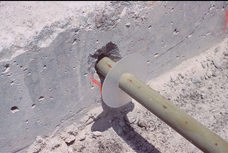
Figure 15 Grout-retention Disk
Prepare Longitudinal Joints - Longitudinal patch perimeter joints also require preparation before adding the new concrete. Full slab replacements and repairs longer than 4.5 m (15 ft) require a tie system. Drill and anchor tiebars or wiggle bolts using the same anchoring grout used for dowels. Either #10M (#3) to #20M (#6) deformed reinforcing bars or two-part threaded couples are acceptable in most specifications. Typically these are spaced along the longitudinal joint at 750 mm (30 in). For repairs less than 4.5 m long, place a bond breaking board along any longitudinal face with an existing concrete lane or concrete shoulder. A thin, 5 mm (0.20 in) fiberboard or similar material should match the repair area depth and length and sit flush with the longitudinal face of the repair. The bond breaker allows the patch and the old concrete to move independently.
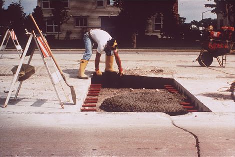
Figure 16 Installation of Bond-breaking Board
5.6 Place and Finish the New Concrete
Placing Concrete - Place concrete into the repair area from ready-mix truck or other mobile batch vehicles. Distribute the concrete evenly to avoid the need of excessive shoveling. Use care to attain good concrete consolidation around dowel bars and along the patch perimeter. Honeycombing reduces concrete strength and durability. Use vertical penetrations of a standard spud vibrator to adequately consolidate the patching concrete. Do not drag the vibrator through the mix this may cause segregation and loss of entrained air.
Finishing & Texturing - Both vibratory screeds and 3-m (10 ft) straightedges are good tools to strike off and finish a repair surface. It is better to pull the finishing tool across the pavement with the blade parallel to the longitudinal joint for short repairs (<3 m(10 ft)). The tool rests on the old concrete on both sides of the repair and follows the surface of the adjoining slabs. The patch surface will then match the surrounding surface profile. For patches longer than 3 m (10 ft), finish the surface with longitudinally with a vibratory screed. Texture the patch surface so that it is similar to the surface of the surrounding pavement. Burlap drag and transverse tined surfaces are common.
Figure 17 Straightedge and Vibrating Screed
5.7 Curing
Curing is important to help the concrete achieve good strength and durability. In general, a liquid-membrane-forming curing compound is adequate as long as it is applied evenly and sufficiently. Use well-maintained pressure spraying equipment that will allow an even application. An application rate of about 5.0m2/L (200 ft2/gal) is sufficient for either material. For some cases insulation mats will be required to increase the concrete temperature and accelerate strength gain. The first few hours after pouring the concrete are the most critical for good curing. Therefore, apply the curing compound and insulation as soon as possible after finishing the surface. To prevent moisture loss and to protect the surface, place one layer of polyethylene sheeting on the patch surface under the insulating boards or mats. Avoid using insulating boards during very warm temperatures, this may caused concrete to undergo thermal shock when they are removed.
Smoothness - A good finishing technique can develop an adequate transition between the patch and old concrete. In some cases, a ride specification comparable to the local ride specification may be needed for CPR projects. Patched pavements that do not meet a specified ride requirement will require correction by diamond grinding.
5.8 Saw and Seal joint
The final step is to form or saw transverse and longitudinal joint sealant reservoirs at the patch boundaries. Sealed perimeter joints will lower the potential for spalling at the patch joints. Hot-poured asphalt-rubber sealants are most commonly specified for longitudinal joints and higher type sealants to such as low modulus silicone are commonly used for transverse joints.
5.9 Opening to Traffic
There are two methods to determine when to open full-depth repairs to traffic:
- Specified minimum strength
- Specified minimum time after completing placement
For most concrete pavement applications, it is preferable to measure the concrete strength to determine when it is acceptable for traffic. This is not always true for concrete repair, particularly where quick opening is critical. Most patch mixes fall into three categories for opening to traffic: 4 to 6 hour, 12 to 24 hour, and 24 to 72 hour (conventional) (Table 3). Small variations in air temperature also influence concrete strength development. Maturity meters, or pulse-velocity devices is preferable to a specified time requirement. An agency may stipulate that the repair attain a minimum strength before it may be open to traffic. Recommended minimum strength for traffic opening are :
- Compressive Strength: 13.8 MPa (2,000 lbf/in2).
- Modulus of Rupture: 2.1 Mpa (300 lbf/in2) center-point loading, or 1.7 Mpa (250 lbf/in2) third-point loading.
| For Mixes Using: | Typical Time to Opening Strength |
|---|---|
| Certain blended cements | 2 - 4 hours |
| Sulfo-aluminate cements | 2 - 4 hours |
| Type III cement with non-chloride accelerating admixture | 4 - 6 hours |
| Type III cement with calcium chloride (CaCl2) accelerator | 4 - 6 hours |
| Type I cement with calcium chloride (CaCl2) accelerator | 6 - 8 hours |
| Type III cement with Type A water-reducing admixture | 12 - 24 hours |
| Type I (air-entrained paving mix without fly ash) | 24 - 72 hours |
| << Previous | Contents | Next >> |