*STARNET
High Level Design
Version 1.0
Prepared for the Sacramento Area Council of Governments
and associated agencies in the Sacramento region
by Siemens ITS

![]()
*STARNET
High Level Design
Version 1.0
Prepared for the Sacramento Area Council of Governments
and associated agencies in the Sacramento region
by Siemens ITS
![]()
|
Document Description |
Date |
Version Number |
|
Initial Draft |
March 30, 2007 |
0.1 |
|
Revised per comments from Technical Advisory Committee (internally) |
May 30, 2007 |
0.2 |
|
Revised per comments and to make consistent with the updated concept of operations and requirements. |
October 29, 2007 |
1.0 |
|
|
|
|
1.1 Computer Systems to be Integrated
1.2 CCTV Cameras to be Integrated
3.1 Caltrans District 3 and California Highway Patrol Regional Transportation Management Center
3.5 Sacramento Regional Transit Systems
3.8 Sacramento Regional Fire/Emergency Management System Computer Aided Dispatch System
3.9 Yolo County Communications Emergency Service Agency Computer Aided Dispatch System
3.10 Yolo County and El Dorado County Transit Agencies
3.11 Other Cities and Counties Systems
3.12 SACOG Transportation Planning Database
List of Figures
Figure 1 - Major Data Flows in STARNET
Figure 2 - STARNET Conceptual Architecture
Figure 3 - Sample STARNET Gateway
Figure 4 - STARNET Overall Architecture…………………………………………… 15
Figure 5 - Regional Display Node
Figure 7 - Caltrans & CHP Nodes
Figure 8 - Sacramento Regional Transit Nodes
Figure 9 - Sacramento County Nodes
Figure 10 - City of Sacramento Nodes
Figure 11 - Sacramento Regional Fire/Emergency Management System CAD Node
Figure 12 - Yolo County Communications Center Node.
Figure 13 - Typical Transit Agency Nodes
Figure 14 - Typical City or County Nodes
The Sacramento Transportation Area Network, or STARNET, is an information exchange network that is used by the operators of transportation facilities and emergency responders in the Sacramento region of California. STARNET enables the real-time sharing of data and live video, and refinement of joint procedures pertaining to the operation of roadways and public transit, and public safety activities. It thereby assists operations personnel in the coordination of their activities and in providing the public with comprehensive information about current travel conditions and options.
This High Level Design document presents one possible approach for implementing STARNET. It is consistent with the STARNET system requirements that will be used in procuring system integration services for the initial STARNET deployment. The system requirements were derived from user needs described in the document titled STARNET Concept of Operations. The reader is advised to review the STARNET Concept of Operations document to gain an understanding of the goals and context of STARNET.
The goals of the High Level Design Document are:
1. To provide a basis for refining the estimated cost of STARNET deployment and to facilitate obtaining funding.
2. To delve deeper into the system requirements, to verify that the requirements as written can be implemented, to identify clarifications that may be needed in the wording of requirements, and to identify modifications to requirements that may simplify the design and reduce implementation costs while still addressing user needs.
3. Provide the System Integrator additional information to assist in clarifying the requirements and objectives of STARNET.
The STARNET systems integration contractor will be free to use any high level design they may choose to meet the system requirements. Use of all or any of the high level design presented here is not mandatory.
The system requirements are contained in a separate document.
The initial implementation of STARNET involves the computer systems described in Table 1.
Table 1 - Computer Systems to Serve as a Data Source or Sink
|
Host System |
Status |
Data |
Host System Interface |
|---|---|---|---|
|
California Highway Patrol, Computer Aided Dispatch system (http://cad.chp.ca.gov) |
Existing |
Source for roadway incident data. |
XML via FTP with RSS notification of changes. |
|
Sacramento Regional Fire/EMS Communications Center, Computer Aided Dispatch system (Northrop Grumman COBOL CAD). |
Existing |
Source for incident data |
Database read. |
|
Yolo County Communications Emergency Service Agency, Computer Aided Dispatch system (Northrop Grumman Altaris CAD) |
Existing, but may change |
Source for incident data |
Database read. |
|
City of Sacramento Police Computer Aided Dispatch System |
Existing |
Source for incident data. |
XML. |
|
County of Sacramento Lane Closure System |
Existing |
Source for planned and unplanned lane closure data (treated as incidents). |
HTML files available on Internet via HTTP. |
|
Caltrans Lane Closure System |
Existing |
Source for planned lane closure data (treated as incidents). |
ASCII file freely available on the Internet via HTTP (http://www.dot.ca. gov/travel/dist_03/lcs/ lane_closures_d3_xy .txt) |
|
|
|
|
|
|
Caltrans District 3, Advanced Traffic Management System (ATMS) |
Existing |
Source for static data defining ramp meters, and CMS on freeways, & changeable message sign data. |
ASCII files freely available on the Internet via HTTP (e.g., http://www.dot.ca. gov/travel/dist_03/ webinit.txt) |
|
Caltrans, Performance Measurement System (PeMS - http://pems.eecs.berkeley.edu) |
Existing |
Source for static data defining detector stations on freeways. |
XML file freely available on the Internet via HTTP. |
|
Caltrans, Performance Measurement System (PeMS - http://pems.eecs.berkeley.edu) |
Existing |
Source for five minute processed loop detector data (volume, occupancy, speed) for freeways. |
Comma delimited ASCII file freely available on the Internet via FTP. |
|
Caltrans District 3, Front End Protocol Translator (FEPT). |
Existing |
Source for freeway ramp meter data. |
RPC-based. |
|
|
|
|
|
|
Sacramento Regional Transit District, Central Train Tracking system |
Existing |
Source for LRV location data. |
SQL Server database query (e.g., indexed view). |
|
Sacramento Regional Transit District, Incident Tracking System |
In development by Regional Transit (RT) |
Source for RT service disruption incidents |
SQL Server database query (e.g., indexed view). |
|
Sacramento Regional Transit District (RT), Ridership Statistics System |
Existing |
Source for RT ridership statistics |
SQL Server database query (e.g., indexed view). |
|
Yolo County Transit Management System |
Existing |
Source of incident and ridership statistics data. |
SQL database query. |
|
El Dorado County Transit Management System |
Existing |
Source of incident and ridership statistics data. |
Incidents via e-mail. Ridership statistics via database read. |
|
|
|
|
|
|
Sacramento County, VMS 330 traffic signal systems |
Existing |
Source for traffic signal and detector data. |
Via the VMS 330 Proxy Server - format to be determined. |
|
Sacramento County, ACTRA traffic signal system |
Existing |
Source for traffic signal and detector data, and signal commands. Sink for detector data and signal commands. |
XML – based on NTCIP 2306 + TMDD.. |
|
City of Sacramento, TransSuite traffic signal system |
Existing |
Source for traffic signal and detector data, and signal commands. Sink for detector data and signal commands. |
XML – based on NTCIP 2306 + TMDD. |
|
City of Roseville, ATMS Now traffic signal system |
Existing |
Source for traffic signal and detector data. Sink for detector data. |
XML or SQL database |
|
City of Elk Grove, ATMS Now traffic signal system |
Existing |
Source for traffic signal and detector data. Sink for detector data. |
XML or SQL database |
|
City of Citrus Heights, traffic signal system |
Existing |
Source for traffic signal and detector data. Sink for detector data. |
XML or SQL database |
|
|
|
|
|
|
City of Sacramento, Parking Management System |
Existing |
Source for parking garage occupancy data. |
To be determined – assume database read. |
|
|
|
|
|
|
SACOG Transportation Planning Database |
Existing |
Sink for many data. |
To be determined – assume XML push. |
|
SACOG, Regional Transportation Management Display system (aka Regional Display) |
To be provided by STARNET integrator |
Source for incident data. Sink for most data. |
To be determined by the STARNET integrator |
|
SACOG, 511 Telephone System |
To be provided by others. |
Sink for incidents, slowdowns and parking data. |
To be determined. Assume XML push. |
|
Third Party Data Feed server. |
To be provided by STARNET integrator |
Sink for most data. |
To be determined by the STARNET integrator. |
The initial implementation of STARNET involves providing operators (via the Regional Display web-browser-based interface) and the public (via the 511 web site) live streaming video from closed circuit television cameras as follows.
Table 2 – Video Systems to be Integrated
|
Agency |
Type of Camera |
Approx. No. of Cameras Mid 2007 |
Interface Information |
|
Caltrans District 3 |
Cohu analog Pan Tilt Zoom |
20 |
Windows Media Services |
|
Sacramento County |
Cohu analog Pan Tilt Zoom |
44 |
Motion JPEG and Windows Media Services |
|
City of Sacramento |
Analog Pan Tilt Zoom |
30 |
Analog and TBD |
|
Roseville |
IVC 3130-LL-NCS digital Pan Tilt Zoom with integral Axis encoder |
70 |
Motion JPEG and MPEG-4 |
|
Citrus Heights |
Cohu analog Pan Tilt Zoom |
5 |
Analog |
|
Elk Grove |
IVC 3130-LL-NCS digital Pan Tilt Zoom with integral Axis encoder |
1 |
Motion JPEG and MPEG-4 |
|
Regional Transit |
Fixed |
20 (of use to other agencies) |
MPEG-4 |
The concept of operations is fully described in the STARNET Concept of Operations. The description here provides only a brief overview.
Public agencies in the Sacramento urban area will exchange real-time information among themselves to facilitate improved coordination, and therefore effectiveness, of their transportation and emergency response activities. These agencies will also provide relevant real-time information to travelers via the region’s 511 travel information distribution system.
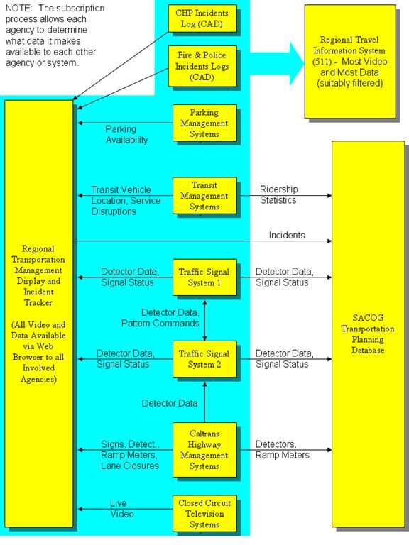
As illustrated in Figure 1, real-time information will be extracted from the various computer systems operated by the involved agencies and appropriate portions thereof will be sent to a Regional Transportation Management Display system, the 511 travel information system, and the SACOG Transportation Planning Database. Some information will also be sent to peer systems operated by other agencies. The information transmitted will include data and streaming live video.
The following are the categories of different users or consumers of the transmitted information. A STARNET organization is one that directly provides or consumes exchanged information. Non-STARNET organizations may obtain a one-way feed of selected information from the 511 travel information system.
· Operators in STARNET organizations
· Computers operated by STARNET organizations
· Computers operated by non-STARNET organizations
· Planners at SACOG
· The public
Operators in STARNET organizations will use the Regional Transportation Management Display (also referred to as the Regional Display) to view data and video describing current conditions, and to enter information about current incidents and planned events. Computers operated by STARNET organizations will use real-time information to make decisions, alert operators, and take automatic actions in support of more efficient transportation system operation and emergency response. Computers operated by non-STARNET organizations may use real-time data for various purposes such as enhanced travel information distribution services, transportation research, and transportation system performance monitoring. Planners at SACOG (the Sacramento Area Council of Governments) will use historical data gathered in the Transportation Planning Database to measure the transportation system’s past performance and as input to transportation models used to predict its future performance. The public will use real-time travel information (data and video) to gain knowledge of current travel conditions, to make decisions about the time, mode, and route of travel, and to estimate and inform others of their likely time of arrival.
Figure 1 - Major Data Flows in STARNET
Terms used in this document are defined in the Terminology section.
There are many factors to consider when developing the architecture for STARNET, such as:
· The agencies participating in STARNET are equal peers. There is no institutional hierarchy and no hierarchy of systems.
· Each agency needs to retain control of its facilities and information. An agency can grant permission to others for access to data or to control their devices.
· STARNET should be designed to minimize the impact of a single point of failure. Peer-to-peer data exchanges should not rely on a central node.
· To facilitate future STARNET expansion and subscription-based many-to-many data exchanges, STARNET needs to follow established center-to-center standards.
· The agencies have existing deployed management systems that predate, or otherwise do not have, a center-to-center interface that complies with the adopted standards.
· Separately modifying each existing system’s software to add an integrated standard interface is likely to be prohibitively expensive and perhaps not feasible in some cases.
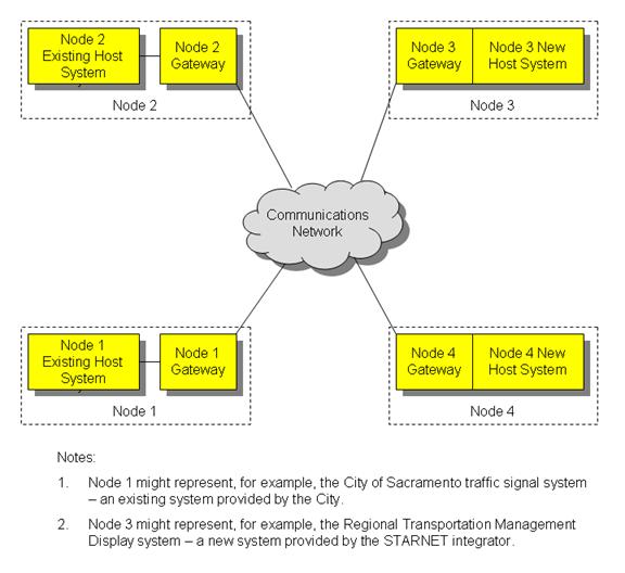
Considering the above factors, the architecture adopted for the high-level design is such that the computer systems involved in STARNET are interconnected in a mesh network. Any computer system can obtain data directly from any other computer system. There is no hierarchy or centralization.
To minimize modifications to existing systems, and to maximize re-use of software, the high-level design adds a “gateway” service in front of each existing system. The gateway service is primarily a translator between the standards-based center-to-center network interface on one side, and whatever unique interface is available on the host system. New nodes, such as the Regional Transportation Management Display, and the 511 system, may have the gateway functionality “built in”, but it is still shown as a separate module for consistency.
The host system and its gateway combined are called a node. Future new host systems procured by agencies may have the gateway functions incorporated and therefore be able to connect to STARNET without modification and without any need for a separate gateway module.
The Regional Transportation Management Display (also called simply the Regional Display) provides a region-wide information display for all STARNET operators and a shared incident tracker. The 511 system provides a region-wide travel information display and interactive telephone service for the public. The 511 system consists of a Third Party Data Feed, video distribution system, 511 Web Page and an interactive telephone service. The Third Party Data Feed, 511 web page dynamic elements, video distribution system, and the gateway to the interactive phone system are part of the STARNET System Integrator’s scope of work. The 511 telephone system and the remainder of the 511 Web Page are under development via separate efforts, and are not part of this design. The 511 Third Party Data Feed provides a gateway to serve as a single point of connection for third parties wanting to subscribe for real-time data available from any of the STARNET nodes, to the extent that agencies wish to make their data available to third parties.
Initially, most data will flow from a gateway to the 511 and Regional Display systems. Exchanging data through STARNET, several traffic signal systems will receive vehicle detector data from remote cities and/or Caltrans and incorporate that data into their existing traffic signal system displays and operation. STARNET will also allow traffic signal systems operated by the County of Sacramento and the City of Sacramento to exchange signal pattern change requests. In the future, other agencies may choose to receive available STARNET data and incorporate that data in their own systems. Figure 1 above, illustrates the initial expected data flows.
Each STARNET node is logically comprised of a “host system” and a “gateway.” The gateway provides STARNET interface functionality, including management of subscriptions and publications, and translation between STARNET and host system data formats and communication protocols. The host system provides the remainder of the functionality of that node. For existing host systems, the gateway will be provided by the STARNET system integrator and will likely function on a new computer separate from any computer used by the existing host system. The Regional Transportation Management Display node will be provided in its entirety by the STARNET system integrator. In this case, the gateway may be integral with the host system. Figure 2 illustrates this architectural concept, of all nodes having at least a logical gateway. The gateways communicate with each other using a single standard protocol and message set. On the other hand, each node may use a different protocol and message set for “internal” communications between its gateway and its host system.
Figure 2 - STARNET Conceptual Architecture
The gateways at different nodes have similar functions and software processes. The types of data exchanged with the node are dependant on the type of host system. Figure 3 illustrates a sample gateway that interfaces a city traffic signal system, the data exchanged and the processes that it performs.
Figure 3 - Sample STARNET Gateway
Permissions Subscriptions Vehicle Detector Data Traffic Signal Data Host System Interface Traffic Signal Data Logger Center to
Center Interface Node
Admin Subscription
Manager Format/ Protocol Translator
![]()

![]()
![]()
![]()
![]()
![]()
![]()
![]()
![]()
![]()
![]()
Due to dependence on legacy interfaces, communications between a host system and its STARNET gateway will likely use different messages, or other data transfer techniques, than the center-to-center standard protocol and messages used between nodes. At each gateway there is a unique Host System Interface that communicates with the host system to send and receive data. Data exchanged between the host system and the Host System Interface use whatever data retrieval processes and format are available in the host system.
Data, once received via the Host System Interface, are then translated in the Format/Protocol Translator to the communications formats and protocols used between nodes and as defined in the NTCIP, TMDD, and IEEE standards. The Format/Protocol Translator is unique to each host system. The Format/Protocol Translator can both translate data from the host system to standard center-to-center interface, as well as translate data received from the standard center-to-center interface to the formats and protocols used by the host system, as required. If the host system does not provide a time stamp for the data, it is added in the Host System Interface.
The Center-to-Center Interface receives data from the Translator and publishes those data in accordance with active subscriptions. The Center-to-Center Interface can also receive data published by remote nodes and provides those data to the Translator. Data are formatted for transport in both NTCIP XML-Direct and NTCIP XML-Soap feeds, with the latter assumed to be used by default.
For each center-to-center message sent and received by a node, the Logger process stores on disk a historical record containing the message type, direction of transmission (sent or received), ID of the destination or origin node, and time of transmission. The resulting log is called the Center-to-Center Message Log. The log can be sorted and filtered.
The Node Administration process allows a Node Administrator to set permissions for subscription requests from other nodes. It also allows a Node Administrator to set up subscriptions to data from other nodes. The Node Administration process monitors transmissions received from remote nodes and maintains a list of nodes that it has detected as non-communicative.
The Subscription Manager process allows a user to establish various types of subscriptions (one-time, periodic, or on-change) and sends subscription messages to other nodes accordingly. It also provides the list of current subscriptions upon the request of a remote node. The Subscription Manager process monitors transmissions to other nodes (in accordance with their subscriptions) and sends “keep alive” messages as necessary.
To promote integration and interoperability, the requirements indicate that data exchanged between STARNET nodes, including the Regional Display, the 511 telephone system, and the 511 Third Party Data Feed shall be based on the NTCIP 2306 Center-to-Center XML standard, IEEE 1512 standard, and the Traffic Management Data Dictionary standard, as appropriate and customized as necessary.
The Traffic Management Data Dictionary defines data elements and messages for traffic management systems, including information pertaining to field devices and incidents from a traffic operations point of view. IEEE 1512 similarly defines data elements and messages for emergency response support systems, such as police/CHP CAD, including incidents from an emergency responder's point of view. These standards defining the content of the messages for each object are currently under development. A message is made up of data elements. The implementation will be compliant with the message content standards to the extent possible, adding custom elements where the standard does not support the requirements.
The NTCIP 2306 Center-to-Center XML standard defines the transmission methods to be used for delivering messages. Any message can be delivered using the NTCIP 2306 standards. This standards defines the publish and subscribe mechanisms used to access data via messages, and the SOAP and Web Service mechanisms used to transport the messages from center to center. All center-to-center messages will be transported using methods compliant to NTCIP 2306.
With a compliant NTCIP 2306 implementation, each computer system can establish a persistent request (subscription) with any other computer system to have real-time data automatically sent (published) either periodically or upon change. Hence data can flow continuously and without human involvement, other than configuration of subscriptions. A computer system may choose to reject a subscription so that agencies maintain control of what data are allowed to flow to what other computer systems.
This high level design assumes that when a Regional Display operator or 511 user selects a camera from the Regional Display or 511 user interface, they are presented with a camera viewing and control (if they have control permission) web page delivered to the web browser directly from the CCTV Camera Control and Video Stream Server for that camera, and that this server is local to the camera in question. The video stream and any camera control commands generated by the operator’s interaction with that page therefore do not involve node-to-node communications and do not use the NTCIP center-to-center protocol and standard messages. In any case, the NTCIP and related standards do not address streaming video.
STARNET operators that are not co-located with the Regional Display node, use the Internet to access the Regional Display user interface. The Internet will also be used for communications between most nodes. Integrating STARNET communications over a public network requires network security measures to be implemented.
Regional Display administrators and gateway administrators at other nodes, are required to enter a user name and password to gain access to the node’s user interface. Firewalls will additionally protect against unauthorized intrusion by allowing network administrators to restrict through traffic based on origin or destination addresses, protocols, direction of traffic, and other filters. For node-to-node communications (gateway-to-gateway), technologies such as Virtual Private Networks, Transport Layer Security, and Secure Sockets Layer will be used instead of or in addition to firewalls, where appropriate.
Firewalls at a STARNET node can be located on the host system side of the gateway, on the Internet side of the gateway, or both. The detailed design will choose between these options, taking into account the owning agencies’ information technology policies and preferences.
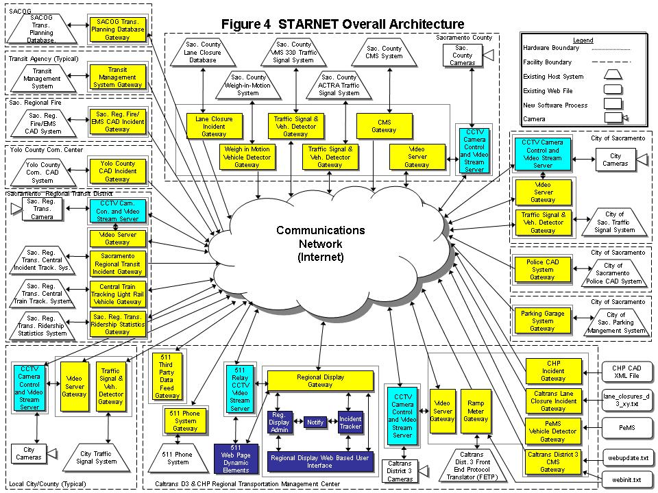
Presented in this section is an overall architecture for STARNET and a discussion of each component by agency or location. The following STARNET Overall Architecture diagram (Figure 4) is consistent with the STARNET requirements. The diagram indicates existing host systems, and new components including gateways at existing host systems. The diagram decomposes the new Regional Display System and 511 System nodes into various processes. To simplify the diagram, back up servers, failover components, and firewalls have been omitted.
Existing components and those under development by others, are shown in white. Existing host systems are shown as white trapezoids. Rounded corner rectangles denote source data that are contained in a file available on the Internet. Colored rectangles are new software processes or components provided by the STARNET systems integrator.
Dashed lines designate facility and hardware boundaries. Long dashed lines denote those systems located in the same building, although they could be located in different rooms within the building. The dotted lines indicate proposed computer hardware boundaries.
Hardware boundaries are shown primarily to define which components are to be on separate computers. Gateways are typically located on a separate server from the existing host system. Typically the CCTV Camera Control and Video stream server is on a separate server. The Regional Display server is separate from the Caltrans related gateways and the 511 system servers, even though they are all located at the Caltrans TOC. As with all elements of this high level design, the system integrator is free to use different hardware arrangements as long as the system requirements are met.
This section also contains a discussion of each component shown on the following STARNET Overall Architecture diagram. The discussion for each component contains an overview of the function the component is expected to perform and its initial configuration.
![]()
![]() There
are eight nodes to be located at the existing Caltrans District 3 and California
Highway Patrol (CHP) Regional Transportation Management Center (also called
simply Caltrans TOC) in Rancho Cordova. These nodes are: the 511 Telephone System
node, the Regional Display System node, a ramp metering node, a changeable
message sign node, a Caltrans Planned Lane Closure System node, CHP Incidents
node, a Performance Measurement System (PeMS) vehicle detector node, and a
video distribution node.
There
are eight nodes to be located at the existing Caltrans District 3 and California
Highway Patrol (CHP) Regional Transportation Management Center (also called
simply Caltrans TOC) in Rancho Cordova. These nodes are: the 511 Telephone System
node, the Regional Display System node, a ramp metering node, a changeable
message sign node, a Caltrans Planned Lane Closure System node, CHP Incidents
node, a Performance Measurement System (PeMS) vehicle detector node, and a
video distribution node.
For discussion purposes, the nodes located at Caltrans District 3 are discussed in the following groups: Regional Display System node, 511 System Gateways, Data from Caltrans nodes, and CHP Incidents node.
In this high level design, the Regional Display system node is considered to consist of seven software processes: Regional Display Gateway, Regional Display Administration, Incident Tracker, Regional Display User Interface, the Notification process, the 511 Relay CCTV Video Stream Server, and the 511 web page dynamic elements. Figure 5 depicts that the Regional Display Gateway, Regional Display Administration, Incident Tracker, Regional Display User Interface, and the Notification process processes are all located on one server, though that is not essential. The 511 Relay CCTV Video Stream Server is shown on a separate server. The 511 web page dynamic elements can be located on a separate server or combined with other processes depending on the detailed design and security concerns. To simplify the diagram below, it does not attempt to show data flows to cell phones from the notification process, nor a universal time acquisition for keeping the server clock set accurately.
Figure 5 - Regional Display Node
The Regional Display Gateway receives center-to-center (C2C) messages from other nodes for incidents, vehicle detectors, light rail vehicles, buses, traffic signals, ramp meters, changeable message signs, parking garages, non-communicative nodes, keep alive messages, subscriptions requests, list of current subscriptions, and camera configuration and, as needed, translates (if needed) the data in those messages into the format used within the Regional Display node.
The Regional Display Gateway retrieves incident information from the Incident Tracker database and creates center-to-center (C2C) incident messages for publication to other nodes as specified in subscriptions received from those other nodes. The Regional Display Gateway can publish incident data to any gateway on the network. To meet the STARNET requirements the 511 Telephone System Gateway, 511 System Third Party Data Feed, and SAGOG Transportation Planning Database each subscribe to incidents published by the Regional Display Gateway.
The Video Server Gateways located at the various agencies, including the 511 Relay CCTV Video Stream Server, subscribe to the Regional Display Gateway for operator permissions and camera configuration data.
Like all node gateways, to meet the STARNET requirements the Regional Display Gateway’s subscription manager sub-process allows an administrator to establish subscriptions for data from (the gateway at) other nodes. The Regional Display subscribes for data from all other nodes. However, it subscribes for only the list of non-communicative nodes from the SACOG Transportation Planning Database Gateway, the 511 Telephone System Gateway, the 511 System Third Party Data Feed Gateway, and the Sacramento Regional Transit Ridership Statistics Gateway.
Like all node gateways, the Regional Display Gateway also allows an administrator to pre-define the types of messages it is willing to accept subscriptions for from each other node, thus enabling received subscription requests to be vetted and either accepted or rejected accordingly.
Like all node gateways, the Regional Display Gateway monitors communications from the nodes from which it is expected to receive center-to-center messages (including keep-alive messages) and publishes a list of non-communicative nodes. The gateway also monitors its publications to other nodes and sends keep alive messages when necessary.
Like all node gateways, for each center-to-center message sent and received by the gateway the Regional Display gateway stores on disk a historical record containing the message type, direction of transmission (sent or received), ID of the destination or origin node, and the time of transmission, in a Center-to-Center Message log.
The Regional Display Administration Process allows an administrator to control access to the Regional Display User Interface by providing an administrator the ability to:
1. Establish operators by assigning each a user name and password
2. Establish user groups and assign users to groups and privileges to groups (e.g., view incidents, create/edit/delete incidents, view camera, control camera, etc.).
3. Set system configurable parameters such as color codes and time thresholds.
4. Configure video feeds such as by setting frame rates, quality levels, and bandwidth for each camera on each CCTV Camera Control and Video Stream Server.
5. Set the primary and backup maintenance person to be paged when a node is detected as non-communicative.
The Regional Display Administration process exchanges data with the Regional Display User Interface and the Regional Display Gateway. Video Server Gateways subscribe to the administration data published by the Regional Display Gateway to receive information regarding operator privileges and video feed configuration.
The Incident Tracker process receives incident information from the Regional Display Gateway (as received from other nodes) and from the Regional Display User Interface. It automatically creates, updates, and deletes records in accordance with incident information received from other nodes via the gateway. It also allows Regional Display operators (users) to create, edit and delete incident records, including editing of automatically created incidents.
The Incident Tracker parses the data received from other nodes and populates the incident record, including the type, location, route, area, announce time, impact, etc. The Incident Tracker also converts abbreviations and codes to a more readable format. The Incident Tracker filters out any inappropriate words or phrases before making such data available to the 511 system. The filtering and abbreviation conversion is configurable by an administrator.
The Incident Tracker scripts the message that will be announced on the 511 telephone system and allows the operator to edit and preview the voice message generated by the 511 telephone system. The 511 telephone voice message maybe generated using text to speed conversion, concatenated speech, or a combination of both. The details regarding the voice generation and how best to structure the incident entry form will be determined during implementation in coordination with the 511 Telephone System Integrator.
All incident records, both those created automatically and those created manually by operators, are available to the Regional Display Gateway for publication, such as to the 511 Telephone System Gateway and the 511 Third Party Data Feed. They are also available to the Regional Display User Interface for display to operators and the 511 web page dynamic elements for display to users.
In the Incident Tracker, each incident record is assigned a unique incident identifier. The Incident Tracker process allows operators to manually create and edit incidents via the Regional Display User Interface. Incident records, both current and past, can be manually merged and/or edited. The Incident Tracker receives information regarding user’s privileges to create or edit incidents from the Regional Display Administration process
Each incident record includes a “whiteboard” field containing free-form textual information relevant to the incident. The Incident Tracker automatically tags each whiteboard entry with the author’s name, agency, and time of entry. The whiteboard also contains an entry for each change to other fields in the incident record.
For each incident record created, the Incident Tracker stores on a disk a historical record containing the entire record of the incident as it stands when its end time is set to actual, or when it is deleted, whichever occurs first. This is called the Incident Log.
At the end of each day the Regional Display stores on disk a historical record containing the minimum and maximum number of objects of each type displayed in the Regional Display during that day. This is called the Objects Count Log.
All logs can be viewed from a user interface on the Regional Display and can be access fro a particular time period. All or select parts of each log can be exported to comma separated variable formatted files.
The Regional Display is also responsible for identifying slowdown areas using Caltrans freeway data. Slowdowns are identified in the Regional Display and announced in the 511 Telephone System. Although slowdowns are not considered incidents, the Incident Tracker may be the component within the Regional Display that identifies slowdowns.
The Notification process receives input from the Incident Tracker and the Regional Display User Interface processes and sends text messages using Short Message Service (SMS) to operators when operator-defined triggers occur. The process of monitoring incident records for defined triggers could occur in either the Incident Tracker process or the Notification process. The Notification Process informs the Incident Tracker when the person has responded to the notification, so that the incident record can be flagged accordingly. Operators do their own notification setup via the Regional Display User Interface process.
Also from the Incident Tracker user interface, operators can send a pop up message to logged in operators or email message to any operator. The Notification Process monitors for the receipt of the acknowledgement from the pop up message and sends notification to the originator of the acknowledgement status.
The Regional Display User Interface receives data from the Regional Display Gateway and the Incident Tracker and incorporates that data in a web based user interface. Access to the User Interface is limited to authorized operators. Operators’ privileges are defined in the Regional Display Administration Process and provided to the Regional Display User Interface. Configuration of the Regional Display User Interface is managed in the Regional Display Administration process.
The user interface displays a map with color-coded icons representing the different field devices, nodes, and incidents. When a user mouses over such an icon, they see all current data related to that object except for incidents for which the 511 message is displayed. By a click on the icon or other convenient means, the operator launches a table displaying all current data for all objects of that type, with the table automatically scrolled to the selected incident. In this table, the text for a particular object is the same color as the corresponding icon on the map. By a click on this incident row in the table or other convenient means, the operator returns to the map view with the map panned so that the icon for that incident is at the center of the map (at its previous zoom level), or as close thereto as possible if close to the map edge. The data and icon/table entry color codes update automatically as conditions change.
From an incident icon or corresponding incident table row, the Regional Display User Interface allows an authorized operator to enter edit mode for that incident. From a camera icon or corresponding camera table row, the User Interface allows an authorized operator to launch the video feed, and camera controls if appropriate, for that camera.
The 511 web page dynamic elements receives data from the Regional Display Gateway and incorporates that data in a web based user interface that is linked to by the 511 Web Page under development by SACOG. Configuration of the 511 web page dynamic elements user interface is managed in the Regional Display Administration process.
Similar to the Regional Display user interface, the 511 web page dynamic elements user interface displays a map with color-coded icons representing the different field devices, nodes, and incidents. When a user mouses over such an icon, they see all current data related to that object, except for incidents for which the 511 message is displayed. By a click on the icon or other convenient means, the operator launches a table displaying all current data for all objects of that type, with the table automatically scrolled to the selected incident. The table views function the same as they do in the Regional Display. Data can only be viewed on the 511 web page dynamic elements, and cameras cannot be controlled.
Regardless of the number of 511 users simultaneously viewing a camera, only one instance of the feed from that camera is transmitted to the 511 Relay CCTV Video Stream Server. That server replicates the stream as necessary for 511 viewers. Also, separate Intenet/VPN links (virtual or physical) are provided at each CCTV Camera Control and Video Stream server at other nodes, for 511 and Regional Display feeds, to ensure that 511 users don’t impact video viewing by Regional Display operators. The 511 Relay CCTV Video Stream Server receives video from video distribution systems located at those agencies shown in Table 2, for cameras that have not had their public feed cut.
The 511 Relay CCTV Video Stream Server either scales the video stream to meet the available communications bandwidth, or allows the user to select one of two available bandwidths. If loading of the video is expected to take longer than five seconds, a current snap shot image from that camera is immediately displayed along with a message that the live video is loading. The 511 Relay CCTV Video Stream Server automatically terminates a streaming video session after a system configurable period of time, unless the user resets the time out counter. The 511 Relay CCTV Video Stream Sever obtains configuration parameters from the Regional Display gateway.
As shown in Figure 6, the 511 system gateways consists of the 511 Telephone System Gateway and the 511 System Third Party Data Feed Gateway. The 511 Telephone host system is being developed via a separate concurrent project. For the purposes of this document the 511 Telephone System is shown as an existing host system as the STARNET system integrator is not expected to modify it.
For the 511 gateways a separate server is proposed for each function being provided by the STARNET implementation project: 511 Telephone System Gateway and the Third Party Data Feed Gateway. The Third Party Data Feed is located on a separate server to allow for physical isolation for security purposes.
Figure 6 - 511 System Node
List of Non-responsive Nodes List of Non-responsive Nodes Incidents, Slowdowns, and Parking Garage
data
![]()
![]()
![]()
![]()


![]()


The 511 Telephone System Gateway is assumed to be deployed with the STARNET project, not the project that deploys the 511 Telephone System. The 511 Telephone System Gateway receives center-to-center (C2C) formatted incident, slowdown and parking garage data from the Regional Display and translates such data into the format needed in the 511 Telephone System. The 511 Telephone System and the STARNET system integrators will coordinate on the appropriate format.
The 511 Telephone System Gateway can publish data to any Gateway on the network. The initial configuration will have the 511 System Gateway publish the list of non-responsive nodes to the Regional Display Gateway.
511 System Gateway’s subscription manager sub-process allows an administrator to establish subscriptions for data from (the gateway at) other nodes. Active subscriptions will be configured for data from the Regional Display (incidents, slowdowns and parking garage data).
Like all node gateways, the 511 System Gateway also:
· Allows an administrator to pre-define the types of messages it is willing to accept subscriptions for from each other node, thus enabling received subscription requests to be vetted and either accepted or rejected accordingly.
· Monitors communications from the nodes from which it is expected to receive center-to-center messages (including keep-alive messages) and publishes a list of non-communicative nodes.
· Monitors its publications to other nodes and sends keep alive messages when necessary.
· For each center-to-center message sent and received by the gateway it stores on disk a historical record containing the message type, direction of transmission (sent or received), ID of the destination or origin node, and the time of transmission, in a Center-to-Center Message log.
The 511 System Third Party Data Feed Gateway is deployed with the STARNET project. The 511 System Third Party Data Feed Gateway receives center-to-center (C2C) formatted incident, vehicle detector, light rail vehicle, bus, traffic signal, ramp meter, changeable message sign, ridership statistics, and parking garage data from the various nodes providing such data (see Table 1) and makes those data available to non-STARNET organizations via both the XML-Direct and XML-SOAP methods specified by NTCIP 2306 for center-to-center communication. The source agency can determine what data to allow to be distributed in general by accepting or rejecting subscription requests from the Third Party Data Feed node. The Third Party Data Feed node can apply additional filtering for specific third parties, if needed, by accepting or rejecting subscription requests from a particular third party.
The 511 System Third Party Data Feed Gateway publishes data to non-STARNET organizations. To meet the STARNET requirements the 511 System Gateway has active subscriptions enabled to the following Gateways: City of Roseville Traffic Signal System, City of Elk Grove Traffic Signal System, City of Citrus Heights Traffic Signal System, El Dorado Transit Management System, Yolo County Transit Management System, Sacramento Regional Transit Central Train Tracking System, City of Sacramento Parking Management System, City of Sacramento Traffic Signal System, Sacramento County Changeable Message Sign System, Sacramento County Traffic Signal systems (s), Sacramento County Weigh In Motion System, Regional Display (incidents), Caltrans Ramp Metering, and PeMS Vehicle Detection.
Like all node gateways, the 511 System Third Party Data Feed Gateway also:
· Allows an administrator to pre-define the types of messages it is willing to accept subscriptions for from each other node, thus enabling received subscription requests to be vetted and either accepted or rejected accordingly.
· Monitors communications from the nodes from which it is expected to receive center-to-center messages (including keep-alive messages) and publishes a list of non-communicative nodes.
· Monitors its publications to other nodes and sends keep alive messages when necessary.
· For each center-to-center message sent and received by the gateway it stores on disk a historical record containing the message type, direction of transmission (sent or received), ID of the destination or origin node, and the time of transmission, in a Center-to-Center Message log.
There are six nodes that provide data associated with Caltrans District 3 and the California Highway Patrol (CHP). These nodes consist of the following: Caltrans Ramp Metering node, Caltrans Changeable Message Sign node, Caltrans Planned Lane Closure node, CHP Incident node, Caltrans Performance Measurement System (PeMS) vehicle detector data node, and the Caltrans CCTV Camera node. As shown in Figure 7, it is assumed that the corresponding six gateway processes share a single server. The CCTV Camera Control and Video Stream Server is assumed to use a separate server. Alternate hardware configuration, combining or separating processes are acceptable provided all requirements are met.
Figure 7 - Caltrans & CHP Nodes
The Ramp Meter node consists of a gateway and the existing Caltrans District 3 Front End Protocol Translator (FEPT) which provides dynamic data, and the text file found at http://www.dot.ca.gov/travel/dist_03/webinit.txt which provides static data. Combined, the FEPT and text file, are considered the existing host system. The gateway accesses the text file to obtain the location (latitude/longitude) and location description data, and accesses the FEPT to obtain the current metering status and metering rate. The gateway translates the received information to center-to-center formatted ramp metering data and makes the data available to other nodes subscribing to such data. The Ramp Metering Gateway can publish data to any gateway on the network. To meet the STARNET requirements the SACOG Transportation Planning Database, the 511 Third Party Data Feed Gateway, and the Regional Display System Gateway each have active subscriptions enabled. Although this gateway can subscribe to data, no subscriptions are needed to meet the current STARNET requirements.
Like all node gateways, the Ramp Meter Gateway also:
· Allows an administrator to pre-define the types of messages it is willing to accept subscriptions for from each other node, thus enabling received subscription requests to be vetted and either accepted or rejected accordingly.
· Monitors communications from the nodes from which it is expected to receive center-to-center messages (including keep-alive messages) and publishes a list of non-communicative nodes.
· Monitors its publications to other nodes and sends keep alive messages when necessary.
· For each center-to-center message sent and received by the gateway it stores on disk a historical record containing the message type, direction of transmission (sent or received), ID of the destination or origin node, and the time of transmission, in a Center-to-Center Message log.
The Caltrans District 3 Changeable Message Sign System node consists of a gateway and the text file found at http://www.dot.ca.gov/travel/dist_03/webupdate.txt that provides dynamic data and the text file found at http://www.dot.ca.gov/travel/dist_03/webinit.txt that provides static data. The two text files combined are considered the existing host system. These text files also contain vehicle detector and camera information that is ignored for the purposes of the CMS gateway.
The gateway accesses the text file found at http://www.dot.ca.gov/travel/dist_03/webinit.txt to obtain the location and location description data. The text file at http://www.dot.ca.gov/travel/dist_03/webupdate.txt provides the time and data of last update, and message content. Sign status is not contained in the text file. The gateway translates the received information to center-to-center formatted changeable message sign data and makes that data available to other nodes subscribing to such data. The Caltrans District 3 Changeable Message Sign Gateway can publish data to any gateway on the network. To meet the STARNET requirements the 511 Third Party Data Feed Gateway and the Regional Display System Gateway each have active subscriptions enabled to changeable message sign data. Although this gateway can subscribe to data, no subscriptions are needed to meet the current STARNET requirements.
Like all nodes gateways, the Caltrans District 3 Changeable Message Sign Gateway also:
· Allows an administrator to pre-define the types of messages it is willing to accept subscriptions for from each other node, thus enabling received subscription requests to be vetted and either accepted or rejected accordingly.
· Monitors communications from the nodes from which it is expected to receive center-to-center messages (including keep-alive messages) and publishes a list of non-communicative nodes.
· Monitors its publications to other nodes and sends keep alive messages when necessary.
· For each center-to-center message sent and received by the gateway it stores on disk a historical record containing the message type, direction of transmission (sent or received), ID of the destination or origin node, and the time of transmission, in a Center-to-Center Message log.
The Caltrans Lane Closure System Gateway accesses the text file found at http://www.dot.ca.gov/travel/dist_03/lcs/lane_closures_d3_xy.txt and extracts information about lane closures on State highways in the Sacramento region. The gateway translates the information in each relevant lane closure notice to fields in a center-to-center message that match the Regional Display incident tracker incident record fields. Information not relevant to other fields is put in the whiteboard field.
The gateway allows other nodes to subscribe for the center-to-center lane closure information as incident data. The Caltrans Lane System Gateway can publish data to any other node on the network. To meet the STARNET requirements, only the Regional Display System subscribes for the data.
Although the Lane Closure System Gateway can subscribe to any data published by other nodes, no subscriptions are needed to meet the initial STARNET implementation requirements.
Like all node gateways, the Caltrans Lane Closure Incident Gateway also:
· Allows an administrator to pre-define the types of messages it is willing to accept subscriptions for from each other node, thus enabling received subscription requests to be vetted and either accepted or rejected accordingly.
· Monitors communications from the nodes from which it is expected to receive center-to-center messages (including keep-alive messages) and publishes a list of non-communicative nodes.
· Monitors its publications to other nodes and sends keep alive messages when necessary.
· For each center-to-center message sent and received by the gateway it stores on disk a historical record containing the message type, direction of transmission (sent or received), ID of the destination or origin node, and the time of transmission, in a Center-to-Center Message log.
The California Highway Patrol Incidents Gateway accesses the existing California Highway Patrol Incidents XML file and extracts information about current incidents in the Sacramento region. The gateway translates the information in each relevant incident record to fields in a center-to-center message that match the Regional Display incident tracker incident record fields. Obscure abbreviations and acronyms are expanded to full text and inappropriate words and phases can be filtered. The filtering and abbreviation conversion is configurable by a node administrator. Information not relevant to other fields is put in the whiteboard field. Since the CHP web site does not provide latitude and longitude coordinates for incidents, these are calculated from available location information (e.g., milepost, landmark, intersection, address) to the extent feasible.
The gateway allows other nodes to subscribe for the center-to-center incident data. The CHP Incidents Gateway can publish data to any other node on the network. To meet the STARNET requirements, only the Regional Display System subscribes for the data.
Like all node gateways, the CHP Incidents Gateway also:
· Allows an administrator to pre-define the types of messages it is willing to accept subscriptions for from each other node, thus enabling received subscription requests to be vetted and either accepted or rejected accordingly.
· Monitors communications from the nodes from which it is expected to receive center-to-center messages (including keep-alive messages) and publishes a list of non-communicative nodes.
· Monitors its publications to other nodes and sends keep alive messages when necessary.
· For each center-to-center message sent and received by the gateway it stores on disk a historical record containing the message type, direction of transmission (sent or received), ID of the destination or origin node, and the time of transmission, in a Center-to-Center Message log.
The Caltrans District 3 CCTV Camera Control and Video Stream Server interfaces with video encoders for existing Caltrans District 3 cameras, and provides web pages for viewing and controlling (if authorized) those cameras. Regional Display operators retrieve these web pages directly by links on the Regional Display user interface. 511 System users access the cameras indirectly, as links on the 511 web page refer to the 511 Relay Video Server, which in turn accesses video from the Caltrans District 3 CCTV Camera Control and Video Stream Server.
Upon selection of a camera from the Regional Display User Interface, operators are connected directly to the CCTV Camera Control and Video Stream Server. The CCTV Camera Control and Video Stream Server provides the streaming video, and if available (permission granted, and control exists) a camera control dialog. Camera control commands and video do not go through the Video Server Gateway or Regional Display Gateway. Camera control contention is managed by locks and override features in the CCTV Camera Control and Video Stream Server. If a Regional Display operator cuts a camera’s feed to the public, the server automatically restores the feed after a specified period of time.
When a public user selects a camera for viewing they are connected directly to the 511 Relay Video Stream Server from where they are provided a video window containing the video stream from the selected camera. The 511 Relay Video Stream server accesses the appropriate CCTV Camera Control and Video Stream Server to retrieve the appropriate video stream. Camera control is not available from the 511 Relay Video Stream Server.
The video streams either automatically scale to the available bandwidth or can be configured to be available in each a high and low bandwidth stream from which the user can select. The CCTV Camera Control and Video Stream Server receives and acts upon commands from the Video Server Gateway to configure the video feeds (such as frame rate, quality levels and bandwidth).
The Video Server Gateway subscribes to user permissions and video feed configuration data from the Regional Display Gateway, translates that data from the center-to-center format, and provides that information to the co-located CCTV Camera Control and Video Stream Server. User permissions indicate whether a particular user can control and/or view video from a specific camera. Video feed configuration consists of setting the frame rates, video quality levels, image size and bandwidth for the video streams.
The Video Server Gateway receives camera configuration (e.g., identification, owner, and location) data from the CCTV Camera Control and Video Stream Server, translates the data to center-to-center format, and makes the data available for publication to the Regional Display and the 511 System. Also included is whether the camera is currently available for viewing in general, available for viewing by the public (public feed cut), name of the operator who cut the public feed, the control status, and ID of the current user and two previous most recent users within the last “x” number of seconds, where “x” is a system configurable parameter. The control states are: no control, out of service, no permission, in use, locked-override available, and locked (no override available). A camera is determined to be in use if a camera control request has been sent in the last “y” seconds, where “y” is a configurable parameter. This information is used by the Regional Display User Interface and the 511 Web Page to display the camera icons on the map, appropriately color the icons, and to provide information regarding the cameras’ status in the mouse over and table views.
Like all node gateways, the Video Server Gateway also:
· Allows an administrator to pre-define the types of messages it is willing to accept subscriptions for from each other node, thus enabling received subscription requests to be vetted and either accepted or rejected accordingly.
· Monitors communications from the nodes from which it is expected to receive center-to-center messages (including keep-alive messages) and publishes a list of non-communicative nodes.
· Monitors its publications to other nodes and sends keep alive messages when necessary.
· For each center-to-center message sent and received by the gateway it stores on disk a historical record containing the message type, direction of transmission (sent or received), ID of the destination or origin node, and the time of transmission, in a Center-to-Center Message log.
There are four nodes at Sacramento Regional Transit, one for each of the following existing host systems: Sacramento Regional Transit Central Incident Tracking System, Sacramento Regional Transit Central Train Tracking System, Sacramento Regional Transit Ridership Statistics System and video. Each node contains a gateway used to obtain and translate data from the existing system. As shown in Figure 8, these three gateways are assumed to share a single server, but multiple servers can be deployed if necessary.
Figure 8 - Sacramento Regional Transit Nodes
The Sacramento Regional Transit Central Incident Tracking System node consists of a gateway and the existing Sacramento Regional Transit Central Incident Tracking System (existing host system). The gateway accesses the host system to obtain information regarding transit service disruptions. The gateway translates the transit service disruption information to center-to-center format incident data and makes the data available to other nodes subscribing to such data. Obscure abbreviations and acronyms are expanded to full text and inappropriate words and phases can be filtered. The filtering and abbreviation conversion is configurable by a node administrator. The Gateway calculates latitude and longitude coordinates for each incident based on location information provided, to the extent feasible.
The Sacramento Regional Transit Central Incident Tracking System Gateway can publish data to any gateway on the network. To meet the STARNET requirements the Regional Display System Gateway has active subscriptions enabled.
Although the RT Incident Tracking Gateway can subscribe to data, no subscriptions are needed to meet the current STARNET requirements.
Like all node gateways, the RT Incident Tracking Gateway also:
· Allows an administrator to pre-define the types of messages it is willing to accept subscriptions for from each other node, thus enabling received subscription requests to be vetted and either accepted or rejected accordingly.
· Monitors communications from the nodes from which it is expected to receive center-to-center messages (including keep-alive messages) and publishes a list of non-communicative nodes.
· Monitors its publications to other nodes and sends keep alive messages when necessary.
· For each center-to-center message sent and received by the gateway it stores on disk a historical record containing the message type, direction of transmission (sent or received), ID of the destination or origin node, and the time of transmission, in a Center-to-Center Message log.
The Train Tracking System Gateway accesses the Sacramento Regional Transit Central Train Tracking System to obtain information regarding the location, route, line, destination, number of cars, and speed of light rail vehicles, as available. The gateway translates the light rail vehicle information to center-to-center format light rail vehicle data and makes that data available to other nodes subscribing to such data. The Sacramento Regional Transit Central Train Tracking System Gateway can publish data to any gateway on the network. To meet the STARNET requirements the 511 Third Party Data Feed Gateway and the Regional Display System Gateway each have active subscriptions enabled.
Although the RT Train Tracking Gateway can subscribe to any published data, no subscriptions are needed to meet the current STARNET requirements.
Like all node gateways, the RT Train Tracking Gateway also:
· Allows an administrator to pre-define the types of messages it is willing to accept subscriptions for from each other node, thus enabling received subscription requests to be vetted and either accepted or rejected accordingly.
· Monitors communications from the nodes from which it is expected to receive center-to-center messages (including keep-alive messages) and publishes a list of non-communicative nodes.
· Monitors its publications to other nodes and sends keep alive messages when necessary.
· For each center-to-center message sent and received by the gateway it stores on disk a historical record containing the message type, direction of transmission (sent or received), ID of the destination or origin node, and the time of transmission, in a Center-to-Center Message log.
The RT Ridership Statistics System node consists of the existing Sacramento Regional Transit Ridership Statistics System (existing host system) and a gateway. The gateway accesses the host system to obtain information regarding ridership statistics, as available. The gateway translates the received information to center-to-center formatted Ridership Statistics data and makes the data available to other nodes subscribing to such data. The Sacramento Regional Transit Ridership Statistics System Gateway can publish data to any gateway on the network. To meet the STARNET requirements the Sacramento Area Council of Governments Transportation Planning database and the 511 Third Party Data Feed Gateway each have active subscriptions enabled.
Although the RT Ridership Statistics Gateway can subscribe to data, no subscriptions are needed to meet the current STARNET requirements.
Like all node gateways, the Sacramento Regional Transit Ridership Statistics System Gateway also:
· Allows an administrator to pre-define the types of messages it is willing to accept subscriptions for from each other node, thus enabling received subscription requests to be vetted and either accepted or rejected accordingly.
· Monitors communications from the nodes from which it is expected to receive center-to-center messages (including keep-alive messages) and publishes a list of non-communicative nodes.
· Monitors its publications to other nodes and sends keep alive messages when necessary.
· For each center-to-center message sent and received by the gateway it stores on disk a historical record containing the message type, direction of transmission (sent or received), ID of the destination or origin node, and the time of transmission, in a Center-to-Center Message log.
The Sacramento Regional Transit CCTV Camera Control and Video Stream Server is identical to the Caltrans CCTV Camera Control and Video Stream Server described above, except that it interfaces with the Regional Transit cameras which may use different encoders and camera control protocols.
The Regional Transit Video Server Gateway is identical to the Caltrans Video Server Gateway described above, but is physically located at the Regional Transit facilities and is maintained by Regional Transit.
There are six nodes at Sacramento County: Lane Closure System, Weigh in Motion System, Changeable Message Sign System, ACTRA Traffic Signal System, VMS 330 Traffic Signal System, and one node for CCTV cameras. This high level design assumes the five gateway processes share a single new server. The CCTV Camera Control and Video Stream Server is assumed to use a separate new server.
Figure 9 - Sacramento County Nodes
The Sacramento County Lane Closure Database Incident Gateway periodically retrieves two web pages (http://www.sacdot.com/documents/roadClosures/roadConditionsReport.asp and http://www.sacpublicworks.net/roads/default.asp) populated by the Sacramento County Lane Closure System to check for new information about lane closures. The gateway translates the information in each relevant lane closure notice to fields in a center-to-center message that match the Regional Display incident tracker incident record fields. Obscure abbreviations and acronyms are expanded to full text and inappropriate words and phases can be filtered. The filtering and abbreviation conversion is configurable by a node administrator. Information not relevant to other fields is put in the whiteboard field. Since the County Lane Closure web sites do not provide latitude and longitude coordinates for incidents, these are calculated from available location information (e.g., milepost, landmark, intersection, address) to the extent feasible.
The gateway allows other nodes to subscribe for the center-to-center lane closure information as incident data. The Sacramento County Lane Closure Gateway can publish data to any other node on the network. To meet the STARNET requirements, only the Regional Display System subscribes for the data.
Although the County Lane Closure Database Gateway can subscribe to any published data, no subscriptions are needed to meet the current STARNET requirements.
Like all node gateways, the Sacramento County Lane Closure Database Incident Gateway also:
· Allows an administrator to pre-define the types of messages it is willing to accept subscriptions for from each other node, thus enabling received subscription requests to be vetted and either accepted or rejected accordingly.
· Monitors communications from the nodes from which it is expected to receive center-to-center messages (including keep-alive messages) and publishes a list of non-communicative nodes.
· Monitors its publications to other nodes and sends keep alive messages when necessary.
· For each center-to-center message sent and received by the gateway it stores on disk a historical record containing the message type, direction of transmission (sent or received), ID of the destination or origin node, and the time of transmission, in a Center-to-Center Message log.
The Sacramento County Weigh in Motion System node consists of a gateway and the existing Sacramento County Weigh in Motion System (existing host system). The gateway accesses the Weigh in Motion System to obtain detector data. The gateway translates the received information to center-to-center formatted vehicle detector data and makes that data available to other nodes subscribing to such data. The Sacramento County Weigh in Motion System Gateway can publish data to any gateway on the network. To meet the STARNET requirements the SACOG Transportation Planning Database Gateway, the 511 Third Party Data Feed Gateway and the Regional Display System Gateway each have active subscriptions enabled.
Although the Weigh-in-Motion gateway can subscribe to data, no subscriptions are needed to meet the initial STARNET implementation requirements.
Like all node gateways, the Sacramento County Weigh in Motion System Gateway also:
· Allows an administrator to pre-define the types of messages it is willing to accept subscriptions for from each other node, thus enabling received subscription requests to be vetted and either accepted or rejected accordingly.
· Monitors communications from the nodes from which it is expected to receive center-to-center messages (including keep-alive messages) and publishes a list of non-communicative nodes.
· Monitors its publications to other nodes and sends keep alive messages when necessary.
· For each center-to-center message sent and received by the gateway it stores on disk a historical record containing the message type, direction of transmission (sent or received), ID of the destination or origin node, and the time of transmission, in a Center-to-Center Message log.
The Sacramento County Changeable Message Sign System node consists of a gateway and the existing Sacramento County Changeable Message Sign (CMS) System (existing host system). The gateway accesses the Sign System to obtain CMS data. The gateway translates the received information to center-to-center formatted changeable message sign data and makes the data available to other nodes subscribing to such data. The Sacramento County Changeable Message Sign System Gateway can publish data to any gateway on the network. To meet the STARNET requirements the 511 Third Party Data Feed Gateway and the Regional Display System Gateway each have active subscriptions enabled.
Although the County Changeable Message Sign gateway can subscribe to data, no subscriptions are needed to meet the initial STARNET implementation requirements.
Like all node gateways, the Sacramento County Changeable Message Sign System Gateway also:
· Allows an administrator to pre-define the types of messages it is willing to accept subscriptions for from each other node, thus enabling received subscription requests to be vetted and either accepted or rejected accordingly.
· Monitors communications from the nodes from which it is expected to receive center-to-center messages (including keep-alive messages) and publishes a list of non-communicative nodes.
· Monitors its publications to other nodes and sends keep alive messages when necessary.
· For each center-to-center message sent and received by the gateway it stores on disk a historical record containing the message type, direction of transmission (sent or received), ID of the destination or origin node, and the time of transmission, in a Center-to-Center Message log.
Sacramento County has two separate traffic signal systems used to interface their traffic signals. Each of these systems, ACTRA and VMS 330, has a gateway to interface with STARNET. These gateways are similar in purpose and function, although the host system interface and format/protocol translation components are different for each. These two gateways share several sub-processes, but have different host system interfaces and format/protocol translations components. Separate subscriptions are available for traffic signal data and vehicle detector data from each system.
Sacramento County ACTRA and VMS 330 Traffic Signal System nodes each consist of a gateway and the existing ACTRA or VMS 330 Traffic Signal Systems (existing host systems). Each gateway accesses their respective Traffic Signal System to obtain vehicle detector and traffic signal data. Each gateway translates the received information to center-to-center formatted vehicle detector data and traffic signal data and makes that data available to other nodes subscribing to such data.
The Sacramento County ACTRA and VMS 330 Traffic Signal Gateways can each publish data to any gateway on the network. To meet the STARNET requirements the SACOG Transportation Planning Database, the 511 Third Party Data Feed Gateway, the Regional Display System, and the City of Sacramento TransSuite Traffic Signal System each have active subscriptions.
The Sacramento County ACTRA Traffic Signal System gateway subscribes to vehicle detector and traffic signal data from the City of Sacramento TransSuite Traffic Signal System to meet the initial STARNET implementation requirements. The ACTRA Traffic Signal System gateway translates the vehicle detector and traffic signal data received from the City signal system into the format required by the County signal system. Translated data are used as if the source traffic signals were local. Pattern change requests are also received and acted on accordingly.
Like all node gateways, the Sacramento County ACTRA and VMS 330 Traffic Signal System Gateways also:
· Allow an administrator to pre-define the types of messages it is willing to accept subscriptions for from each other node, thus enabling received subscription requests to be vetted and either accepted or rejected accordingly.
· Monitor communications from the nodes from which it is expected to receive center-to-center messages (including keep-alive messages) and publishes a list of non-communicative nodes.
· Monitor its publications to other nodes and sends keep alive messages when necessary.
· For each center-to-center message sent and received by the gateway it stores on disk a historical record containing the message type, direction of transmission (sent or received), ID of the destination or origin node, and the time of transmission, in a Center-to-Center Message log.
The Sacramento County CCTV Camera Control and Video Stream Server is identical to the Caltrans CCTV Camera Control and Video Stream Server described above, except that it interfaces with the Sacramento County cameras which may use different encoders and camera control protocols.
The Sacramento County Video Server Gateway is identical to the Caltrans Video Server Gateway described above, but is physically located at the County facilities and is maintained by the County.
There are four nodes for the City of Sacramento: Sacramento Police Computer Aided Dispatch (CAD) System, City of Sacramento TransSuite Traffic Signal System, City of Sacramento Parking Management System, and a node for CCTV cameras. Each node includes a gateway to the existing host system. As shown in the following diagram, separate gateway servers are assumed for the City of Sacramento Police CAD System and Parking Management System gateways because the existing host systems are located in different facilities. The Video Server Gateway and TransSuite Signal System Gateway are assumed to share a single server. The CCTV Camera Control and Video Stream Server is assumed to use a separate server. Alternate hardware configurations, combining or separating processes are acceptable provided all requirements are met.
Figure 10 - City of Sacramento Nodes
This node consists of a gateway and the existing City of Sacramento Police Computer Aided Display (CAD) System. The gateway access the host system to obtain information about current incidents in the city. The gateway translates the information in each incident record to fields in a center-to-center message that match the Regional Display incident tracker incident record fields. Obscure abbreviations and acronyms are expanded to full text and inappropriate words and phases can be filtered. The filtering and abbreviation conversion is configurable by a node administrator. Information not relevant to other fields is put in the whiteboard field. Since the City Police CAD System does not provide latitude and longitude coordinates for incidents, these are calculated from available location information (e.g., milepost, landmark, intersection, address) to the extent feasible.
The gateway allows other nodes to subscribe for the center-to-center incident data. The City of Sacramento Police CAD System Gateway can publish data to any other node on the network. To meet the STARNET requirements, only the Regional Display System subscribes for the data.
Although the City of Sacramento Police CAD System Gateway can subscribe to data, no subscriptions are needed to meet the initial STARNET implementation requirements.
Like all node gateways, the City of Sacramento Police CAD System Gateway also:
· Allows an administrator to pre-define the types of messages it is willing to accept subscriptions for from each other node, thus enabling received subscription requests to be vetted and either accepted or rejected accordingly.
· Monitors communications from the nodes from which it is expected to receive center-to-center messages (including keep-alive messages) and publishes a list of non-communicative nodes.
· Monitors its publications to other nodes and sends keep alive messages when necessary.
· For each center-to-center message sent and received by the gateway it stores on disk a historical record containing the message type, direction of transmission (sent or received), ID of the destination or origin node, and the time of transmission, in a Center-to-Center Message log.
The City of Sacramento TransSuite Traffic Signal System node consists of a gateway and the existing TransSuite Traffic Signal System (existing host system). The gateway accesses the TransSuite Traffic Signal Systems to obtain vehicle detector and traffic signal data, and pattern change requests. Except for its interfacing with a different traffic signal system, this gateway is identical to that described above for the Sacramento County ACTRA Traffic Signal System, with which it exchanges data.
The City of Sacramento CCTV Camera Control and Video Stream Server is identical to the Caltrans CCTV Camera Control and Video Stream Server described above, except that it interfaces with the City of Sacramento cameras which use different encoders and camera control protocols.
The City of Sacramento Video Server Gateway is identical to the Caltrans Video Server Gateway described above, but is physically located at the City facilities and is maintained by the City.
The City of Sacramento Parking Management System node consists of a gateway and the existing City of Sacramento Parking Management System (existing host system). The gateway accesses the City of Sacramento Parking Management System to obtain parking garage occupancy data. The gateway translates the received information to center-to-center formatted parking garage data and makes that data available to other nodes subscribing to such data. The City of Sacramento Parking Management System Gateway can publish data to any gateway on the network. To meet the STARNET requirements the 511 Third Party Data Feed Gateway and the Regional Display System Gateway each have active subscriptions.
Although the City of Sacramento Parking Management System gateway can subscribe to data, no subscriptions are needed to meet the initial STARNET implementation requirements.
Like all node gateways, the City of Sacramento Parking Management System Gateway also:
· Allows an administrator to pre-define the types of messages it is willing to accept subscriptions for from each other node, thus enabling received subscription requests to be vetted and either accepted or rejected accordingly.
· Monitors communications from the nodes from which it is expected to receive center-to-center messages (including keep-alive messages) and publishes a list of non-communicative nodes.
· Monitors its publications to other nodes and sends keep alive messages when necessary.
· For each center-to-center message sent and received by the gateway it stores on disk a historical record containing the message type, direction of transmission (sent or received), ID of the destination or origin node, and the time of transmission, in a Center-to-Center Message log.
This node consists of the Sacramento Regional Fire/Emergency Management System Computer Aided Dispatch System and its gateway. The gateway will operate on a new server co-located with the host system, as shown in the following diagram.
Figure 11 - Sacramento Regional Fire/Emergency Management System CAD Node
The Sacramento Regional Fire/EMS Computer Aided Dispatch (CAD) Gateway is similar to the City of Sacramento Police CAD System Gateway described above, except that it interfaces to a different host system.
The Yolo County Communications Emergency Service Agency Computer Aided Dispatch (CAD) System node consists of the Yolo County Communications Emergency Service Agency Computer Aided Dispatch System and its gateway. The gateway will operate on a new server as shown in the following diagram.
Figure 12 - Yolo County Communications Center Node

The Yolo County Communications Emergency Service Agency Computer Aided Dispatch System Gateway is similar to the City of Sacramento Police CAD System Gateway described above, except that it interfaces to a different host system.
Yolo County and El Dorado County transit management agencies each have similar types of existing systems and STARNET configurations. Each transit agency provides to STARNET incident, bus and ridership statistics data. At each of these two agencies a gateway is installed to interface with the existing Transit Management System, which is assumed to provide both ridership statistics and service disruption (incident) data. Other transit agencies that have ridership statistics and/or incident data available could be included in STARNET with a similar node configuration.
The El Dorado County Transit Authority transit management system is remotely hosted by the system integrator. The gateway for that node may be co-located with the Regional Display node, and may not require a separate server computer.
Figure 13 - Typical Transit Agency Nodes
Each Transit Management System node consists of a gateway and the existing Transit Management System (existing host system). The gateways access the Transit Management Systems to obtain information regarding transit service incidents, bus location and ridership statistics. The gateway translates the data to center-to-center format for readership statistics, bus data and incident data and makes the data available to other nodes subscribing to such data.
The Gateways accesses the Transit Management Systems to obtain information regarding the location, route, destination, number of passengers, and speed of buses, as available. The gateway translates the bus information to center-to-center format bus data and makes that data available to other nodes subscribing to such data.
Each Transit Management System Gateway can publish data to any gateway on the network. To meet the STARNET requirements the Sacramento Area Council of Governments Transportation Planning database and the 511 Third Party Data Feed Gateway each have active subscriptions for ridership statistics data. The Regional Display Gateway subscribes for incident information and bus data. The 511 Third Party Data Feed subscribes to bus data.
Although Transit Management System gateways can subscribe to data, no subscriptions are needed to meet the initial STARNET implementation requirements.
Like all node gateways, Transit Management System Gateways also:
· Allow an administrator to pre-define the types of messages it is willing to accept subscriptions for from each other node, thus enabling received subscription requests to be vetted and either accepted or rejected accordingly.
· Monitor communications from the nodes from which it is expected to receive center-to-center messages (including keep-alive messages) and publishes a list of non-communicative nodes.
· Monitor its publications to other nodes and sends keep alive messages when necessary.
· For each center-to-center message sent and received by the gateway it stores on disk a historical record containing the message type, direction of transmission (sent or received), ID of the destination or origin node, and the time of transmission, in a Center-to-Center Message log.
The Cities of Roseville, Citrus Heights, and Elk Grove each have similar types of existing systems and STARNET configurations. Each City provides to STARNET traffic signal and vehicle detector data, and video and camera control. Each of these three cities will have two nodes, one traffic signal system node and one CCTV camera node. Each node consists of a gateway and the host system, a shown in the following diagram. The two gateways are assumed to share a single new server at each city. The CCTV Camera Control and Video Stream Server at each city is a separate server. Other Cities or Counties with a traffic signal system and/or video cameras could be included in STARNET with similar node configurations.
Figure 14 - Typical City or County Nodes
Each Traffic Signal System node consists of a gateway and the existing Traffic Signal System (existing host system). Each gateway accesses the existing Traffic Signal System to obtain vehicle detector and traffic signal data. The gateway translates the received information to center-to-center formatted vehicle detector data and traffic signal data and makes that data available to other nodes subscribing to such data. Each Traffic Signal System Gateway can publish data to any gateway on the network. To meet the STARNET requirements the SACOG Transportation Planning Database Gateway, 511 Third Party Data Feed Gateway, and the Regional Display System Gateway each have active subscriptions to each signal system gateway.
Some Traffic Signal System Gateways subscribe to vehicle detector data from the Caltrans PeMS node. The Traffic Signal System Gateway translates the vehicle detector data received from remote gateways into the format required by the traffic signal system. Translated data are ingested by the traffic signal system and used as if they came from a local traffic signals’ system detectors.
Like all node gateways, the Traffic Signal System Gateways also:
· Allow an administrator to pre-define the types of messages it is willing to accept subscriptions for from each other node, thus enabling received subscription requests to be vetted and either accepted or rejected accordingly.
· Monitor communications from the nodes from which it is expected to receive center-to-center messages (including keep-alive messages) and publishes a list of non-communicative nodes.
· Monitor its publications to other nodes and sends keep alive messages when necessary.
· For each center-to-center message sent and received by the gateway it stores on disk a historical record containing the message type, direction of transmission (sent or received), ID of the destination or origin node, and the time of transmission, in a Center-to-Center Message log.
A typical city or county CCTV Camera Control and Video Stream Server is identical to the Caltrans CCTV Camera Control and Video Stream Server described above, except that it interfaces with the city’s/county’s cameras which may use different encoders and camera control protocols.
A typical city or county Video Server Gateway is identical to the Caltrans Video Server Gateway described above, but is physically located at the City facilities and is maintained by the City or County.
This node consists of the SACOG Transportation Planning Database and its gateway. The gateway will operate on a server separate as shown in the following diagram.
Figure 15 - SACOG Transportation Planning Database Node
The SACOG Transportation Planning Database Gateway receives center-to-center formatted incident, ridership statistics, vehicle detector, traffic signal, ramp meter, and node status from the various agencies providing such data (see Table 1) and translates the data into the format needed by the SACOG Transportation Planning Database. The gateway provides for the creation and management of the subscriptions for each type of data.
To meet the STARNET requirements the SACOG Transportation Planning Database Gateway has active subscriptions enabled to the following gateways: El Dorado County Transit System, Yolo County Transit System, City of Elk Grove Traffic Signal System, City of Citrus Heights Traffic Signal System, City of Roseville Traffic Signal System, City of Sacramento Traffic Signal System, Sacramento County Traffic Signal Systems, Sacramento County Weigh-in-Motion System, Regional Display (incidents), Caltrans Ramp Metering, and Caltrans (PeMS) Vehicle Detection.
The SACOG Transportation Planning Database Gateway can publish data to any node on the network. The only node needing a subscription to this gateway is the Regional Display, which will subscribe for a list of non-communicative nodes.
Like all node gateways, the City of Sacramento Parking Management System Gateway also:
· Allows an administrator to pre-define the types of messages it is willing to accept subscriptions for from each other node, thus enabling received subscription requests to be vetted and either accepted or rejected accordingly.
· Monitors communications from the nodes from which it is expected to receive center-to-center messages (including keep-alive messages) and publishes a list of non-communicative nodes.
· Monitors its publications to other nodes and sends keep alive messages when necessary.
· For each center-to-center message sent and received by the gateway it stores on disk a historical record containing the message type, direction of transmission (sent or received), ID of the destination or origin node, and the time of transmission, in a Center-to-Center Message log.
The following table defines acronyms and uncommon terms used in this document.
|
Term |
Meaning |
|---|---|
|
511 |
The national travel information telephone number, also used as an adjective for related items, as in “the 511 web site”. |
|
Active Incident |
An incident with an actual Start Time in the past and an End Time that is in the future or estimated. |
|
ATMS |
Advanced Traffic (or Transportation) Management System |
|
Caltrans |
California Department of Transportation |
|
CAD |
Computer Aided Dispatch system that records incident information |
|
CCTV |
Closed Circuit Television |
|
CHP |
California Highway Patrol |
|
FHWA |
Federal Highway Administration |
|
FTP |
File Transfer Protocol |
|
Gateway |
That portion of a STARNET node (computer system) that provides the STARNET interface (see also Host System, Node) |
|
Host System |
That portion of a STARNET node (computer system) that excludes the STARNET interface (also see Gateway, Node) |
|
IEEE |
Institute of Electrical and Electronics Engineers |
|
Incident |
An event of interest to operators (see below) or the traveling public. E.g., an accident on a roadway, a planned lane closure, a building fire, a truck height or weight restriction, a transit service disruption, an air show, etc. |
|
Incident Start Time |
The date and time at which an incident started – can be estimated or actual. |
|
Incident End Time |
The date and time at which an incident ended – can be estimated or actual. |
|
ITS |
Intelligent Transportation Systems |
|
Message |
Structured set of data transmitted between computer systems. OR The text displayed on a changeable message sign. |
|
Node |
A computer system connected to the STARNET network (see also Host System, Gateway) |
|
NTCIP |
National Transportation Communications for ITS Protocol |
|
Object |
A logical entity for which associated data are sent over the STARNET network (e.g., traffic signal, light rail vehicle, incident, node, etc.) |
|
Operator |
An agency employee or contractor configuring or using a STARNET node for transportation or emergency management (also see Traveler). |
|
Past Incident |
An incident with an actual End Time in the past. |
|
Regional Transportation Management Display |
A STARNET node to be provided by the STARNET integrator that will, among other things, automatically create incident records based on incident data from other nodes, allow operators to create and edit incident records, and display current data and live video. Also referred to as Regional Display. |
|
RT |
Sacramento Regional Transit District – largest transit operator in the Sacramento region. |
|
SACOG |
Sacramento Area Council of Governments |
|
SOAP |
Simple Object Access Protocol |
|
STARNET |
Sacramento Transportation Area Network |
|
Start Time |
The start time of an incident (can be either estimated or actual). |
|
Traveler |
A person interested in information about current travel conditions in the Sacramento region. |
|
XML-Direct |
A simple XML document retrieval standard defined in NTCIP 2306 |
|
XML-SOAP |
A web services based XML data transfer standard defined in NTCIP 2306 |