

Evaluation of The TAPCO Sequential Dynamic Curve Warning System
INSTALLATION
Once the test sites were established, the research team provided the chevron quantity and sign curve warning sign details to the manufacturer. All installations were completed by the SDCWS manufacturer with support from each State DOT. Table 4 provides a summary of installation ates by location. The manufacturer calibrated the sign and radar operational settings specific to each location. Figure 13 shows several photos from a typical installation.
State |
Installation Date |
|---|---|
| Iowa | September 2012 |
| Missouri | June 2012 |
| Texas | July 2012 |
| Washington | August 2012 |
| Wisconsin | June 2012 |
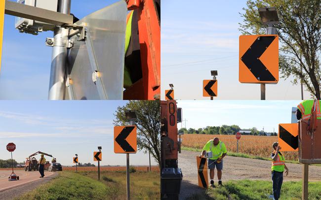
Figure 13. Photos. Installation of the SDCWS.
Technology Description
TAPCO's SDCWS utilizes Day-Viz™ LED enhanced solar powered signs and BlinkerBeam™ wireless controllers along with ultra-low power radar to detect and flash a series of chevron signs along with the advance warning sign in a horizontal curve. This system both warns and guides drivers through any upcoming horizontal curves.
The SDCWS is meant to replace existing W1-8 and advance warning signage or be used in the design of a new curve as a low-cost warning system. Chapter 2C of the Manual on Uniform Traffic Control Devices (MUTCD) and engineering judgment should be applied when determining appropriate sign layouts and locations.
Using the length and speed of the curve, the user can set each of the W1-8 chevron signs to flash in a specific sequence or time interval. Each curve design will have different sign placement and geometry for consideration when determining the appropriate flash sequence.
Typically, each sign will flash at least once per second according to MUTCD guidelines, with a minimum flash "ON" time of 100 milliseconds. When the quantity of chevrons exceeds nine, chevrons are commonly divided into two separate sequentially flashing systems in which the first and fifth sign will start flashing at the same time, followed by the second and sixth, and so on. This gives the effect of the system guiding or pulling the driver through the curve and highlights the geometry while still meeting the MUTCD guidelines.
The speed of the sequence and flash duration are determined based on the quantity of signs and speed of the curve. For example, when the speed of the curve is 45 mph and the curve distance from the start of the advance warning sign to the last chevron is 1,000 ft, the flash duration can be set to 15 seconds (1,000 ft , 66 ft/sec = 15 seconds). This time will vary based on existing sign locations, driver speed, and other factors noticed during installation.
The radar can detect up to 300 ft in advance of the curve sign and will commonly be set to flash at or just below the advisory speed of the curve. Once this speed threshold is exceeded, the radar will trigger the flash of the advance warning sign and sequential chevron signs using TAPCO's 900-Mhz BlinkerBeam™ wireless network. This wireless network is constantly communicating with each sign and providing a synchronization pulse throughout the network. This synchronization pulse is what each sign controller will use to keep the proper flash time and sequence.
During setup, the user can program when the sign LEDs should turn on (called "Beacon Start") and the duration they should stay on (called "Beacon Stop"). The Beacon Stop will become the duty cycle, which is typically no less than 100 milliseconds. This allows many options for configuring the flash sequence and speed of the flash for each horizontal curve. The system in its entirety can be seen in figure 14.
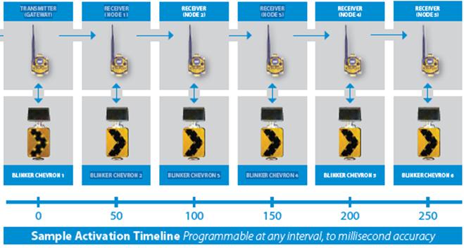
Figure 14. Photo. SDCWS activation sequence.