| << Previous | Contents | Next >> |
Full-Depth Repairs
3.0 Design Considerations
Full-depth repairs that are properly designed and constructed will provide good long-term performance for as long as the surrounding concrete pavement. The overall condition of the pavement and the extent of deterioration should be carefully examined to ensure that the placement of full-depth repairs will perform as intended. The following are important design considerations:
- Pavement type (jointed or continuously reinforced)
- Patch size (for distress and subgrade conditions)
- Load transfer (dowels versus other methods).
- Causes of failure
3.1 Pavement Type
Jointed concrete pavements (JCP)
Jointed concrete pavements typically require far more repairs at joints than between joints. Some pavements develop mid-panel cracks that deteriorate under repeated heavy traffic loading. Locking of the doweled joints will accelerated this crack deterioration by forcing open the mid-panel cracks. These cracks soon lose their aggregate interlock under repeated heavy traffic loadings. Some pavements may have joints with very little deterioration but one or more mid-panel cracks in each slab opened wide and essentially acting as joints. The types of JCP distresses that can be successfully addressed through full-depth repairs are described in Table 1.
Continuously Reinforced Concrete Pavements (CRCP)
Most full-depth repairs on CRCP will be placed at the areas exhibiting punchouts and other localized distresses. Full-depth repairs may also be required at medium and high severity transverse cracks in which the steel has ruptured. The type of CRCP distresses that can be addressed through full-depth repairs are listed in Table 1.
3.2 Patch Size
It is important that the boundaries be located so that all significant distresses are removed. Deterioration near joints and cracks may be greater at the bottom of the slab than at the top of the slab. Therefore, further investigation should be performed. Special attention should be paid to distress caused by "D" cracking because of the difficulty in determining their extent beneath the surface of the slab. It is advantageous to set the repair boundaries to go beyond the limits of any subbase voids created from the erosion action of pumping. In freeze-thaw climates below-slab deterioration may extend up to 1 m (3 ft) beyond visible surface distress.
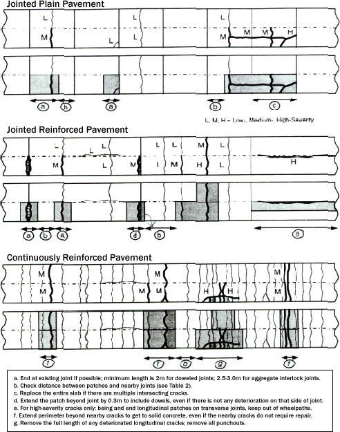
Figure 4. Repairs recommendation for various distresses

The location of patch boundaries also depends on the level of load transfer which is to be provided. The patches must be of sufficient size to eliminate rocking and longitudinal cracking of the patch. A minimum patch length of 1.8m (6 ft) and full-lane patch width of 3.6m (12 ft) is recommended to provide stability and to prevent longitudinal cracking. For the same reason, the minimum remainder of the slab must be at least 1.8m (6 ft).
For CRCP, the patch boundary should not be too close to an existing transverse crack, or distress will occur between the patch joints and the transverse crack. Generally, the patch should not be closer than 18 inches to an existing transverse crack. It may be necessary to extend the size of patches beyond the minimum length when making the pavement removal areas just before construction.
Figure 4 provides examples on how to define patch areas for various distresses on both jointed and continuously reinforced concrete pavements.
Combining two smaller patches into one large patch often can reduce repair cost. When two patches will be closer than the distances as shown in Table 2, it is probably more cost-effective to combine them into on large patch. However, the longest patch length should not exceed the pavement's longest slab length.
| Slab Thickness mm (in) | PATCH (LANE) WIDTH m (ft) | |||
|---|---|---|---|---|
| 2.7 (9) | 3.0 (10) | 3.3 (11) | 3.6(12) | |
| 175 (7) | 5.2 (17) | 4.6 (15) | 4.3 (14) | 4.0 (13) |
| 200 (8) | 4.6 (16) | 4.0 (13) | 3.7 (12) | 3.4 (11) |
| 225 (9) | 4.0 (13) | 3.7 (12) | 3.4 (11) | 3.0 (10) |
| 250 (10) | 3.7 (12) | 3.4 (11) | 3.0 (10) | 2.7 (9) |
| 275 (11) | 3.4 (11) | 3.0 (10) | 2.7 (9) | 2.4 (8) |
| 300 (12) | 3.0 (10) | 2.7 (9) | 2.4 (8) | 2.4 (8) |
| 375 (15) | 2.4 (8) | 2.4 (8) | 2.1 (7) | 2.0 (6) |
3.3 Load Transfer
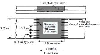
Jointed Pavements - For most full-depth repairs of jointed pavements, except for light traffic plain pavements, doweled transverse joints are essential for load transfer. The design of the retrofit dowel layouts includes the number of devices, diameter, and spacing of the dowel bars. Factors such as large diameter dowel bars and dowel bars spaced closely together will serve to reduce the bearing stresses of the dowels on the concrete. Lower dowel bearing stress reduces the development of dowel looseness, which reduces the potential for faulting. One study determined that stresses and deflections for a joint with 6 dowels (3 in each wheelpath) were similar to stresses and deflections for a joint with 12 uniformly spaced dowels. [2] For interstate-type pavements, at least four to five dowels should be located in the wheel path to provide effective load transfer (Figure 5). The use of 38 mm (1.5 inches) diameter dowels is recommended because they provide the most cost effective load transfer capacity. It is expected that concentrating retrofitted dowels in the wheelpath should provide adequate performance for the shorter service life expected from a rehabilitated pavement.
Figure 5. Recommend dowel bar design for interstate-type pavements

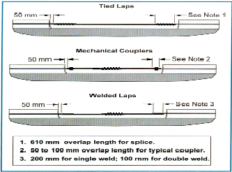
 Figure 6. Steel splice techniques for CRCP |
Continuously Reinforced Pavements - For full-depth patching in continuously reinforced pavements, new steel bars are necessary to maintain the continuity of the reinforcing bars that run longitudinally through the pavement. The reinforcing bars provide load transfer at the closely spaced cracks by keeping the cracks from opening. Reliable methods to attach the new bars to the salvaged lengths of the old bars include tied splices, mechanical fastened splices and welded splices. The bars should rest on supporting chairs if the patch is longer than 1.25 m (4 ft) to avoid bending, sagging or stressing the splices. Compared with tied splices, mechanical couples do not require as much old steel exposure. Most mechanical couples require about 25-50 mm (1-2 in) overlap. A single 6 mm (0.25 in) weld requires 200 mm (8 in) lap length, and a double weld requires 100 mm (4 in) lap length. To avoid buckling, it is better to weld a separate new bar to each exposed old bar, then use a tied splice to connect the new bars near the center of the patch. Figure 6 shows the steel splice techniques for continuously reinforced concrete pavements.
To save construction time, some agencies avoid splicing to the old steel by drilling holes and anchoring all new reinforcing bars into the old concrete. This procedure makes the repair faster because it does not require any hand chipping to expose the lap length of existing reinforcing bars. Holes for reinforcing bars are drilled into the transverse faces to the depth specified for a wire-tied overlap.
| << Previous | Contents | Next >> |

