U.S. Department of Transportation
Federal Highway Administration
1200 New Jersey Avenue, SE
Washington, DC 20590
202-366-4000
Federal Highway Administration Research and Technology
Coordinating, Developing, and Delivering Highway Transportation Innovations
| REPORT |
| This report is an archived publication and may contain dated technical, contact, and link information |
|
| Publication Number: FHWA-HRT-16-009 Date: March 2017 |
Publication Number: FHWA-HRT-16-009 Date: March 2017 |
As described in previous chapters, pavement deflection data can be used to determine material properties of pavement layers and the subgrade. In this process, known as “backcalculation,” pavement layer stiffnesses are determined based on the deflection data and the assumed pavement cross section. Over the years, the evaluation of pavement deflection data has become increasingly more complex, driven largely by the interest in moving toward more mechanistic pavement analyses and the increasing power of today’s sophisticated computers. Many different concepts and approaches are available to perform backcalculation of deflection data, which vary primarily by the type of pavement being analyzed.
This chapter presents an overview of backcalculation concepts for flexible, rigid, and composite pavements, as well as other uses of deflection data. Chapters 4 through 6 discuss FWD data analysis and interpretation for the three pavement types, respectively, in more detail.
The most widely used technique of determining the effective elastic moduli of the pavement structural layers and subgrade is backcalculation of elastic moduli based on measured surface deflections. The process can be described using the case of a simply supported beam, as depicted in figure 29.(28)
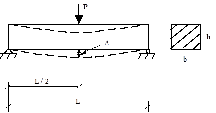
©National Highway Institute
P = Load.
b = Width.
L = Length.
h = Height.
Δ = Maximum deflection.
Figure 29. Diagram. Simply supported beam with a concentrated midspan.(28)
From fundamental engineering mechanics, the maximum deflection occurs under the load (i.e.,in the middle of the beam) and is calculated in figure 30.

Figure 30. Equation. Maximum deflection of a beam under a fixed load.
Where:
Δ = Midspan deflection of the beam.
P = Load applied to the surface.
L = Beam span.
E = Elastic modulus of the beam.
I = Moment of inertia for a rectangular beam.
The moment of inertia for a rectangular beam I can be determined from the width and height of the beam, as shown in figure 31.

Figure 31. Equation. Moment of inertia of rectangular beam.
Where:
b = Beam width.
h = Beam height.
Finally, the elastic modulus of the beam (E) can be calculated by substituting the known values of P, L, b, and h.
Although similar in concept to the beam example just described, the process of backcalculating the elastic moduli for pavements is more complicated because multiple unknowns (i.e., the moduli of the various pavement layers and their interaction with one another) affect the total deflection measured on the surface. Over the years, researchers and practitioners have developed numerous approaches to backcalculate pavement layer and subgrade moduli as well as numerous programs to perform the calculations. Table 1 summarizes some of the available software programs that can be used for backcalculation of deflection data, along with the forward and backcalculation schemes and other characteristics of the programs. In the next sections of this chapter, methods for backcalculating individual layer moduli for flexible, rigid, and composite pavements are described, including a discussion of some of these programs, where appropriate.
Table 1. Summary of available backcalculation programs.
| Program Name |
Latest Version |
Developer | Public Domain |
Pavement Type |
Forward Calculation Method |
Forward Calculation Subroutine |
Backcalculation Method |
Nonlinear Analysis |
Layer Interface Analysis |
Maximum Number of Layers |
Seed Moduli |
Range of Acceptable Modulus |
Ability to Fix Modulus |
Convergence Scheme |
Error Weighting Function |
|---|---|---|---|---|---|---|---|---|---|---|---|---|---|---|---|
| BAKFAA | N/A | Federal Aviation Administration (FAA) | Yes | Rigid/ Flexible | Multilayer Elastic Theory | LEAF | Iterative | No | Variable | 5 | Required | Required | Yes | Sum of squares of absolute error | Yes |
| BISDEF© | N/A | USACE-WES | No | Flexible | Multilayer Elastic Theory | BISAR | Iterative | No | Variable | Number of deflections; best for 3 unknowns | Required | Required | Yes | Sum of squares of absolute error | Yes |
| BOUSDEF | 2.0 | Zhou et al. (Oregon State) | No | Flexible | Equivalent Thickness | MET | Iterative | Yes | Fixed (rough) | At least 4 | Required | Required | NA | Sum of percent errors | N/A |
| CHEVDEF | N/A | USACE-WES | Yes | Flexible | Multilayer Elastic Theory | CHEVRON | Iterative | No | Fixed (rough) | Number of deflections; best for 3 unknowns | Required | Required | Yes | Sum of squares of absolute error | Yes |
| COMDEF | N/A | USACE-WES | No | Composite | Multilayer Elastic Theory | BISAR | Database | No | Fixed (rough) | 3 | No | No | N/A | Various | No |
| DBCONPAS | N/A | Tia et al. (University of Florida) | No | Rigid | Finite Element | FEACONS III | Database | Yes | N/A | 2 | No | No | N/A | N/A | N/A |
| DIPLOBACK | N/A | Khazanovich and Roesler | No | Composite | Multilayer Elastic +Westergaard |
Neural Networks | Closed Form Solution | No | N/A | 3 | No | No | No | Closed form solution | N/A |
| ELMOD®/ ELCON | 5 | Ullidtz (Dynatest®) | No | Flexible/ Rigid | Equivalent Thickness/ Finite Element | MET | Iterative | Yes (subgrade only) | Fixed (rough) | 4 (exclusive of rigid layer) | No | No | Yes | Relative error of 5 sensors | No |
| ELSDEF | N/A | Texas A&M, USACE-WES | No | N/A | Multilayer Elastic Theory | ELSYM5 | Iterative | No | Fixed (rough) | Number of deflections; best for 3 unknowns | Required | Required | Yes | Sum of squares of absolute error | Yes |
| EMOD | N/A | PCS/Law | No | N/A | Multilayer Elastic Theory | CHEVRON | Iterative | Yes (subgrade only) | Fixed (rough) | 3 | Required | Required | Yes | Sum of relative squared error | No |
| EVERCALC© | 5.0 | Mahoney et al. | Yes | Flexible | Multilayer Elastic Theory | WESLEA | Optimization | Yes | Fixed (rough) | 4 (exclusive of rigid layer) | Required if more than 3 layers | Required | Yes | Sum of absolute error | Yes |
| FPEDD1 | NA | Uddin | No | NA | Multilayer Elastic Theory | BASINF | Iterative | Yes | Fixed (rough) | NA | Program Generated | NA | NA | NA | No |
| ILLI-BACK | NA | Ioannides | No | Rigid and Composite | Closed Form Solution | Closed Form Solution | Closed Form Solution | No | No | 2 | No | No | No | Closed form solution | NA |
| ISSEM4 | NA | Ullidtz, Stubstad | No | NA | Multilayer Elastic Theory | ELSYM5 | Iterative | Yes (finite cylinder concept) | Fixed (rough) | 4 | Required | Required | Yes | Relative deflection error | No |
| MICHBACK© | NA | Harichandran/ Michigan State | Yes | Flexible/ Composite | Multilayer Elastic Theory | CHEVRONX | Raphson-Newton Method | No | NA | 3 + rigid layer | Required | Required | Yes | Least squares | Yes |
| MODCOMP© | 6 | Irwin, Szebenyi | Yes | Flexible | Multilayer Elastic Theory | CHEVRON | Iterative | Yes | Fixed (rough) | 2 to 15 layers; maximum of 5 unknown layers |
Required | Required | Yes | Relative deflection error at sensors | No |
| MODULUS | 6.0 | Texas Transportation Institute | Yes | Flexible | Multilayer Elastic Theory | WESLEA | Database (Optimization) | No | Fixed | 4 plus rigid layer | Required | Required | Yes | Sum of relative squared error | Yes |
| PADAL | 2 | Brown et al. | No | NA | Multilayer Elastic Theory | NA | Iterative | Yes (subgrade only) | Fixed | NA | Required | NA | NA | Sum of relative squared error | NA |
| PCASE | 2.08 | USACE | Yes | Rigid/ Flexible/ Composite | Multilayer Elastic Theory | LEEP/ WESLEA | Iterative | No | Variable | 5 | Required | Required | Yes | Sum of squares of absolute error | Yes |
| RPEDD1 | NA | Uddin | No | Rigid | Multilayer Elastic Theory | BASINR | Iterative | Yes | Fixed? | NA | Program Generated | NA | NA | NA | No |
| WESDEF | NA | USACE-WES | Yes | Flexible | Multilayer Elastic Theory | WESLEA | Iterative | No | Variable | 4 + rigid layer | Required | Required | Yes | Sum of squares of absolute error | Yes |
NA = Not applicable.
USACE-WES = U.S. Army Corps of Engineers—Waterways Experiment Station.
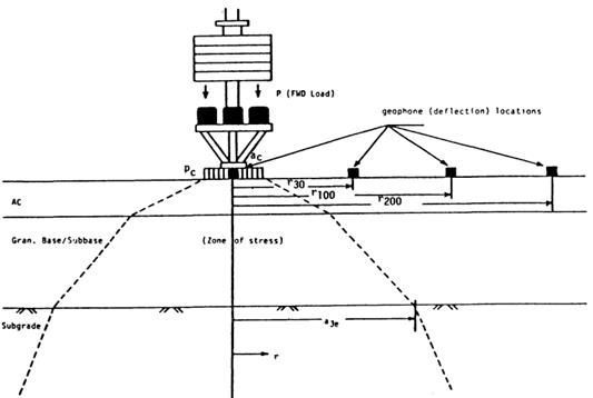
To help explain the concept of backcalculation for flexible pavements, consider figure 32, which shows a three-layer system with the surface deflections measured by sensors at five locations. The load is arbitrarily assumed to be distributed through the pavement layers according to the broken lines.(29) In this example, the deflections measured by sensors 4 and 5, which are located outside the stress zone of the HMA and base layers, depend solely on the subgrade. As a first step, any reasonable moduli can be assumed for the HMA and granular base, while the subgrade modulus is varied until the computed deflections at sensors 4 and 5 match measured deflections. Next, the deflection at sensor 3 depends on the moduli of the granular base and the subgrade, which is determined in the first step and is independent of the HMA modulus. Thus, the modulus of the granular base is varied until a satisfactory match between the computed and measured deflection at sensor 3 is obtained. Finally, the modulus of the HMA layer is determined by applying the same procedure to sensors 1 and 2.(29)
One limitation of this procedure is the assumption of the linear response of the pavement layers to the load. The problem is more complicated if the granular base and subgrade behave in a nonlinear fashion. Theoretically, to match the deflection at a given sensor, the stress points for computing the elastic moduli of all nonlinear layers should be located directly beneath that sensor. The use of different stress points for different sensors is not possible because elastic layer theory limits only one stress point in each layer. The best approach is to assume an average stress distribution with the stress points shown by the smaller circles in figure 32.(32) Other issues that complicate the analysis include a dynamic (instead of static) response, the effect of underlying bedrock layers, and the effect of temperature and moisture fluctuations.
©AASHTO
P = Applied load.
Pc = Contact pressure.
ac = Contact area.
r30 = Distance of second geophone from load center.
r100 = Distance of third geophone from load center.
r200 = Distance of fourth geophone from load center.
a3c = Radial distance in which stress zone intersects interface of subbase and subgrade layers.
Figure 32. Diagram. Stress zone under the FWD load.(32)
Many of the backcalculation approaches (and corresponding programs) for flexible pavements are similar, although the results obtained from the programs do differ because of the inherent assumptions, iteration techniques, and forward and backcalculation schemes built into the programs. The following sections briefly describe the various approaches used for backcalculation of flexible pavements.
Several researchers have developed regression equations for predicting layer moduli from the deflection testing data. For example, Newcomb developed regression equations for two- and three-layer pavement systems to predict the subgrade modulus as part of an overall effort to develop a mechanistic-empirical overlay design procedure for the Wisconsin Department of Transportation.(30) Horak also developed a regression equation to predict the subgrade modulus using the deflection at 2,000 mm (79 inches) from the center of the load plate.(31)
The most commonly used equation for predicting the subgrade modulus is presented in the 1993 AASHTO Design Guide and shown in figure 33.(32)

Figure 33. Equation. Backcalculation of subgrade modulus.(32)
Where:
MR = Backcalculated subgrade resilient modulus, MPa (lbf/inch2).
P = Applied load, kN (lbf).
dr = Measured deflection at distance r from applied load, mm (inches).
r = Radial distance at which the deflection is measured, mm (inches).
The guide also presents equations to ensure that the deflection used in this equation is sufficiently far away from the load so that the deflection is primarily due to deformation of the subgrade, yet as close as possible to minimize errors associated with smaller deflections.
The guide also presents an equation, shown in figure 34, for predicting the effective modulus of the pavement structure (i.e., all layers above the subgrade).(32)
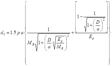
Figure 34. Equation. Computation of the effective modulus of the pavement structure.(32)
Where:
d0 = Deflection measured under plate and adjusted to standard temperature, mm (inches).
p = FWD load plate pressure, MPa (lbf/inch2).
a = FWD load plate area, mm2 (inches2).
D = Total thickness of pavement layers above the subgrade, mm (inches).
MR = Subgrade resilient modulus, MPa (lbf/inch2).
Ep = Effective modulus of all pavement layers above the subgrade, MPa (lbf/inch2).
MET is based on Odemark’s assumption, which is that the deflections of a multilayered pavement system with moduli Ei and layer thicknesses hi can be obtained using a single layer of thickness H and modulus E provided that H satisfies the equation shown in figure 35 where C equals the layer coeifficent.(33)

Figure 35. Equation. Methodology for computing equivalent thickness.(33)
Ullidtz reports that this method produces results that are as good as or better than those obtained from layered elastic and finite element solutions, when compared with measured data.(33,34) The method can also be adapted to handle nonlinear subgrade materials. Another advantage of this method is its simplicity, which leads to significant savings in computation time.
ELMOD3 is an example of a program that uses the Odemark-Boussinesq method of equivalent layer thickness concept and the radius of curvature method.(33) Initially, the subgrade material properties, stiffness and nonlinearity, are calculated using the deflections from the outer sensors. The radius of curvature from the central sensors can be used to assess the stiffness of the upper pavement layer. The stiffness of the remaining layers is then calculated based on the overall pavement response to the applied load. This ensures that the proposed pavement structure results in the correct central deflection under the measured load.
The surface modulus concept is very useful for estimating subgrade modulus and for diagnosing stress-sensitive subgrade material and the presence of stiff layers. It uses Boussinesq’s original closed-form equations relating the vertical deflection on the surface of a homogeneous, isotropic, linearly elastic halfspace δz and the elastic modulus E (figure 36 and figure 37).

Figure 36. Equation. Vertical deflection under a uniformly distributed load.

Figure 37. Equation. Vertical deflection under a point load.
Where:
P = Surface load, kN (lbf).
r = Radial distance from center of load, mm (inches).
a = Radius of loaded area, mm (inches).
μ = Poisson’s ratio.
These equations can be used directly to backcalculate the surface modulus E0, given a measured surface deflection due to a known load. For a multilayered pavement system, the calculated surface modulus at the center tends to underestimate the modulus of the surface layer and overestimate the modulus of the subgrade.(35) However, the surface modulus approaches a constant value at large radii; this value corresponds to the subgrade modulus, illustrating a basic principle of backcalculation, which is that the outer deflections can be used to determine the moduli of the deeper layers. If the surface modulus increases with increasing radial distance, then it is an indication of a stress-sensitive (nonlinear) subgrade or the presence of a stiff layer.(33)
BOUSDEF is another program that uses the MET. This program assumes a single, uniform layer of material and uses Boussinesq’s equations to determine theoretical deflections. By matching the deflection basins measured in the field, the program calculates the moduli of the surface, base, and subgrade layer.
In this method (sometimes referred to as a “basin search method”), a forward calculation program is used to generate a database of deflection basins for different combinations of layer moduli, specified layer thicknesses, material properties, pavement types, and loading conditions. The measured deflection basin is compared with the deflection basins in the database using a search algorithm, and a set of moduli are interpolated from the layer moduli that produces the closest calculated deflection basins in the database.
The MODULUS backcalculation program, which uses databases generated by the WESLEA program, is one program that uses this approach.(36,37) The number of basins required to obtain a suitable database depends on the number of layers and the expected moduli ranges provided by the user (i.e., wide ranges require generation of a greater number of basins than narrow ones). The generated deflection basins are then searched using an algorithm, and the moduli are interpolated using the various deflection basins. The program optimizes the solution by seeking to minimize the relative sum of squared differences between the measured and calculated surface deflections. The program always converges, although the chances of converging to a local minimum cannot be ruled out.(38) The program performs a convexity test to determine the likelihood of having converged to a local minimum, and the user is warned if this test is not satisfied.
WESDEF is another example of a backcalculation program that uses this approach. This program was developed at the USACE-WES. It is capable of handling up to five layers (the bottom layer is “fixed” to act as a rigid layer), although one study showed that reasonable results are obtained if the number of backcalculated layers is kept to three.(39)
This type of approach is best suited for cases when a large number of pavements with a similar configuration need to be tested in succession. For these situations, the generated database can be used repeatedly to backcalculate the pavement layer moduli for all similar pavements, and the time required to generate the database can be minimized. This technique can be used with a database generated from any linear or nonlinear program.(38)
The iterative method is another approach used in the backcalculation of flexible pavements. In this approach, layer moduli are repeatedly changed until the calculated deflection basin matches the measured deflection basin within a specified tolerance. The primary problem associated with backcalculating elastic moduli for a layered pavement structure is that the equations for calculating pavement surface deflection are not closed-form solutions (i.e., the unknowns cannot be solved directly). Therefore, a rigorous iterative process involving some decision and convergence criteria is required. Figure 38 illustrates how this process works.
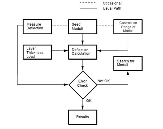
©Washington State Department of Transportation (after Lytton)
Figure 38. Chart. Typical iterative backcalculation flow.(40,41)
The search algorithm is usually achieved by minimizing an objective function of any set of independent variables (i.e., layer moduli, thicknesses, etc.), which is commonly defined as the weighted sum of squares of the differences between calculated and measured surface deflections as shown in figure 39.

Figure 39. Equation. Objective function to be minimized in the search algorithm used in iterative method.
Where:
wjm = Measured deflection at sensor j, mm (inches).
wjc= Calculated deflection at sensor j, mm (inches).
aj= Weighing factor for sensor j, mm (inches).
This equation can be solved using nonlinear optimization methods, which locate the least value of the objective function. Many minimization techniques are available in the literature, including the factored secant update method, modified Levenberg-Marquardt algorithm, and modified Powell hybrid algorithm.(42) One issue with this approach is that the program result may converge to different solutions for different sets of seed moduli. Another issue is that the convergence can be very slow, requiring numerous iterations of the forward calculation program.
An example of an iterative program is EVERCALC©, which uses the Levenberg-Marquardt minimization algorithm.(43) The program seeks to minimize an objective function formed as the sum of squared relative differences between the calculated and measured surface deflections. EVERCALC© is a robust, efficient, and accurate program, and uses the CHEVRON computer program for forward calculations.
CHEVDEF is another example of a backcalculation program that uses the CHEVRON program for forward calculations.(44) This program uses an assumed linear variation in logarithmic space between layer moduli and surface deflections to revise the layer moduli after each iteration. It employs a gradient search technique, and the correct set of moduli is searched in an iterative manner. As previously described, one issue with programs that use this approach is they are highly dependent on the initial seed moduli and can provide different solutions for different initial seed moduli.
MODCOMP© is another program that uses an iterative method. MODCOMP4 was selected as the recommended program to calculate the elastic moduli of the pavement layers and subgrade for the LTPP test sections, considering the following factors:(23)
Accuracy of the program.
Operational characteristics.
Ease of use of the program.
Stability of the program.
Probability of success.
MODCOMP4 was found to result in a reasonable solution in more than 90 percent of the initial study sections.(23) This program uses a nonlinear constitutive equation to represent the response of unbound pavement materials and soils, while also offering the use of linear elastic response models to estimate the nonlinear properties. It also converges reasonably fast and can be used in batch mode to analyze numerous deflection basins. The study also found that the root mean square (RMS) error for each solution varied between 0.1 and 1 percent, which was considered acceptable.(23)
MICHBACK© is yet another example of an iterative backcalculation program. It uses the CHEVRONX computer program for forward calculations and the modified Newton-Raphson (also called “secant”) method for minimization. The method of least-squares is used to solve the over-determined system of equations (m equations in n unknowns, m > n). If desired, weighting factors can be used for each sensor measurement to emphasize some deflection measurements over others.
The previous approaches consider the load applied to the pavement surface to be a static load. Computationally, this approach is very efficient, and when the depths of the layers are known and their properties are largely homogeneous with depth, the procedure is effective in backcalculating layer properties. However, when the depths are uncertain or when the moduli vary within a layer, the static backcalculation scheme may not yield reliable results. Moreover, impulse-loading devices, such as the FWD, impart a dynamic load to the pavement.
To overcome the limitation of static deflection analysis, extensive recent work has been conducted to interpret the dynamic response of FWD deflection time histories. To model the dynamic deflections in pavement layers, the vertical profile is discretized into a number of thin computational layers, and the moduli of these layers are used as variables in an optimization problem that seeks to minimize the residual error between computed and observed deflections over time. The solution is obtained by gradient-based numerical methods that require the repeated evaluation of the error (objective) function and its derivatives, which is also known as a “forward solution.” The objective function to be minimized is the difference between the recorded response at the FWD sensors and the computed response of a pavement profile whose properties are encoded in the vector x. This represents the error in the model, and the minimization problem may be written as shown in figure 40.(45)

Figure 40. Equation. Algorithm for minimization of the difference between FWD response and computed response.(45)
Where:
n = Number of computational layers.
nr = Number of receivers.
nt = Number of time steps in the recorded response.
frec = Recorded motion.
fcom = Computed motion.
The forward solution is the most computationally extensive and time-consuming portion of the computation. Various backcalculation computer programs available at the time of this report employ various methods to accelerate this computation. These programs include EVERCALC© (developed by the Washington State Department of Transportation), MICHBACK© (developed by Michigan Department of Transportation), and DYNABACK-F.
The DYNABACK-F program uses new algorithms for backcalculating layer parameters based on dynamic interpretation of FWD deflection time histories using frequency and time-domain solutions. The backcalculation procedure is based on the modified Newton-Raphson method originally adopted in the MICHBACK© program. Singular value decomposition (SVD), in conjunction with scaling and truncation techniques, is employed in solving for the inverse problem. The frequency-domain method uses real and imaginary deflection basins as the measured quantities, while the time-domain method uses either the peak deflections and corresponding time lags or traces of the deflection time histories as the measured quantities to be matched by the backcalculation procedure.(46)
The results indicated that dynamic backcalculation of layer parameters using field data would present some challenges. The frequency-domain method can lead to large errors if the measured FWD records are truncated before the motions fully decay in time. The time-domain methods, when simultaneously backcalculating layer moduli and thicknesses, produce mixed results. Convergence is not ensured when using peak deflections and corresponding time lags. However, when matching traces of sensor time histories, the SVD method allows very good convergence and the backcalculation of the HMA layer thickness, in addition to the layer moduli and damping, even when using field-measured data.(46)
As noted previously, the static analysis of deflection data can produce great errors, while the dynamic analysis using gradient search optimization procedures is very time consuming. To overcome limitations of both methods, ANN technologies can be applied to the backcalculation problem. DIPLOBACK is an example of a program that uses this approach.
ANNs are biologically inspired analogies of the human brain. They are composed of many operationally simple yet highly interconnected units. Similar to a human brain, certain types of ANNs can “teach themselves” to recognize common features within the data and to group the data accordingly through repeated exposure to a set of data.(47) ANNs can also generalize an ideal mapping from imperfect examples and extract essential information from input containing both relevant and irrelevant data. Their ability to “see” through noise and distortion to the underlying pattern has been exploited successfully for solving many problems related to pattern recognition.(47)
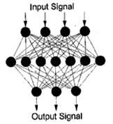
To solve the backcalculation problem as a pattern recognition task, multilayer, feed-forward ANNs are used (see figure 41). The interconnected units pass information in the form of signal patterns. The output signal patterns from a given input signal pattern are uniquely determined by the distribution of connection strengths throughout the network.
©National Academy of Sciences.
Reproduced with permission of the
TRB
Figure 41. Diagram. ANN architecture.(47)
The excitation level of a processing element is modeled mathematically as a weighted sum of inputs from the neighboring elements, as shown in figure 42.(47)

Figure 42. Equation. Excitation level of a processing element.(47)
Where:
Nj= Excitation level.
wji = Weight assigned to the connection.
xi = Signal coming from the ith processing element in the preceding layer.
The response of a processing element to the net excitation Nj is modeled by the logistic function in figure 43.(47)

Figure 43. Equation. Response of a processing element to the net excitation.(47)
Multilayered, feed-forward ANNs are commonly trained by a technique known as “error backpropagation.” After each training example is presented to the network, the errors (i.e.,differences between the calculated and target output patterns) are computed and propagated backward through the network.
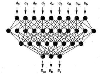
Meier and Rix trained backpropagation networks to backcalculate HMA pavement layer moduli from deflection basins obtained using an FWD.(47) A three-layer pavement system consisting of an HMA layer, nonstabilized base, and subgrade was considered. Figure 44 illustrates the network architecture chosen to determine the layer moduli for the measured deflection basin and known HMA and base layer thicknesses.
©National Academy of Sciences. Reproduced with
permission of the TRB
Figure 44. Diagram. ANN for backcalculating pavement moduli.(47)
The primary advantage of an ANN is that it is an accelerated backcalculation process. In addition, the ANN analysis does not require seed moduli and ranges, which means the backcalculation process is less dependent on user subjectivity. However, the applicability of the ANN is limited by the range of pavement layer properties that are included in the training process. In addition, increasing the number of layers to be analyzed increase the computation time.
Gucunski, Abdallah, and Nazarian recently developed an ANN for backcalculation of pavement profiles from data obtained from the Surface Analysis of Spectral Waves test.(48) They reported a significant improvement in accuracy of evaluation of pavement properties in comparison with previous ANN models. The improvement was primarily attributed to the use of a data transformation algorithm that generates smoother and more linear relations, thus enabling a better learning process.(48)
As previously mentioned, the deflections measured on a PCC slab are used for backcalculating the PCC elastic modulus and k-value of the supporting medium. The PCC elastic modulus can be used to evaluate the structural condition of the PCC slab, while the k-value can be used to evaluate supporting layers. Those two parameters are required inputs for both new and overlay design procedures using the new MEPDG.(7)
Traditionally, there are two basic approaches for backcalculation of pavement layer moduli and subgrade support conditions. One approach is based on layered elastic theory. This approach is commonly used for analysis of flexible pavements and has already been described in this chapter. The second approach was developed specifically for rigid pavements and is based on plate theory. With this approach, the pavement structure can be modeled as either a slab on an elastic solid foundation or on a dense liquid foundation. The plate theory approach can be based on either the AREA or Best-Fit method, both of which are briefly described in the following sections (and more thoroughly presented in chapter 5). Both methods are based on Westergaard’s solution for an interior loading of a linear elastic, homogeneous, isotropic plate resting on a dense liquid foundation.
For backcalculation, rigid pavements are generally treated as two-layer systems because the base or subbase has little influence on the shape of the deflection basin compared with the influence of the PCC and subgrade.(14) Those systems are modeled as a rigid plate resting on an elastic solid or a dense liquid foundation. Such a configuration allows obtaining the closed-form solution based on the dimensional analysis of the deflection basin, which involves the AREA parameter and the radius of relative stiffness ℓ (49). The procedure consists of the following steps:
Step 1: Drop the weight and record the applied load (P) and the resulting deflections.
Step 2: Calculate the normalized area of the basin (AREA).
Step 3: Determine the radius of relative stiffness (ℓ).
Step 4: Backcalculate subgrade support (k or C for dense liquid or elastic solid foundation, respectively).
Step 5: Backcalculate the slab flexural stiffness (D), define the slab modulus of elasticity (E) if the slab thickness (h) is known, or, alternatively, define h if E is known.
The computational steps of the procedure above are described in more detail in following sections and are further illustrated in chapter 5.
AREA Parameter
The use of a parameter AREA was first proposed by Hoffman and Thompson for interpreting flexible pavement deflection basins.(50) This parameter combines the effect of several measured deflections in the basin, defined as shown in figure 45.(27)

Figure 45. Equation. Parameter AREA.(27)
Where:
Wi= Measured deflections (i = 0, n–1), mm (inches).The AREA algorithm has been used extensively to analyze PCC pavement deflection basins. Ioannides, Barenberg, and Lary identified the unique relationship between AREA and the radius of relative stiffness, and Hall et al. obtained simple approximations for this relationship for different sensor configurations.(49,51) This approach is used for rehabilitation design of rigid pavements in the 1993 AASHTO Design Guide.(32)
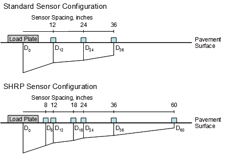
The AREA parameter represents the normalized area of a slice taken through the deflection basin between the center of the load plate and an outer sensor.(14) Several methods of computing AREA are available, including, for PCC pavements, one using a standard sensor configuration and one using the Strategic Highway Research Program (SHRP) sensor configuration (see figure 46).
1 inch = 25.4 mm.
Figure 46. Diagram. Comparison of standard and SHRP sensor configurations for AREA computations.
Where:
dr = Deflection at radial distance r from the load center, mm (inches).
Using the trapezoidal rule, AREA is computed in figure 47 and figure 48 for the different configurations.

Figure 47. Equation. AREA via trapezoidal rule for standard sensor configuration.

Figure 48. Equation. AREA via trapezoidal rule for SHRP sensor configuration.
The standard formulation of AREA was used by Ioannides, Barenberg, and Lary to develop the procedure based on the AREA method.(49)
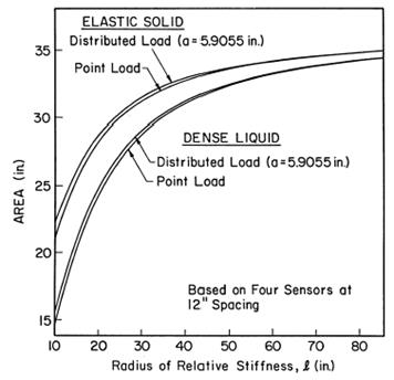
The AREA parameter provides a fairly good indication of relative stiffness of the pavement structure, particularly the bound layer(s), because it is largely insensitive to subgrade stiffness.(14) Ioannides, Barenberg, and Lary found a unique relationship between radius of relative stiffness and AREA, which is shown in figure 49.(49) A regression equation was also developed to define this relationship (see chapter 5).
©A.M. Ioannides
1 inch = 25.4 mm.
Figure 49. Graph. Variation in AREA with ℓ.(49)
For a dense liquid foundation, the radius of relative stiffness can be calculated as shown in
figure 50, assuming PCC and subgrade properties are known.(49)

Figure 50. Equation. Radius of relative stiffness for dense liquid foundation.
Where:
ℓ = Radius of relative stiffness, mm (inches).
E = PCC elastic modulus, MPa (lbf/inch2).
h = PCC thickness, mm (inches).
μ = PCC Poisson’s ratio.
k = Modulus of subgrade reaction (k-value), MPa/mm (lb/inch2/inch).
For an elastic solid foundation, the relationship shown in figure 51 exists.(49)
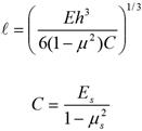
Figure 51. Equation. Radius of relative stiffness for elastic solid foundation.(49)
Where:
Es = Subgrade modulus of elasticity, MPa (lbf/inch2).
μs = Subgrade Poisson’s ratio.
According to Ioannides, Barenberg, and Lary, the k-value (for a dense liquid foundation) and C (for an elastic solid foundation) can be found knowing the load (P), radius of relative stiffness (ℓ), and measured deflections (dr), as shown in figure 52.(49)
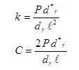
Figure 52. Equation. Estimation of subgrade support for dense liquid and elastic solid foundations.(49)
Where:
k = Modulus of subgrade reaction, MPa/mm (lbf/inch2).
C = Subgrade constant, MPa (lbf/inch2).
P = Applied load, N (lbf).
d*r = Nondimensional deflection coefficient for deflection at radial distance r from load.
dr = Measured deflection at radial distance r from the load, mm (inches).
ℓ = Radius of relative stiffness, mm (inches).
Knowing the subgrade constant (C) and Poisson’s ratio (μs), the subgrade modulus of elasticity (Es) can be backcalculated from the second part of the equation in figure 51.
If the slab thickness is known, the PCC elastic modulus can be backcalculated from equations in figure 50 or figure 51 for a dense liquid or elastic solid foundation, respectively. Alternatively, if the PCC elastic modulus is known, the slab thickness can be computed. The flexural stiffness of the slab (D) is defined in figure 53:

Figure 53. Equation. Flexural stiffness of the slab.
Using the radius of relative stiffness from the relationship in figure 53, figure 50 can be rearranged to solve for the PCC elastic modulus, as shown in figure 54.

Figure 54. Equation. Computation of the PCC elastic modulus for the dense liquid foundation.
Where:
EPCC = Elastic modulus of the slab, MPa (lbf/inch2).
ℓ = Radius of relative stiffness, mm (inches).
μ = PCC Poisson’s ratio.
k = Modulus of subgrade reaction, MPa/mm (lbf/inch2/inch).
h = Slab thickness, mm (inches).
The principles of backcalculation described here were used to develop the ILLI-BACK computer program. The method was validated with field data, and the coefficient of variation varied between 1 and 3 percent.(49) This closed-form solution can also be programmed into a spreadsheet format.
Another commonly used backcalculation procedure is the Best-Fit method. With this method, the PCC elastic modulus and subgrade k-value are found by identifying the best combination of the two parameters that produces a calculated deflection profile that best matches the measured profile.(51) This is performed through the minimization of the error function provided in
figure 55.

Figure 55. Equation. Minimization of the error function.
Where:
E = Elastic modulus of the slab, MPa (lbf/inch2).
k = Modulus of subgrade reaction, MPa/mm (lbf/inch²/inch).
αi = Weighting factors.
w(ri) = Calculated deflection at sensor location i, mm (inches).
Wi = Measured deflection at sensor location i, mm (inches).
The calculated deflection (wi) is based on Westergaard’s solution for the interior loading of a plate consisting of a linear elastic, homogenous, and isotropic material on a dense liquid foundation. The ability to control the weights given to the various deflection measurements adds some flexibility to the Best-Fit process.(27)
Through a series of assumed conditions and substitutions (described more fully in chapter 5), the equation in figure 56 can be used to determine the radius of relative stiffness.

Figure 56. Equation. Determination of radius of relative stiffness.
Where:
fi and f'i = Function of f, distance from the load, and parameters of applied load.
The radius of relative stiffness can then be used to determine the elastic modulus of the PCC slab using the equation in figure 54.
Likewise, for an elastic solid foundation, the PCC elastic modulus can be determined by the equation in figure 57.

Figure 57. Equation. Computation of the PCC elastic modulus for the elastic solid foundation.
Where:
EPCC = Elastic modulus of the PCC slab, MPa (lbf/inch2).
μPCC= PCC Poisson’s ratio.
ℓe = (D/C)1/3 = Radius of relative stiffness, mm (inches).
Es= Modulus of elasticity of the subgrade, MPa (lbf/inch2).
hPCC= PCC slab thickness, mm (inches).
μs= Poisson’s ratio of the subgrade.
A recent LTPP study compared results from the Best Fit and AREA methods of backcalculation for both dense liquid and elastic solid subgrade models.(27) Both the SHRP sensor configuration (seven sensors) and standard sensor configuration (four sensors spaced 305 mm (12 inches) apart) were also studied.
A critical assumption of plate theory is that there is no compression in the upper layer, such that the entire deflection is attributed to compression of the subgrade and bending of the plate. Khazanovich, Tayabji, and Darter observed a greater discrepancy between the Best-Fit and AREA methods when the deflection directly under the load was used in backcalculation.(27) At that location, the deflections predicted by plate theory and layered elastic theory differ the most because of compression in the PCC pavement. Therefore, it is reasonable to suggest that deviation of the PCC slab behavior from the plate theory prediction is a significant source of discrepancy between different backcalculation methods.(27) Further investigation using the DIPLOMAT program confirmed this discrepancy between the two methods. These findings, coupled with previous work performed by Hall et al., led the researchers to recommend the Best-Fit method for backcalculation of rigid pavements.(51) The Best-Fit method yields a lower coefficient of variation in backcalculated k-values from multiple drops, is less sensitive to the randomness in measured maximum deflections, and provides better correspondence between measured and calculated deflection basins. It is also able to provide the best fit between calculated and measured deflections for any sensor configuration.
Historically, the pavement is assumed to exhibit a quasi-static behavior. However, some evidence negates this assumption because there is a lag between the peak of the applied load and among the peaks of the sensor deflections. This dynamic behavior may explain the differences between laboratory and backcalculated moduli as well as between moduli obtained at different times of the year. Recently, researchers have been investigating the dynamic response and developing procedures and programs for dynamic backcalculation; these programs are evaluated as part of this study. However, these programs must be acceptable for routine use and should be able to efficiently analyze significant quantities of FWD data.
Khazanovich presented a closed-form solution to describe the dynamic behavior of a linear elastic, homogeneous, and isotropic plate on a dense-liquid foundation based on Westergaard’s solution for an interior loading.(52) The damping effects of the foundation are characterized by a damping parameter, and a dimensionless mass parameter is used to adjust the dynamic pavement response as a result of the effects of the inertia of the pavement. A backcalculation procedure can be developed based on this solution.
Likewise, Chatti and Kim developed the DYNABACK-R program for backcalculation of the dynamic subgrade stiffness and damping coefficients from the FWD deflection basin.(53) The program can also be used to detect a stiff layer beneath the pavement system.
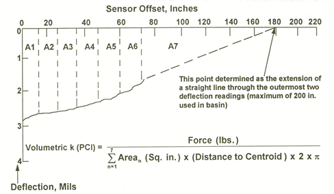
To accomplish this effort, the transient deflection signal of each FWD sensor was first decomposed into a series of harmonic motions by the fast Fourier transform (FFT) algorithm. Then, for each frequency of interest, the real and imaginary components of the displaced volume underneath the slab were calculated from the complex deflection basin. The dynamic force-displacement relationship were decomposed into real and imaginary parts, leading to a simple system of equations that could be solved for the k-value and the radiation damping coefficient (c).(53) The AREA parameter was calculated using the formulation described in figure 45. To estimate the k-value, Chatti and Kim used the volumetric method illustrated in figure 58, where the k-value was determined by computing the volume of the deflection basin.(53,14)
The method was checked against field data obtained by the Michigan Department of Transportation. Good agreement between measured and predicted deflections was obtained at five of the six sites, with RMS values ranging from 2.6 to 9.8 percent.(53) The static backcalculation of the same deflection data yielded RMS values that varied between 2.5 and 10.8percent, which suggests that dynamic backcalculation does not drastically improve consistency of the results.(53)
©National Highway Institute
Arean = Area of nth segment.
A1–A7 = Area segments.
PCI = Pounds per cubic inch.
1 inch = 25.4 mm.
Figure 58. Graph. Computing the k-value.(14)
For the purposes of this study, “composite pavements” refer to HMA overlays on PCC pavements. Other types of composite pavement can generally be handled using the methods discussed for flexible or rigid pavements. For example, a PCC pavement on an HMA pavement can be analyzed as a rigid pavement on a stabilized base course. Likewise, an HMA pavement on a rubblized PCC pavement can be analyzed as a flexible pavement on a stiff base course.
Most distresses in composite pavements occur because of deterioration of the PCC pavement below the HMA overlay. Distresses most responsible for the PCC pavement deterioration are slab cracking, punchouts, joint deterioration, materials-related deterioration (such as D-cracking and alkali-silica reaction), and deterioration of patches. Deflection testing can be used to evaluate the condition of the PCC pavement not visible under the HMA overlay and to obtain the k-value below the surface.(14)
Although a composite (HMA-overlaid PCC (HMA/PCC)) pavement generally behaves as a rigid pavement, analysis is complicated by the effect of compression of the HMA layer directly under the load plate. Ignoring the effects of compression in the HMA layer can result in significant errors in the backcalculated moduli.(54) There are two approaches for addressing the compression under the load: (1) ignore the deflection directly under the load and base the calculations on the remaining deflections, or (2) subtract out the deflection under the load due directly to compression within the HMA layer and then use the same backcalculation procedure as for a bare PCC pavement.
The most commonly used methods for analyzing composite pavements are the AREA method and the Best-Fit method, which have already been discussed for rigid pavements. A slight adjustment to each method is made to account for compression in the HMA layer, as discussed in the following sections.
The outer-AREA method follows the same approach as the AREA method with an adjustment to minimize the compression effect in the HMA layer.(51) Using the outer-AREA method, the deflection directly under the load (d0) is ignored, and remaining deflections are normalized to the deflection obtained 305 mm (12 inches) away from the load plate (d12). Figure 59 is the equation to calculate outer-AREA for seven sensors spaced uniformly 305 mm (12 inches) apart.

Figure 59. Equation. Outer-AREA method for backcalculation of composite pavements.
Where:
dr = FWD deflections at distance r from the center of the load plate, mm (inches).
Beyond this calculation, the approach is the same as for the AREA method, although different coefficients are used for the determination of the radius of relative stiffness. The effective elastic modulus of the composite pavement (HMA and PCC layers) is then solved using the same equation, shown in figure 60.

Figure 60. Equation. Effective elastic modulus of the composite pavement.
Where:
Ee = Effective elastic modulus of combined HMA and PCC layers, MPa (lbf/inch2).
ℓ = Radius of relative stiffness, mm (inches).
μ = PCC Poisson’s ratio.
k = Modulus of subgrade reaction, MPa/mm (lbf/inch2/inch).
h = Slab thickness, mm (inches).
In this approach, the backcalculated elastic modulus represents the combined stiffness of the HMA and PCC layers. This effective modulus is converted to individual layer moduli using the approach outlined in chapter 5 for a PCC pavement on a stabilized base (equations for bonded and unbonded layers are presented).
In this approach, the pavement layer moduli and subgrade k-value are estimated by finding the combination of material properties that provides the best match between the calculated and measured deflections. As noted for rigid pavements, the problem is formulated as a minimization of the error function, F, as shown in figure 61.(51)

Figure 61. Equation. Minimization of the error function.(51)
Where:
E = Effective elastic modulus of combined HMA and PCC layers, MPa (lbf/inch²).
k = Modulus of subgrade reaction, MPa/mm (lbf/inch²/inch).
αi = Weighting factors.
wi = Calculated deflection at sensor location i, mm (inches).
Wi = Measured deflection at sensor location i, mm (inches).
For the case of composite pavements, the weighting factor for the deflection directly under the load (α0) is set to 0, thus excluding it from the calculation, while the weighting factor for the remaining sensors is set to 1. Again, the modulus obtained from this approach represents the effective pavement modulus of the HMA and PCC layers and must be converted to individual layer moduli.
It is difficult to achieve a solution when using programs based on multilayer elastic theory or iterative elastic layer backcalculation programs for composite pavements. These programs have difficulty with the upper layers being stiff when compared with the underlying materials, and they under-predict the modulus of the HMA surface while they overpredict the modulus of the PCC pavement.(14)
Anderson developed the computer program COMDEF that backcalculates moduli for composite pavements.(55) COMDEF backcalculates the moduli of a three-layer system consisting of an HMA layer, PCC layer, and a uniform subgrade. This program can only backcalculate moduli based on deflections measured by an FWD using seven sensors spaced 305 mm (12 inches) apart. It cannot accommodate fewer sensors or different spacing. The program uses precalculated solutions stored in database files to backcalculate the moduli, which are calculated using elastic layer theory. Interpolation techniques are used by COMDEF in the database of precalculated solutions to obtain deflections for cases not covered in the database. COMDEF uses 33 database files that contain deflections corresponding to fixed HMA layer thickness.(14) Two techniques are applied in COMDEF to backcalculate moduli: a stepwise direct optimization and an iterative relaxation technique using gradient matrices. An option allows the user to enforce to reasonable limits of the HMA modulus based on temperature.(14)
Several other computer programs can be used to backcalculate moduli for composite pavements, as listed in table 1. Some include using closed-form solutions for backcalculation of bare PCC pavements and adjusting the measured deflections to account for the influence of the HMA layer.(14)
Nondestructive deflection testing can also be used to evaluate the load transfer at joints and cracks in rigid pavements. The test is conducted by applying a load, such as from an FWD, near the joint and measuring deflections on the loaded and unloaded slabs.
LTE is a measure of the percent of the load (or deflection) that is transferred across a joint or crack. The load transfer is most significantly affected by the following factors:
Aggregate interlock: The interlocking of aggregate particles at the joint or crack interface helps transfer the load from the loaded side of the discontinuity to the unloaded side. The degree of aggregate interlock is based on factors such as the width of the crack opening, material strength, and the shape, size, and texture of the coarse aggregate particles. For example, larger aggregates with an angular, rough surface (such as crushed stone) generally provide better aggregate interlock than smaller aggregates with a rounded, smooth surface (such as a natural gravel).
Load transfer devices: Load transfer devices, such as dowel bars, provide an effective means of transferring load across joints.
Underlying support conditions: The stiffness of the underlying layer(s) also affects the amount of load transferred across a discontinuity. A stiff underlying layer (such as a stabilized base course) provides greater LTE than a less stiff layer (such as a gravel base or subgrade material).
Temperature: Pavements expand and contract with changes in temperature. A joint or crack opens as the temperatures decrease and the pavement contracts, thereby reducing LTE provided by aggregate interlock. Conversely, a joint or crack closes as temperatures increase and the pavement expands, providing greater aggregate interlock load transfer.
LTE is calculated based on deflections of unloaded and loaded slabs using the equation in figure 62.

Figure 62. Equation. LTE calculation.
Where:
LTE = Load transfer efficiency, percent.In theory, the slab bending correction factor (β) is necessary because the deflections d0 and d12, measured 305 mm (12 inches) apart, would not be equal even if measured in the interior of the slab. However, this correction factor is not widely used by researchers and practitioners.
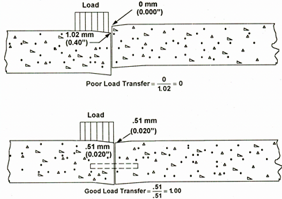
The theoretical LTE ranges from 0 percent (no deflection on the unloaded slab) to 100 percent (equal deflections on the loaded and unloaded slabs). These two conditions are illustrated in figure 63.(14) Generally speaking, the following guidelines can be used to define different levels of LTE:(6)
©National Highway Institute
1 mm = 0.039 inches.
Figure 63. Diagram. Comparison of examples of poor and good load transfer.(14)
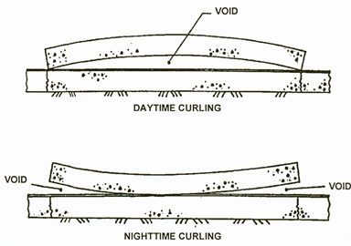
Voids are generally created below slab corners due to pumping and erosion of subbase/subgrade material from repeated loading cycles.(14) Voids represent an area of poor support, which can lead to accelerated cracking and other distresses. Deflection testing can be used to detect the presence of voids by measuring deflections at the slab corner using a series of load levels. However, slab curling (due to temperature differences between the top and bottom of the slab) and warping (due to moisture level differences between the top and bottom of the slab) greatly affect the deflection of the slab during the testing; this concept is illustrated in figure 64 for slab curling.(14) Corner testing should be avoided when the slab is experiencing significant curling or warping because this can lead to misleading indications as to whether a void is actually present.
©National Highway Institute
Figure 64. Diagram. Comparison of slab curling due to temperature differentials in the slab.(14)
There are a number of ways to detect the presence of voids beneath a slab corner. One of the simplest is the comparison of the magnitude of the corner deflection against a project average or pre-established threshold. However, a single maximum value used in the analysis of the corner deflection profile may not be appropriate if load transfer varies significantly from joint to joint. Because of this factor, as well as the influence of test temperature on the results, this method must be viewed as merely a general indicator of potential loss of support.
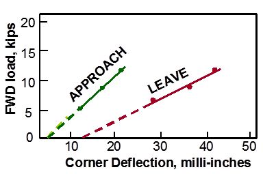
A more robust method of detecting voids is based on the analysis of corner deflections under variable loads.(56) In this method, corner deflections are measured at three load levels (such as 40, 53, and 67 kN (9,000, 12,000, and 15,000 lbf)). The results are plotted to establish a load-deflection relationship at each corner, as shown in figure 65. The figure illustrates that for the approach joint, the load-deflection line crosses the x-axis close to 0 at 0.051 mm (0.002inches). For the leave joint, the load-deflection line crosses the deflection axis at a much greater distance away from the origin, indicating greater deflections under the same load. A line crossing the deflection axis at a point greater than 0.076 mm (3 mils) suggests the potential for a void under the slab.
©National Academy of Sciences. Reproduced with permission of the
TRB.
1 kip = 0.45 metric tons
1 milli-inch = 0.0254 mm
Figure 65. Graph. Example void detection plot using FWD deflection data.(57)
Several mechanistic-based approaches have been developed to determine the presence of voids at slab corners. Shahin developed an approach to detect voids by comparing the measured corner deflections with theoretical corner deflections determined through finite element analysis (FEA), with the difference indicating a potential void.(58) Ullidtz presented a method to detect voids by comparing the modulus of subgrade reaction (k-value) at the corner of the slab to the k-value at the center of the slab, with poor corner support indicated when the k-value at the corner is between 60 and 80 percent of the k-value at the center of the slab.(33)
Nondestructive deflection testing is an integral part of the structural evaluation and development of rehabilitation designs for existing pavement structures. As previously described, deflection testing data can be used to determine the following pavement parameters:
Elastic moduli of the pavement layers.
Subgrade support conditions.
Load transfer across joints and cracks.
Void detection.
These properties can then be used to more accurately model the existing pavement structure and to develop better rehabilitation designs than by assuming typical material properties. In addition, FWD testing can help identify localized areas of weakness or changes in the pavement cross section or material properties, all of which lead to better designs and reduce the risk of premature failure, but without overdesigning the pavement structure.
The material properties obtained from backcalculation can also be used to more accurately model the pavement structure when analyzing its structural capacity or structural remaining life. When layer moduli are backcalculated from deflection data, stresses and strains under traffic can be determined, and the pavement’s fatigue life can be estimated. Once the layer moduli are estimated, the threshold strain value is assigned to control fatigue, and the allowable number of load repetitions is determined from the previous equation.(59)
For inclusion as inputs for the MEPDG, nondestructive testing (NDT) results provide the current in situ layer properties for structural materials.(7) These data can prove to be invaluable in creating a better rehabilitation design rather than estimating material properties and possibly overdesigning the new pavement structure.
Thermal curling and moisture warping can have a tremendous effect on the deflections and stresses in PCC pavements and the designs developed from these inputs. A portion of the slab curvature can be attributed to transient temperature and moisture gradients while the other contributing factors include the built-in temperature gradient and irreversible shrinkage. The latter component is referred to as the effective built-in temperature difference (EBITD). The magnitude of the EBITD is a function of the temperature gradient in the pavement at the time of concrete set, the ultimate drying shrinkage, and the creep characteristics of the concrete. A procedure is available to estimate its magnitude and effect, as described in the following paragraphs.(60,61)
In the procedure, the finite element program ILLI-SLAB is used to analyze the PCC pavement response to the combined effect of loading and temperature differential. The pavement layer and support conditions are first determined through backcalculation of FWD testing data obtained at midslab locations. A range of temperature differentials is then analyzed using ILLI-SLAB. The predicted deflection due to the FWD load is the difference between the loaded slab deflection (load and temperature) and the unloaded slab deflection (temperature only). From this analysis, a plot is developed showing the predicted deflections versus total effective linear temperature difference (TELTD) through the slab depth.
The interpolated deflections as measured in the field, along with the results of the FEA, are then used to estimate the TELTD for each load location. The EBITD is then the difference between the TELTD and the slab’s measured temperature difference at the time of FWD testing.
Materials-related distress or durability problems in PCC pavements are often worse along the joints or at slab corners where moisture can more readily penetrate. Likewise, the deterioration can often be worse near the bottom of the slab compared with the slab surface. The latest FAA advisory circular on NDT includes an approach to assess the severity of materials-related distress below the surface or in a PCC pavement with an HMA overlay.(62) This approach, which is equally applicable to highway pavements, uses the ratio of the impulse stiffness modulus (ISM) at the slab center to the ISM at a joint or corner, where ISM is defined in figure 66.
Where:
ISM = Impulse stiffness modulus, kN/mm (lbf/inch).
P = Applied load, kN (lbf).
d0 = Maximum deflection under the load plate, mm (inches).
The impulse stiffness modulus ratio (ISMratio) is then defined in figure 67:

Figure 67. Equation. ISM ratio.
Where:
ISMratio = Impulse stiffness modulus ratio, kN/mm (lbf/inch).
ISMslab_center= Impulse stiffness modulus at slab center, kN/mm (lbf/inch).
ISMslab_joint = Impulse stiffness modulus at slab joint, kN/mm (lbf/inch).
ISMslab_corner = Impulse stiffness modulus at slab corner, kN/mm (lbf/inch).
An ISMratio less than 1.5 indicates that the pavement is likely in good condition, with little or no materials-related distress at the joint or corner. (Note that the ratio will not be equal to 1 even for a slab in perfect condition because slab deflections are higher at a joint or corner compared with midslab.) An ISMratio between 1.5 and 3.0 signifies a pavement where the durability is questionable. Finally, an ISMratio greater than 3.0 indicates that the durability at the slab joint or corner is poor.
The process to analyze deflection data is commonly referred to as “backcalculation.” In the backcalculation process, pavement layer stiffnesses are determined based on the deflection data and the pavement cross section. Backcalculation derives its name from the fact that it solves for pavement layer properties by knowing the deflection response, which is the reverse of what is commonly done in analyzing a pavement structure using forward calculation. This chapter has presented an overview of backcalculation concepts for flexible, rigid, and composite pavements; a more detailed discussion of the available approaches and their applicability for use with the MEPDG is provided in chapters 4 through 6 for the three pavement types.(7)
This chapter also has discussed other potential uses and benefits of FWD testing and deflection data analysis. For example, FWD data can be used for analyzing the load-carrying capacity and structural remaining life of pavement structures, for determining LTEs, for evaluating the extent of materials-related distress, and for determining the presence of built-in curling.