FHWA Tunnel Leak Assessment
|
|
Download the report in PDF format: tlabcainterim.pdf (1963 KB) To view PDF files, you can use the Adobe® Reader®. |
FHWA Tunnel Leak Assessment Team
Peter W. Osborn
Gary Jakovich
Roland Nimis
Matt Greer
The Federal Highway Administration (FHWA) Tunnel Leak Assessment Team (A-Team) for the Boston Central Artery Tunnel (CA/T) Project was formed and activated in response to Administrator Mary Peters' request for an independent FHWA engineering assessment. Immediate action was taken by King Gee, Associate Administrator for Infrastructure, and Myint Lwin, Director, Office of Bridge Technology, who selected and contacted the team members. The team members are:
The Team Mission was as follows:
The Team arrived in Boston on December 19, 2004 and conducted the assessment from December 20-22, 2004. Background and technical materials were sent to the team for review prior to the Team's arrival. The assessment consisted of an opening meeting with Division Administrator Stan Gee and his staff who briefed the Team on the background and the current tunnel leak situation. This was followed by additional review of project documentation and a nighttime field tunnel inspection (to observe tunnel sealing operations and the inspection of wall panels). Interviews were conducted with 16 individuals from Bechtel/Parsons-Brinkerhoff (B/PB), Massachusetts Turnpike Authority (MTA), and the Federal Highway Administration Massachusetts Division (FHWA) (collectively referred to as The Project) who are currently or have been involved with the Project. A list of individuals interviewed and documentation reviewed by the Team is provided in the Appendix to this report. A closeout meeting was held with the Division Office on December 22, 2004.
Following field review, the Team prepared the draft the report and continued to monitor the progress of the leak sealing efforts, while the report underwent internal review. This interim report contains data that was available as of March 23, 2005.
For the purpose of the A-Team's assessment and this report, the Project leaks are classified into two types: Slurry Wall Panel Leaks and Roof/Wall Interface Leaks.
These are leaks with high flow rates, such as the one that occurred on September 15, 2004 when Panel EO-45 was breached, resulting in water flow into the tunnel. The initial flow rate was estimated to be as high as 300 gallons per minute (gpm). Field reports indicate that Panel EO-45 contained defects and inclusions that were caused by poor quality control and quality assurance during slurry wall construction.
As a result of the EO-45 panel breach, the project is reviewing construction records to determine if similar construction problems occurred in other panels and inspecting those panels for defects. In addition, the project is inspecting all slurry wall panels project wide. To date, approximately 63% of all slurry wall panels have been inspected and thus far one additional panel has been identified as in need of major repair similar to panel EO-45.
Repair Options reviewed by the A-Team: Two basic repair schemes that have been proposed, one from the consultant retained by the project (MRCE) and one, with two variations, from the contractor, are being evaluated for EO-45. The repair scheme adopted for EO-45 will likely serve as the model for repair of the other panel identified with major deficiencies. 56 other locations have been identified as minor defects and are actively being repaired.
MRCE Repair Proposal - Reconstruct the entire concrete panel to provide a repair that most closely resembles what would have been in place had the original work not been faulty.
Contractor Repair Proposals - Repair incorporates a combination of injecting concrete grout behind the panel to fill the inclusion and then attaching a steel plate over the interior wall face to seal the opening. The second variation of the contractor's proposal would secure a 10-inch structural concrete slab over the steel plate for added strength to support any forces that might be imposed upon the wall.
While the A-Team does not have a preferred proposal it is confident that any of the proposals would provide an adequate repair conditioned upon clear demonstration that the repair will be structurally sound, provide a durable and effective barrier against moisture from entering the tunnel, be relatively maintenance free, and neither interfere with other tunnel systems nor detract from the tunnel's finished appearance. Other, but not exclusive, key factors during construction that must be considered and adequately addressed are safety impacts, the potential for adverse impacts upon abutting property, traffic disruption, adverse impacts and duration of inconvenience to the public and the total time to complete the repair.
The fact that the Team has reviewed the two proposals should not be misconstrued that there are no other proposals that could satisfy the repair requirements. The FHWA Massachusetts Division will review and provide concurrence for any proposed repair only after being convinced that the repair is adequate and does not pose unacceptable consequences during construction.
These leaks are of lesser magnitude ranging from dampness to dripping type leaks, but are occurring at a greater number of locations. They are referred to as "chronic low level leaks" and can be expected to occur to some degree because the tunnel is constructed significantly below the water table. The design of the tunnel incorporates a waterproofing membrane applied to the top slab (roof) of the tunnel to prevent the intrusion of water. The membrane is placed on the roof and 12 inches up the slurry wall. However, water is still finding its way to/through the roof/slurry wall connections at numerous locations. The project specifications require that the system be "watertight". The only allowance in the specifications is for dampness; seepage or dripping leaks through the slurry wall are prohibited.
In an effort to address problems that arose in the application of waterproofing during Contract C11A1 and subsequent Contract C17A2, a Waterproofing Task Team (WT-Team) comprised of the Massachusetts Highway Department (MHD), the FHWA and B/PB personnel was formed in March 1997 to provide recommendations for selection and installation of waterproofing systems for the Project.
To address the chronic low level leaks, a Leak Task Force (Task Force), comprised of FHWA, MTA, B/PB personnel, was appointed in mid-2000 to define the extent of the problem and to provide repair guidance to the field. An inventory maintained by the Project originally identified approximately 724 leak locations (based on Summer 2004 Inspection) for the entire Central Artery Tunnel. The inventory is being used as a base to monitor the progress of sealing of the leaks. The number of leaks changes on a daily basis as leak sealing efforts progress; the inventory is updated accordingly. The Team is comfortable with the project's methodical approach to sealing all leaks and their effort to seal all leaks by the end of September 2005, and will continue to monitor the work.
Finding: Chronic low level leaks and seeps were noted and are to be expected to some degree due to the tunnel depth below the water table. The project has developed a systematic approach to sealing the leaks and is currently in the process of this work. Sealing of all leaks is expected to be complete in the summer of 2005.
Recommendation: The project should continue with the sealing procedure as currently underway and ensure that qualified personnel complete the repairs. It is recommended that the project maintain consistency with regard to the field engineer in charge and the leak sealing crews as this type of work is specialized in nature and requires intimate knowledge of the tunnel conditions.
Finding: The project has completed a temporary repair of the September 15, 2004 Slurry Wall Breach. Permanent repair alternatives are under review and consist of two general approaches: (a) remove and replace; (b) welded steel plates (with or without encapsulation of the plate by reinforced concrete) and grouting.
Recommendation: The team recommends that the project carefully consider options requiring minimal disruption and low overall risk with respect to the tunnel and adjacent structures, but assuring durability and watertightness. The removal and replacement option should be considered with the understanding that it requires dewatering and will require a longer duration to complete the repair. If this option is necessary to assure durability and watertightness, the construction procedures should be tested for structural integrity and watertightness before use. Whichever option is selected must be implemented quickly to ensure the safe and uninterrupted passage of the traveling public.
Finding: Detailed inspections of the slurry wall panels for the C17A1 construction contract have resulted in the discovery of additional defects, which will need some form of remediation. In addition, the project is in the process of inspecting all slurry wall panels project wide.
Recommendation: The Project is encouraged to quickly complete the inspection of all panels and develop a standardized inspection process and related documentation. Additionally, the Project should develop an in-service inspection program for periodic inspection for leaks.
The A-Team believes that the Project is appropriately addressing the tunnel leaks. The September 15, 2004 Slurry Wall Breach appears to be isolated to a discrete section of the tunnel and primarily the result of poor quality control during construction. The project has successfully installed an interim repair and is actively designing the permanent fix while completing an investigation of all suspect slurry wall panels. The A-Team found that the Project is continuing repair of the chronic low level leaks and is committed to completing all repairs before the project completion date to meet specifications for the tunnel. The Team will continue to monitor that work.
The Federal Highway Administration (FHWA) Tunnel Leak Assessment Team (A-Team) for the Boston Central Artery Tunnel (CA/T) Project was formed and activated in response to Administrator Mary Peters' request for an independent FHWA engineering assessment. Immediate action was taken by King Gee, Associate Administrator for Infrastructure, and Myint Lwin, Director, Office of Bridge Technology, who selected and contacted the team members. The team members are:
The Team Mission was as follows:
The Team arrived in Boston on December 19, 2004 and conducted the assessment from December 20-22, 2004. Background and technical materials were sent to the team for review prior to the Team's arrival. The assessment consisted of an opening meeting with Division Administrator Stan Gee and his staff who briefed the Team on the background and the current tunnel leak situation. This was followed by additional review of project documentation and a nighttime field tunnel inspection (to observe tunnel sealing operations and the inspection of wall panels). Interviews were conducted with 16 individuals from Bechtel/Parsons-Brinkerhoff (B/PB), Massachusetts Turnpike Authority (MPA), and the Federal Highway Administration Massachusetts Division (FHWA) (collectively referred to as The Project) who are currently or have been involved with the Project. A list of individuals interviewed and documentation reviewed by the Team is provided in the Appendix to this report. A closeout meeting was held with the Division Office on December 22, 2004.
For the purpose of the A-Team's assessment and this report, the Project leaks are classified into two types: Slurry Wall Panel Leaks and Roof/Wall Interface Leaks.
These are leaks with high flow rates, such as the one that occurred on September 15, 2004 when Panel E045 was breached, resulting in water flow into the tunnel. The initial flow rate
was estimated to be as high as 300 gallons per minute (gpm). Field reports indicate that Panel E045 contained defects and inclusions that were caused by poor quality control and quality assurance during slurry wall construction.
As a result of the EO-45 panel breach, the project is reviewing construction records to determine if similar construction problems occurred in other panels and inspecting those panels for defects. In addition, the project is inspecting all slurry wall panels project wide. To date, approximately 63% of all slurry wall panels have been inspected, and only one additional panel has been identified as in need of major repair similar to panel EO-45. Two basic repair schemes that have been proposed, one from the consultant retained by the project (MRCE) and one from the contractor, are being evaluated for EO-45. The repair scheme adopted for EO-45 will likely serve as the model for repair of the other panel identified with major deficiencies. 56 other locations have been identified as having minor defects and are being repaired.
These leaks are of lesser magnitude ranging from dampness to dripping type leaks, but are occurring at a greater number of locations. They are referred to as "chronic low level leaks" and can be expected to occur to some degree because the tunnel is constructed significantly below the water table. The design of the tunnel incorporates a waterproofing membrane applied to the top slab (roof) of the tunnel to prevent the intrusion of water. The membrane is placed on the roof and 12 inches up the slurry wall. However, water is still finding its way to/through the roof/slurry wall connections at numerous locations. The project specifications require that the system be "watertight". The only allowance in the specifications is for dampness; seepage or dripping leaks through the slurry wall are prohibited.
In an effort to address problems that arose in the application of waterproofing during Contract C11A1 and subsequent Contract C17A2, a Waterproofing Task Team (WT-Team) comprised of the Massachusetts Highway Department (MHD), the FHWA and B/PB personnel was formed in March 1997 to provide recommendations for selection and installation of waterproofing systems for the Project.
To address the chronic low level leaks, a Leak Task Force (Task Force), comprised of FHWA, MTA, B/PB personnel, was appointed in mid-2000 to define the extent of the problem and to provide repair guidance to the field. An inventory maintained by the Project originally identified approximately 724 leak locations (based on Summer 2004 Inspection) for the entire Central Artery Tunnel. The inventory is being used as a base to monitor the progress of sealing of the leaks. The number of leaks changes on a daily basis as leak sealing efforts progress; the inventory is updated accordingly. The Team is comfortable with the project's methodical approach to sealing all leaks and their effort to seal all leaks by the end of September 2005, and will continue to monitor that work.
2.1 General Tunnel Construction
The portion of the Central Artery system that is the subject of this report is a cut-and-cover tunnel structure that employs SPTC (Soldier Pile Tremie Concrete) walls as the vertical sidewalls of the tunnel. These walls have been commonly referred to as "slurry walls" because their construction utilizes placement of a viscous material known as "slurry", that has a specific gravity greater than water, into the excavated space to prevent the intrusion of water and soil prior to the introduction of concrete. The height of the slurry walls extends from street level in Boston down as much as 120' where they are embedded into rock. The strength of the walls derives from heavy, 36" deep, steel I-beams that are employed as soldier piles. These piles, which are embedded in rock at their base and serve as the support point for the tunnel's floor and roof framing, are the vertical members that carry the weight of the tunnel components down to the foundation. They also are the members that give the slurry wall its strength and stiffness to withstand lateral earth and hydrostatic loads. The piles are spaced between four and six feet apart depending on the location. The space between the piles is filled with concrete. The slurry wall thickness is nominally 42" and is intended to provide 3" of concrete cover over the surface of the pile flanges.
Construction of the walls begins with general dewatering of the area followed by excavation of the wall trench for a short length of wall. Slurry is introduced into the trench to prevent caving. The piles are then lowered into place. Where called for on the plans, reinforcing cages are lowered into position between the piles to provide what is essentially reinforcement to control temperature induced cracking of the slurry wall concrete. Concrete is then placed by tremie pipe between the piles to construct the slurry wall panel (a "panel" is the concrete section between adjacent soldier piles). Finally, after about 40' of slurry wall has been constructed on each face of the tunnel, the soil between the walls is excavated down to the bottom of the tunnel invert to expose the interior face of the walls down to that level. The profile grade of the tunnel takes the roadway elevation from ground level down to as much as 100' beneath the surface and back up again. Therefore, the depth of slurry wall that is exposed by the excavation varies accordingly.
The top and bottom surfaces of the tunnel consist of concrete slabs that are constructed to butt up against the slurry walls at the appropriate elevation (vertical position) on the slurry wall. The tunnel floor is essentially a thick concrete slab that is cast between the slurry walls and is connected to them with mechanical connectors. The depth of the slab accommodates the placement of the supply air ducts. The roof of the tunnel is a concrete slab that is placed between the slurry walls and is supported by the roof girders.
This general construction is shown in Figure 1. It should be noted that, although the detail shown indicates the top of the slurry walls located a short distance above the tunnel roof, this is not normally the case. The distance from the top of the slurry wall to the top of the roof slab can be as much as 70' at the tunnel's deepest point.
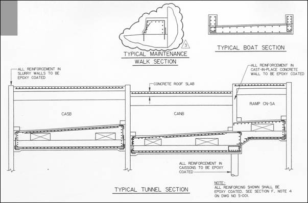
Figure 1: Typical Tunnel Section
The floor slab is cast on top of a concrete leveling slab (mud slab) that is cast against undisturbed ground. However, in reality the support for the floor is not the underlying soil but rather is designed to come from the soldier piles. In effect, the floor slab hangs from the soldier piles, see Figure 2. This allows for the introduction of facilities to be placed underneath the tunnel in the future.
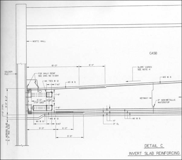
Figure 2: Detail of Floor Slab to Soldier Pile Connection
Similarly, the roof of the tunnel hangs from the soldier piles. At every soldier pile a steel I-section roof girder is connected to the pile with bolted connections. The girder spans transversely across the width of the tunnel to attach to the soldier piles on the other side of the tunnel as shown in Figure 3.
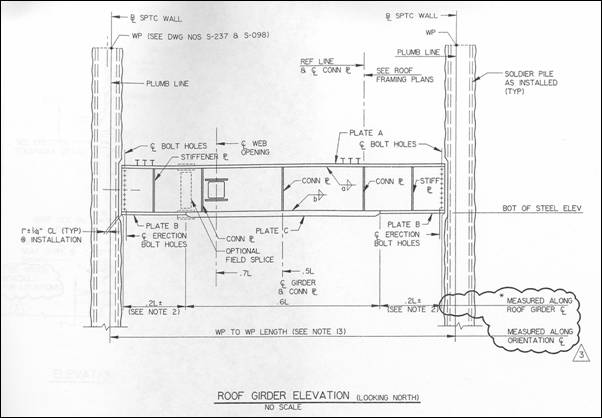
Figure 3: Roof Girder Placement
The roof structure is constructed as a composite beam/slab section and is designed to support the depth of backfill that is placed from the top of the tunnel to the ground surface (Boston street level). The depth of backfill varies from several feet to over 80 feet in the deepest section. A detail of this construction is shown in Figure 4.
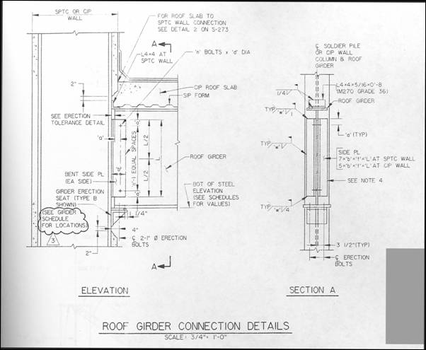
Figure 4: Roof Girder Connection to Soldier Pile Details
Because of Boston's seashore location and the fact that, in some parts of the city, street level is only a few feet above sea level, the CA/T is below the water table for most of its length. Therefore, water infiltration was a major concern for the designers. The Project issued a concept report in 1990 that discussed a variety of waterproofing options for the various components of the tunnel and made recommendations as to which would offer the best solution. The recommendations were as follows:
Slurry walls: No waterproofing to be used on the walls. The exterior face of the slurry wall is inaccessible for waterproofing by nature of its construction. In the report the statement was made that "Slurry walls are usually fairly free of leaks." Given the 42" thickness of the walls and the intent to provide in the specifications that all running leaks would be grouted, the decision was taken not to require the application of waterproofing on the interior surface of these walls.
Bottom slab: High-density polyethelene (HDPE) bentonite sheet was recommended. This sheet is a laminate of three materials: high-density polyethelene sheeting, chemically modified bentonite, and a spun polypropylene overlay.
Top slab: Liquid-applied rubberized asphalt was recommended. HDPE bentonite sheet was also recommended.
The project specifications required that the waterproofing system provide a "watertight" system. If leaks or dampness occurred they were to be sealed, either by repairing the membrane if still accessible, or if not accessible, by sealing with injected grout. It should be noted that, for the slurry wall, dampness of the wall surface was acceptable as long as the wall surface did not exhibit any running water.
Key waterproofing system requirements were:
Waterproofing must adhere permanently and continuously to the roof slab or, in the case of the floor slab, be permanently and tightly confined against the bottom.
The system must be capable of watertight terminations and transitions to adjoining construction.
To obtain a high quality installation the project specifications required that the contractor submit the following information for review and approval before commencing the work.
Materials data, including technical literature, standard details, product specifications, installation instructions, and any supplementary details or instructions unique to the project;
Material samples if required by the Engineer;
Material certifications;
Installation drawings;
Detailed field quality control procedure describing inspection and test procedures and frequencies, documentation methods, and resumes' of testing personnel;
Resume and credentials of manufacturer's technical representative and the waterproofing installer;
Materials safety data.
A further requirement of the specifications was that the contractor furnish documentation of the manufacturer's representative's inspections with appropriate data included following the installation of waterproofing material.
During the preliminary design process The Project established standard details and supplemental specifications for the waterproofing to be used on the CA/T contracts. Permissible systems for the slabs included those mentioned above and additionally, pre-formed self-adhering sheet membranes and the PVC system, a new engineered system employing waterstops and requiring greater specialized training in its application.
The slurry walls generally are not waterproofed as they are considered to be sufficiently impermeable by design. Intrusion of water at the bottom of the tunnel is prevented through the use of a waterproofing layer applied beneath the bottom slab and carried up the face of the slurry wall approximately one foot (see Figure 5).
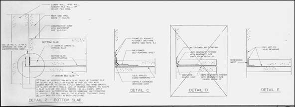
Figure 5: Bottom Slab Waterproofing Details
Similarly, intrusion of water at the top of the tunnel is managed by the application of a waterproofing layer applied to the top of the tunnel roof and carried up the face of the slurry wall approximately one foot as shown in Figure 6.
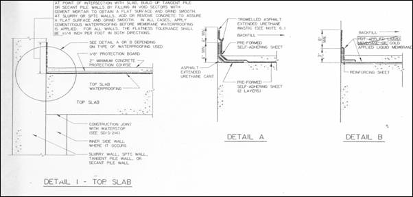
Figure 6: Top Slab Waterproofing Details
Construction of the sections of the Central Artery that utilized slurry walls began in 1995 with contract C11A1. In an effort to address problems that arose in the application of waterproofing during this contract and subsequent contract C17A2, a Waterproofing Task Team (WT-Team) comprised of MHD, FHWA, and B/PB personnel was formed in March 1997 to study the systems permitted by the specifications with respect to their materials, their installation, training of the applicators, and quality assurance/quality control (QA/QC) procedures. The WT-Team investigated the various waterproofing systems and conducted field observations of their installation. The general conclusion of the team was that the waterproofing systems permitted for the CA/T were proven products that work when the installation is done correctly.
The WT-Team felt that almost all problems (95%) were the result of unsatisfactory quality control. Several important areas of concern cited were surface preparation, protection of installed waterproofing, and training of applicators. The WT-Team issued a report dated July 31, 1997 that contained the following findings and recommendations:
Importance of Waterproofing System: Waterproofing is the single most important construction activity in providing a watertight structure. Construction field personnel must be able to devote sufficient time to overseeing this work.
Recommendation: Provide additional B/PB personnel dedicated to waterproofing oversight.
Surface Preparation: This was the foremost deficiency identified by the Task Team in the field.
Recommendation: Stricter enforcement of specification and manufacturer requirements for surface preparation before starting the waterproofing installation.
Quality Control: The contractor's performance of Quality Control (QC) of the waterproofing work was inadequate. There was no QC plan.
Recommendation: The contractor must accept responsibility for quality control by developing and implementing a QC plan.
Material Application: Problems such as damage to materials, premature hydration, application over "green" concrete were identified. Often these problems were due to the aggressive construction schedule.
Recommendation: Eliminate the use of bentonite systems (premature hydration) and polyurethane (gassing - forming bubbles in the membrane because of reaction with "green" concrete; and low adhesion strength). Require testing of all materials to insure compatibility with the project construction environment and schedule.
Training: The construction oversight field personnel of B/PB and contractor's personnel needed training on waterproofing application requirements.
Recommendation: Provide detailed training for B/PB's field and QA personnel, and the contractor's QC and application personnel on the proper surface preparation and application procedures with emphasis on the CA/T specifications and the project environment.
Waterproofing Requirements: Inconsistencies between manufacturer's literature or recommendations, contractor's submittals, and project specifications were identified.
Recommendation: Add a requirement to the contract specifications that says if a conflict exists within the above-mentioned documents, the most stringent requirements shall apply.
Manufacturer's Recommendations: It was noted that local sales representatives had been making recommendations that dismissed or conflicted with the manufacturer's documentation and had essentially been acting as the manufacturer's technical representative. This was not acceptable since the contract does not regard sales representatives as having the authority to make technical decisions or perform inspections.
Recommendation: Enforce strict adherence to all manufacturer's written requirements contained in the approved submittal(s), and require the contractor to identify in writing the manufacturer's qualified technical representative.
CA/T specifications require the contractor to take full responsibility for quality control of project activities. As such, the contractor must provide personnel to conduct material sampling and testing in accordance with project specifications and also perform field inspection of construction activities. Quality control personnel are required to perform their function independent of the contractor's production constraints.
Quality assurance, on the other hand, is normally the responsibility of the owner (MHD). In the case of the CA/T project, B/PB was contracted to function as the owner's representative for oversight of design and construction. Therefore, B/PB was charged with the responsibility to perform QA checks of the contractor's work. To carry out their function B/PB had QA personnel such as their materials staff. Also, for each contract of the CA/T project, B/PB provided a resident engineer (RE) and a number of field engineers (FE).
Quality control of waterproofing was documented through the use of a form that was developed in February 1997. The form identified the various required submissions so that it would be clear if an item had not been completed. It also identified the various preparation steps for the various permitted systems to insure that all were completed. Lastly, the form required the installation test results (typically membrane thickness) to be written down to insure that these were performed. All information was to be provided on the form by the installer, the technical representative, and the contractor QC personnel. Quality assurance by B/PB field personnel consisted of reviewing the QC form to insure that all appropriate information and activities had been checked off and spot checking the contractor's installation activities. For example, B/PB personnel were on site when the initial application of a system was being performed.
As mentioned in the preceding section, the WT-Team identified inadequate quality control of the waterproofing application as a critical issue. The result was that improved quality control procedures were instituted. Training was developed for CA/T project FE and QA personnel along with the contractor's QC personnel and waterproofing applicators. The training course focused on engineering, material, application, and quality control requirements for each system that was permitted for use on the CA/T project. Presentations were made by the manufacturer's qualified technical representatives to explain material characteristics and application requirements, such as surface preparation, within the project specifications.
The Waterproofing Task Team's recommendations led to improved waterproofing system installations. However, water is still finding its way to the roof/wall interface connections at numerous locations. Project specifications state that dampness on the wall is acceptable but seepage or dripping leaks are not. A primary concern with these leaks is the corrosion of the roof steel I-beams particularly at the soldier pile connections.
On Wednesday, September 15, 2004, at about 11:45 a.m., a leak opened up in the tunnel slurry wall behind the architectural precast concrete wall panels on the east side of the I-93 Northbound tunnel at Station 104 + 53. This location is within the C17A1 contract limits. Groundwater and saturated sand entered a through-wall void and caused flooding on the right two lanes of the roadway, requiring the lanes to be closed to traffic. The CA/T Project was notified by the operator of the tunnel, the Massachusetts Turnpike Authority (MTA) Operations, at approximately 1:30 p.m. The MTA and contractor crews were mobilized to remove sand, clear drains, and evaluate the leak. A chronology of events as provided by the project staff (Stavola, 2004) is summarized in this section.
When the leak was discovered on September 15, 2004, a water flow rate equated to the volume of an 8-inch pipe, streamed out of the slurry wall into the back of the architectural wall panel, releasing water underneath and onto the roadway (see Photos 1 and 2). Significant amounts of sand washed in with the water and pooled across two lanes of traffic before flowing to the drains.
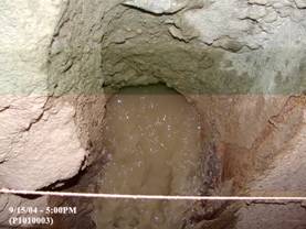 Photo 1: Slurry Wall breach |
 Photo 2: Sand in roadway |
MTA Operations mobilized to the area and restricted traffic to the remaining two lanes. The crews removed accumulated sand from the walkway, roadway, roadway drain lines, and low point pump station wet well. The deposited soil was described as a uniform clean, fine sand. A layer of sand approximately 18 inches deep was reported in the void space between the architectural panels and the slurry wall for a distance of 20 feet on either side of the leak. Traffic in the tunnel continued to be restricted to three lanes during the evening peak rush hour, which caused significant delays to I-93 northbound motorists.
By 9:00 p.m. on September 15, 2004, the 10-feet high architectural wall panel was removed at the leak location to allow for a more complete inspection. The flow rate at this time had reduced from initial estimates of 300 gpm to approximately 150 gpm; the flow was also less turbid. The wall breach was described as an estimated 12-inch by 12-inch square hole at the slurry wall face (see Photo 3). By 11:00 p.m., the flow had further reduced to about 75 gpm.
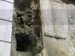
Photo 3: Breach in Slurry Wall Panel
The hole was probed with a rod and was found to extend horizontally three feet back into the wall and vertically down to a depth of 4 feet on about a 60-degree angle away from the front face of the wall. Soft loose material was encountered at the bottom of the void and a soft bentonite paste was observed on each side of the hole; this material was easily removed by hand. A vein of similar material composed of sand, stone and cement/bentonite paste was observed above the hole. An estimated ½ inch thick shotcrete layer was observed both over this vein of soft material to the south of where it was exposed, and on the adjacent concrete surface of the wall.
Located just above the hole on the adjacent soldier pile, the soldier pile endstop treatment installed under contract C11A1 was visible to a width of 6 to 8 inches and a height of 1 foot. The endstop treatment consists of a 1/8 inch thick steel plate, tack welded to the pile flanges to facilitate cleaning the end piles of the primary panel during excavation of the secondary panels. The soldier pile acts as the panel end stop while the plate, normally removed during excavation of the adjacent panel, facilitates cleaning of the interior of the pile flanges. Three inches of sound concrete covered with bentonite paste was bonded to the endstop plate adjacent to the exposed portion. A 1/2 inch thick layer of shotcrete covered the wall up to the end pile, and some was also observed on the surface of the endstop plate.
Drilling attempted during leak sealing efforts indicated the concrete 1 foot directly beneath the hole was less than 1 foot thick. Drilling attempts 2 feet directly below the hole indicated there was sound concrete to some depth. Additional drilling to the north and in the adjacent C11A1 panel to the south revealed sound concrete to depths of up to 3 feet. No evidence of a reinforcing cage was apparent in the void or encountered in any drill holes beneath the void.
Upon removal of the architectural panel on Wednesday evening, September 15, 2004, (after traffic had lessened), a temporary wood plug was installed to decrease the flow to a trickle (see Photos 4 and 5). The installation of the plug allowed the MTA to restore the tunnel to full operating conditions by 5 a.m. the following day.
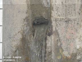 Photo 4: Flow Rate Dissipating |
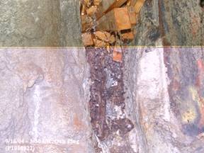 Photo 5: Breach plugged and grouted |
At approximately 8 p.m. on Thursday evening, September 16, 2004, crews reopened the wall area and completed an interim leak repair utilizing chemical grout and the installation of face support. Face support was provided through the installation of a steel plate that was grouted solid with rapid setting mortar between the repair plug and the plate. No flow was evident at the completion of the work (see Photos 6 and 7). Finally, to address the issue of any potential voids that may have formed behind the wall, limited drilling and grouting was conducted from the surface.
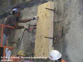 Photo 6: Plywood Form
 |
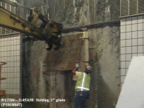 Photo 7: Steel Plate
 |
The team reviewed available construction records for the breached panel. Below is a discussion of the key construction issues identified from the review of the inspection records and interviews with the project personnel.
Based upon our review of the project documentation and interviews with project personnel it is evident that the slurry wall breach can be attributed to inadequate and incomplete cleaning of the slurry trench prior to concreting and the failure to remove the endstop treatment (as required). This installation deficiency appears to have resulted in a soft material inclusion that was subject to erosion from groundwater pressure, ultimately creating a breach in the wall to relieve the high hydrostatic pressure behind the wall.
Due to the improper cleaning of the trench and failure to remove the endstop, the contractor was unable to install the full reinforcing cage. The contractor elected to modify the steel cage to allow installation, contrary to plan details and without the written permission of the Engineer. The concrete lagging between soldier piles has a resultant vertical cold joint, is not monolithic, and is not fully reinforced to the web of the interface pile.
Records further indicate that the tremie placement was made with one tremie pipe, which is also a contract deviation and an unacceptable practice. This method can result in unacceptable unbalanced loads on the center pile, causing the potential for slurry inclusions and/or can result in an inclusion of contaminants that typically are pushed out of the excavation by the concrete when properly tremied. The vertical seam of loose soil adjacent to the pile may be attributable to this deficient placement method.
After the September 15, 2004 slurry wall panel breach, the Project started an investigation to identify other panels with the potential for a slurry wall breach. This staged investigation started with the panels most similar to the breach panel and extended out to a larger population to consider the panels installed by all 13 slurry wall contracts.
This first phase of the inspection program identified 10 panels that met the initial screening requirement of similar wall construction at the interface with a primary panel installed under other contracts. Table 1 is a summary of the inspections completed.
| Panel No. | Pile no's - Contractor | Description - Selection criteria | Current Condition | Inspection Result |
|---|---|---|---|---|
| W-1 | G18W - PKC H1W - MCC |
secondary panel at contractor interface | wet at roof - no sealing yet | Concrete sound - no inclusions or defects evident |
| MW-82 | MP-10 PKC MP11 - MCC |
secondary panel at contractor interface | Dry | Dry soil inclusion against end pile MP10 from 12'-4" to 21' high |
| M-36 | F22M - MCC G0M - PKC |
secondary panel at contractor interface | dry - prior roof sealing | Concrete sound - no inclusions or defects evident |
| M-37 | G18M - PKC H1M - MCC |
secondary panel at contractor interface | dry - prior roof sealing | Concrete sound - no inclusions or defects evident |
| E-25 | G0E - MCC G1E - PKC |
secondary panel at contractor interface | dry - prior roof sealing | Concrete sound - no inclusions or defects evident |
| E-26 | G18E - PKC H1E - MCC |
secondary panel at contractor interface | dry - prior roof sealing | Concrete sound - no inclusions or defects evident |
| E-17A | B15E - MCC B16E - Walsh |
secondary panel at contractor interface | dry at roof, wall moisture | Moist bentonite inclusion against end pile B16E from 4' to 14' high |
| E-18 | F2E - Walsh F3E - MCC |
secondary panel at contractor interface | dry - prior roof sealing | Concrete sound - no inclusions or defects evident |
| M-69B | N12M - MCC N13M - MCC |
secondary panel visible water flow | 1 gpm flow at floor (approx) | Foreign material inclusion at walkway & end pile N12 to 8' high, end stop ir-regularity, panel orig cast in place, CIP |
| M-69B* | MP25 - MCC MP26 - MCC |
secondary panel originally CIP | dry - needs added inspect | Should be monitored periodically in lieu of M-69B finding - currently dry |
Of the 10 additional panels inspected, 3 contained inclusions as detailed in the bolded text above. As a result of the higher than expected 30% incidence rate, the Project determined they would inspect all of the interface piles along the C17A1 alignment, a total of 237 joint locations. The inspections were performed by removing the stainless steel panels above the precast architectural panels to expose the top half of the slurry wall surface. If conditions encountered were determined to contain defects, the entire architectural panel was removed for a detailed examination. All 237 joint locations have been inspected. A total of 25 defects were identified, two of which (including panel EO-45) will require major repair. The remaining 23 will require minor repair (patching).
A detailed record search has been completed by the project. All documentation maintained electronically has been identified for the thirteen contracts that include slurry wall construction in the contract scope. Contractor Non Conformance Reports (NCR's), Requests for Information (RFI's), Field Engineer Daily Reports (FEDRs) and Project Deficiency Reports (DR's) have been examined to screen out walls that may require additional detailed inspection.
In addition, the project is in the process of inspecting all slurry wall panels throughout the project. As of March 23, 2005, 63% of all slurry wall panels had been inspected. 33 additional minor defects have been identified.
The roof/wall interface leaks are chronic low-level leaks ranging from dampness to dripping that are occurring at a large number of locations. The Leak Task Force developed an inventory of these leaks throughout the project in an effort to take control of the problem and develop a solution. The project personnel have suggested several avenues by which water is finding a way into the tunnel. These are:
Through the interface between the Slurry wall concrete and flange and web of the pile. Shrinkage of the concrete causing it to lose its bond with the pile is a possible pathway for water. Another possibility is inadequate cleaning of the trench prior to placement of concrete, leaving deleterious material on the steel that prevented good bonding of the concrete. A third source of bond loss that was mentioned as a possibility for some contracts is the result of using a hoe-ram to remove concrete from the piles to expose the interior flange for attachment of the girders. The impact of the hoe-ram may have produced enough vibration to break the concrete/steel bond.
The interface of the roof membrane with the slurry wall. This area is problematic in that the success of the membrane at this interface is dependent on a good bond between the membrane and the wall face. Because the slurry wall surface is by nature uneven and rough in texture, the specifications require that the contractor smooth this surface to make it acceptable for membrane to properly conform and adhere to it. Doing this work is a very laborious effort and one where quality control could possibly be compromised.
Interfaces between different types of membrane. Since several types of waterproofing systems were permitted in the specifications, the contractors were able to select their preferred system as long as they provided information and details to demonstrate it to be compatible with a previously installed system where it was necessary to interface. The result is that, even though details are developed to mitigate the situation, interfacing two systems is a natural weak link and thus subject to suspicion.
Through the upper portion of the slurry wall, above the termination point of the turned-up membrane. The concern here is that the water migrates through the interior face of the wall where excavation once left the wall face exposed prior to placement of the backfill, finds a way to the concrete/pile interface, and trickles down the web of the pile where it emerges at the top of the tunnel.
As stated earlier in this report, leaking in the Central Artery tunnel sections constructed with slurry walls falls into two distinct categories.
The first, illustrated by the September 15, 2004 breach, is indicative of a defect in the construction of a slurry wall panel. Project personnel have completed the inspection of all panels on the contract where the September 15, 2004 breach occurred (C17A1). In addition, the project is currently inspecting all slurry wall panels project wide. The second category of leak is the chronic low-level infiltration of water through the tunnel roof/slurry wall interface or through the slurry walls themselves.
Remediation efforts for these two types of leaks are described in the following sections.
Defective panels, as exemplified by the September 15, 2004 breach, are serious and must be repaired as soon as possible. The Massachusetts Transportation Authority (MTA), which assumed authority over the project from the Massachusetts Department of Highways (MHD) in 1997, retained a consultant, Mueser Rutledge Consulting Engineers (MRCE), to investigate the problem and develop a recommendation for repair of the defective panel.
Repair Options reviewed by the A-Team: Two basic repair schemes that have been proposed, one from the consultant retained by the project (MRCE) and one, with two variations, from the contractor, are being evaluated for EO-45. The repair scheme adopted for EO-45 will likely serve as the model for repair of the other panel identified with major deficiencies. 56 other locations have been identified as minor defects and are actively being repaired.
MRCE Repair Recommendation
MRCE's recommendation is to remove and reconstruct, in horizontal lifts limited to 2' or 3' in height, the defective portions of panel EO-45. The repair would be done to the portion of the wall height that is exposed within the tunnel, i.e. from just below the top of the tunnel maintenance walk to the bottom of the tunnel roof slab (approx. 27'). This work involves the following steps:
Installation of devices to monitor the effect of the dewatering operation. It is recommended that deformation monitoring points (DMP's) be installed on columns in the parking garage of the Federal Reserve Bank (FRB). It is also recommended that piezometers be installed adjacent to the slurry wall and on the east side of the FRB to measure the groundwater levels.
Install a dewatering system outside of the wall to remove the water pressure on the wall and thereby prevent the flow of water into the tunnel during the repair operations. The groundwater level would be lowered on the outside of the wall to about the level of the tunnel roadway (approximately Elev. +30') before beginning the actual panel repair.
Perform the removal and replacement of the defective portion of the panel in horizontal stages 2 to 3 feet in height working up from the maintenance walk to the roof level.
Strengthen the soil on the outside face of the wall panel by compaction grouting through the use of high pressure injection of grout into the soil.
Contractor's Repair Recommendations
The contractor has proposed two repair methods.
Repair No.1 consists of injecting grout behind the panel and installing steel plating over the interior face of the panel. The plating would be installed in horizontal sections starting at the level of the maintenance walk and proceeding up to the tunnel roof. The plating would be designed to be equal in strength to the existing concrete section. The plating would be secured by welding it to the exposed flange of the adjacent soldier piles. The horizontal joint between individual plate sections would be welded to prevent leakage of water between them. Also, grout would be injected behind the plating in each stage to fill any gap between the existing concrete panel and the steel plating.
Repair No. 2 incorporates the elements of Repair No. 1 and supplements them with the construction of a structural slab (approximately 10" thick) of reinforced concrete cast over the steel plate. The concrete slab would be secured to the interior face of the slurry wall by dowels anchored into the concrete of the panels on either side of Panel EO-45. Essentially it is a belt and suspenders approach in that it employs two structural elements (a steel plate and a concrete slab) each designed to resist the pressure on the slurry wall panel.
A-Team Repair Proposal Observations: While the A-Team does not have a preferred proposal it is confident that any of the proposals would provide an adequate repair conditioned upon clear demonstration that the repair will be structurally sound, provide a durable and effective barrier against moisture from entering the tunnel, be relatively maintenance free, and neither interfere with other tunnel systems nor detract from the tunnel's finished appearance. Other, but not exclusive, key factors during construction that must be considered and adequately addressed are safety impacts, the potential for adverse impacts upon abutting property, traffic disruption, adverse impacts and duration of inconvenience to the public and the total time to complete the repair.
The fact that the A-Team has reviewed the two proposals should not be misconstrued that there are no other proposals that could satisfy the repair requirements. The FHWA Massachusetts Division will review and provide concurrence for any proposed repair only after being convinced that the repair is adequate and does not pose unacceptable consequences during construction.
In 2000, a Leak Task Force was appointed to develop a response plan for leaks in the slurry wall tunnels. An extensive and detailed inventory of leaks within the various sections of the CA/T was performed. This inventory is continually updated as sealing of the leaks proceeds. In the fall of 2000 contract C17AA was assigned to perform leak sealing in the C11A1 section of the tunnel. This work served as the testing ground for the development of the methods and materials that are currently being employed in the ongoing work. Based on the work done in contract C17AA, field observations by the Task Force members, and discussions with field personnel, the following preliminary repair methods were developed by the spring of 2001:
Replace the cover over the soldier piles above the tunnel roof
When concrete was removed from the face of the piles to allow placement of the roof girders or support of excavation, repairs were required to seal the interface of the pile and the concrete above the tunnel roof. The Task Force determined that this interface is one path for leaks into the tunnel. Groundwater builds up between the slurry walls, above the tunnel roof, as it is designed to do. The waterproofing extends up 1 foot onto the slurry wall. As the groundwater recharges above that elevation, the water can follow the exposed interface between the pile flange and the concrete, along the pile, down into the tunnel where the leak is observed on the wall at the pile/concrete interface. This entry point above the tunnel needed to be sealed. The Task Force identified two methods to seal the interface:
The exposed face of the pile and about 3" of the adjacent concrete surface could be coated with the polyurea that was used for waterproofing the roof, using the same surface preparation methods.
Shotcrete could be used if applied properly to create a structural bond. A specification was developed for this work.
To further insure that this path for leakage was cut-off, it was later decided to extend the waterproofing at the soldier piles up the full, final height of the slurry wall and wrap it over the top of the pile and one foot down the back of the wall where feasible.
Use the Fuko Hose
The Fuko hose system installed on the C11A1 contract was used as a test case because the tunnel finish work had advanced considerably in some portions of that contract complicating access to the wall/roof joints. Leaks at the wall/roof interface were successfully sealed using the Fuko hose.
Inject sealant through the pile flange near the web at the roof girder
This method was developed for use where the Fuko hose was not installed, was not usable or didn't fully stop the leak. Two holes were drilled in the pile flange, one on each side of the web, near roof girder. Grout was then injected directly behind the flanges at the roof joint. In several attempts at C11A1, the drilling time through the flanges was found to be unreasonable for the benefit gained in delivering the grout and this method was abandoned.
Standard injection behind the flange
Several contractors had done extensive grouting along the flange/concrete interface working at the edge of the flange from sidewalk level up toward the roof. Experience showed that this routine grouting was most effectively done starting at the roof joint and working down instead of the more usual method of working from sidewalk level up toward the roof. The drainage system at sidewalk level accommodates some leakage and keeping water away from the structural connection of the roof to the wall was of primary importance. This continues to be an important tool for sealing leaks.
During 2001 a combination of grouts were used at C11A1. The polyurethane grout specified in the CA/T contracts was used for direct injections, while Beton-Bau-Zubehor (BBZ) approved grouts (Acrylate resins and microfine cement) were used in the Fuko hoses where the hoses were available. As work proceeded through the year it became apparent that the polyurethane grout only stopped the leaks temporarily. In addition, it became apparent that the polyurethane grout and the groundwater were infiltrating the Fuko hoses located in the roof joints, rendering them unusable. Grouts that were compatible with the Fuko hoses were tested for direct injection and proved much more successful for sealing the leaks. At this time only grouts manufactured by BBZ were compatible with the Fuko hoses. Late in 2001 the use of polyurethane was stopped project wide where Fuko hoses were present.
In the middle of 2002 DeNeef developed an alternate to the BBZ grouts: Gelacryl Superflex. As the crew became more familiar with Superflex they found a consistently effective mix ratio that could be used for direct injection, using a higher concentration of salt, accelerator and resin to mix water. The mix results in a very pliable and rubbery finished product that has proven to be more effective than any other mix previously used. The use of the Superflex in this mix formula eliminated the need to set swell strip in the wall roof joint around the soldier piles.
Superflex continues to be used as the primary material for sealing leaks. The leak sealing operation has been expanded from two crews to thirteen and work is proceeding systematically through the leak inventory with new leaks being noted when they occur. As the work progresses, the total number of leaks changes and the leak inventory is updated.
The project continues to manage the tunnel leak sealing efforts in a methodical approach. Since the Team's visit, the project has developed a projection of total number of grout injection points that will be needed to seal all leaks. The project has based the projections on the experience to date with the leak sealing efforts and has estimated both a high and low range projection. The total number of injection points needed to complete all leak repairs is estimated to be between 1,800 and 3,585 injection points. Considering the current production rate, the project expects all leaks to be sealed as early as August 2005 and no later than October 2005. As of March 15, 2005, a total of 942 injections were completed which tracks between the high and low range estimates, indicating the project is on track with the overall effort.
It should be recognized that the submerged nature of the tunnel system makes it unlikely that intrusion by water can be completely eliminated. The FHWA Tunnel Maintenance and Rehabilitation Manual cites the water intrusion rate that was used in the Bay Area Rapid Transit (BART) system in California and since adopted by other tunnel owners as a workable criteria. This rate, approximately 1 gpm per 1000' of tunnel, offers a practical point of reference to evaluate how successful the project is in achieving the specified requirement for a dry tunnel.
Finding: Chronic low level leaks and seeps were noted and are to be expected to some degree due to the tunnel depth below the water table. The project has developed a systematic approach to sealing the leaks and is currently in the process of this work. Sealing of all leaks is expected to be completed in the summer of 2005.
Recommendation: The project should continue with the sealing procedure as currently underway and ensure that qualified personnel complete the repairs. It is recommended that the project maintain consistency with regard to the field engineer in charge and the leak sealing crews as this type of work is specialized in nature and requires intimate knowledge of the tunnel conditions.
Finding: The project has completed a temporary repair of the September 15, 2004 Slurry Wall Breach. Permanent repair alternatives are under review and consist of two general approaches: (a) remove and replace; (b) welded steel plates (with or without encapsulation of the plate by reinforced concrete) and grouting.
Recommendation: The team recommends that the project carefully consider options requiring minimal disruption and low overall risk with respect to the tunnel and adjacent structures, but assuring durability and watertightness. The removal and replacement option should be considered with the understanding that it requires dewatering and will require a longer duration to complete the repair. If this option is necessary to assure durability and watertightness, the construction procedures should be tested for structural integrity and watertightness before use. Whichever option is selected must be implemented quickly to ensure the safe and uninterrupted passage of the traveling public.
Finding: Detailed inspections of the slurry wall panels for the C17A1 construction contract have resulted in the discovery of additional defects, which will need some form of remediation. In addition, the project is in the process of inspecting all slurry wall panels project wide.
Recommendation: The Project is encouraged to quickly complete the inspection of all panels and develop a standardized inspection process and related documentation. Additionally, the Project should develop an in-service inspection program for periodic inspection for leaks.
The A-Team believes that the Project is adequately addressing the tunnel leaks. The September 15, 2004 Slurry Wall Breach was an unfortunate incident that appears to be isolated to a discrete section of the tunnel and primarily the result of poor quality control. The project has successfully installed an interim repair and is actively designing the permanent fix while investigating all suspect slurry wall panels. The A-Team found that the Project is continuing repair of the chronic low level leaks and is committed to completing all repairs before the project completion date to meet specifications for the tunnel. The Team will continue to monitor that work.
We have confidence in the plan that is being followed by the MTA and project staff, and we can expect that the work will be completed as offered by the MTA. Complete success will depend upon the project's ability to sustain both an appropriate amount of effort and the required attention to detail through quality control.
The A-Team wishes to acknowledge the FHWA Massachusetts Division Office for their timely assistance and professionalism to accommodate this study. We also would like to recognize Mr. John McVann, FHWA CA/T Senior Engineer and Mr. Everett Matias, FHWA Division Bridge Engineer, for their special efforts in organizing the interviews, coordinating the field inspection and providing project documentation for our review. Finally the team would like to recognize the efforts of Mr. Dan Wood, FHWA Mega Projects Engineer (formerly FHWA CA/T Structural Engineer), for his assistance in identifying reference materials and key project contacts.
FHWA Massachusetts Division Office
Stanley Gee, Division Administrator
Carl Gottschall, CA/T Project Administrator
Alex Almeida, Project Delivery Team Leader
John McVann, CA/T Senior Area Engineer
Everett Matias, Division Bridge Engineer
CA/T Project Staff
John Smith, Project Engineer (Leak Sealing), HNTB
John Rich, Lead Field Inspector (Leak Sealing), B/PB
Darrell Sargent, Director, Materials Lab, B/PB
Bob Nilius, QC Materials, B/PB
Keith Sibley, CA/T Project Manager, B/PB
John Stavola, Cost Recovery Manager, B/PB
Carol Hebb, Special Projects Engineer, B/PB
Tony Lancelloti, Design Manager, B/PB
Prabir Das, Chief Structural Engineer, B/PB
Tony Ricci, Chief Structural Engineer, MTA
Jack Wright, Deputy Project Director, MTA
B/PB, Protocol for I93 Slurry Wall Breach Inspection Program, October 2004.
B/PB, Meeting Notes, Slurry Wall Breach Repair Options, December 2004.
B/PB, InterOffice Memorandum, Leak Media Reports, December 17, 2004.
Boston CA/T Project, Tunnel Waterproofing Policy, December 2000.
Boston Globe, Numerous Tunnel Leak Articles, September - December 2004.
Contract Specifications and Plan Details
Deloitte & Touche, Central Artery/Tunnel Project Review and Assessment of C15A2 Global Contract Modification, December 2001.
FHWA In-Depth Inspection of Slurry Wall Construction, various dates.
FHWA In-Depth Inspection of Waterproofing, various dates.
FHWA, Highway and Rail Transit Tunnel Maintenance and Rehabilitation Manual, March 2003.
FHWA, Talking Points: Leaks on Central Artery Tunnel, December 1, 2004.
Hebb, C.D. and Rich, J.M., Central Artery/Tunnel Project Leak Remediation History, July 14, 2004.
Leak Task Force, Tunnel Leak Inventory Database.
Mueser Rutledge, Review of B/PB Draft Report on the C17A1 Slurry Wall Leak, November 3, 2004.
Tunnel Leak Task Force, Meeting Notes, February 27, 2001, March 12, 2001.
Tunnel Leak Task Force, Procedure for Grouting thru Pile Flange, December 20, 2000.
Tunnel Leak Task Force, Tunnel Leak Inspection/Acceptance Criteria, September 2003.
Tunnel Leak Task Force, Procedure for Sealing Leaks with Fuko Hose, January 18, 2001.
Stavola, John, B/PB Draft Report of Investigation: Central Artery/Tunnel Project C17A1, I93NB Tunnel Leak, December 2004.
Stavola, John, Draft Chronology of Events: I93NB Tunnel Leak, December 2004.
USDOT, Water Leaks Within the I-93 Tunnels of the Central Artery Project, December 2, 2004.
Waterproofing Task Team, Evaluation of the CA/T Projects Waterproofing Systems and Installations Final Report, July 31, 1997.