By John W. Fisher, PhD, PE
Following is my report on our meetings on April 18, 19 and 20, 2005 with Caltrans and other parties on how the welding performed in the footing boxes of the new Eastern Span of the Bay Bridge. We also made a site visit on April 18, 2005 to Pier E4W to inspect the partial penetration welds that connect the vertical pile head shear plates to the pile sleeve's in the foundation box. The inspection focused on two specific welded joints at Pile 3 location G and Pile 5 location D where defective welding was alleged to occur. In addition, a number of other welded joints were examined in various states of welding and finish. This included Pile 2 location F and Pile 3, locations C and D.
The briefing by Caltrans and their QA engineer, Jim Merrill of MACTEC together with the Caltrans Welding requirements and examples of QC and QA documents indicated that the Caltrans QC and QA requirements exceeded those used in most states for weld quality.
The project also required the construction of a full size mock-up of a portion of a footing box. This was used to develop the welding requirements for pile and pile sleeve connections. The mock-up was also used to train personnel. This was a further means of assuring weld quality.
The partial penetration joint welds between the 2.36 in. thick pile and pile sleeves in the footing boxes were machine made welds with E71T-1 flux core electrodes. The root passes were either machine made or made with E7018 stick electrodes. All welds were magnetic particle tested over their full length by QC and by the QA as well for the root pass and the weld cap passes. It generally took about 20 minutes for each vertical up pass and another 20 minutes for the welding operator to reposition the welding unit, make adjustments and restart the machine. All weld beads after the root pass were usually inspected each 30 minutes by the QC inspectors which resulted in some portion of every pass being visually examined. Between 18 and 21 passes were needed for each weld.
When the first foundations were being welded in 2003, problems developed with the highly restrained joints as a result of hydrogen cracking and brittle fractures developing in the base metal of the pile or pile sleeve when cracks encountered the base metal. These cracks resulted from the high restraint triaxiality from the welds on each side of the shear plates. The preheat at the lower end provided by the electrical heating pads was inadequate due to the heat loss adjacent to the concrete mass and the pile cap box sitting on the material within the cofferdam. The welding procedure for the PJP welds had initially been developed from a mock-up with full scale pile and pile sleeves. The internal diaphragm plates were only 1 in. thick in the mockup which was not full scale. The fractures resulted in a complete change in the welding equipment for the machine made welds, the use of run-out tabs to start and terminate the weld passes, and increasing the pre-heat at the bottom of the pile and pile sleeve. No fractures have occurred since these changes were implemented. The lower and upper ends of the access holes at each end of the pile head shear plates continue to be ultrasonically tested to insure that any defects are removed after the weld tabs are removed and the access holes are cleaned up.
The site visit on April 18, 2005 provided an opportunity to examine a number of PJP welds in various stages of completion in Pier E4W. Characteristic of the conditions observed are provided in the photographs in Figures 1 to 8. Figure 1 shows a partially ground upper opening at Pile 2 plate F where the run off tabs have been removed, the area gouged and ground to shape.
Figure 2 shows the condition at Pile 3 plate C where the run of tabs were removed and the area shaped by torch. No grinding had been carried out as a result of work being stopped on April 7, 2005. At the adjacent plate D as seen in Figures 3 and 4, welding had stopped before the welds between the shear plate and the pile sleeve were completed. A root pass can be seen to have started on the run off tabs and had been completed. The weld bead surface profile was characteristic of a vertical up weld. Figure 4 shows the weld nozzle and the machine equipment attached to the pile sleeve surface with magnets as well as the electrical heat pads.
Figures 5 and 6 show the alleged improperly made welds at Pile 3 plate G. Although the run off tabs were removed, and the weld end shaped, neither opening had been cleaned up by grinding. The physical appearance of the weld cap passes were normal and can be seen in both Figures 5 and 6.
The final location examined was at Pile 5 plate D which was also alleged to be executed in a faulty way. The weld shown in Figures 7 and 8 has regions where weld repair of the cap weld surfaces is apparent. At most other locations the weld run off tabs had been removed and the end access holes reshaped by arc gouging which is seen in Figure 8. During the visit personnel from Mactec carried out a magnetic particle inspection of the upper end which showed a line at the shear plate surface where the end access hole had been shaped by torch. This was subsequently removed by light grinding to remove the geometric ledge at the access hole. It was noted by Mactec personnel that none of the welds at Pier E4W had QC/QA completed.
In general the weld profiles were normal and the observed surface quality was good for all of the welds examined in Pier E4W.
The PJP welds that connect each surface of the shear plate to the pile and the pile sleeves each transfer 1/8th of the pile force into the shear plates. Since the primary force to be transferred is shear, the design only required a partial penetration weld to resist any applied load. It is of interest to compare the limit states of the various components in the connection.
a) Pile Force
Based on the limiting pile force, provided by the yield capacity of the pile, the contributing force on each shear plate is:
Py =
![]()
Where: R = Radius of pile, in.
tp = Thickness of pile, in.
σy = Yield stress of the steel pile, ksi
=
![]()
b) Shear yield of Connection Plate
Ps =
![]()
Where: L = Length of the connection plate, in.
ts = weld leg size on connection plate, in.
σy = Yield stress of connection plate, ksi
Ps =
![]()
c) PJP Welds
On the Weld Throats:
Pv =
![]()
Where: Lw = Length of the weld, in.
tw = Weld throat size, in.
Exx = Minimum strength of the electrode, ksi
=
![]()
On the Weld leg:
Pv =
![]()
Where: Lw = Length of weld, in.
l w = Weld leg size, in.
Fu = Tensile strength of the connection plate, ksi
=
![]()
Hence, it is clear that the PJP welds have substantial more capacity than can be delivered by either the pile or the connection shear plate. In shear, the effect of limited porosity and embedded slag is not significant on the weld capacity.
The notch effect at the root of the partial penetration weld does not have a significant impact on the shear transfer between the pile and pile sleeve. It does influence the behavior of the connection during welding as was observed when end conditions led to weld cracking which propagated into the base metal. In general the high constraint and the presence of hydrogen as a result of inadequate preheat caused those cracks. Increasing preheat and using run off tabs removed hydrogen and minimized the initial flaws that are inherent to start and stop locations at the weld ends access holes. This type of cracking was eliminated by making changes to the weld process, using run off tabs to start and stop the weld passes and to provide more effective preheat.
From the weld qualification test data that was provided by Caltrans, the notch toughness test data of the E71T-1 weld metal was quite high. Values at 0°F were in the range of 57ft-lbs. to 91ft-lbs. for the weld metal. The weld yield point was between 76ksi and 83ksi. Hence, the fracture resistance to small cracks or other discontinuities in the weld will be very great and will not be susceptible to fracture. It was hydrogen cracking and high restraint that resulted in cracks extending into the base metal that resulted in the fractures in the early fabrication.
That is being prevented by the careful inspection of the base metal at the access holes after the welded joints are completed, the run off tabs removed, and the access hole cleaned and ground smooth.
This fact can be seen by examining the fracture resistance to a hypothetical but unlikely 0.25in. deep surface crack in the weld metal at the access hole.
The fracture toughness of the weld metal can be estimated from the Charpy V-Notch test data using the Barsom correlation relationships:
![]()
Where: KId = Dynamic stress intensity toughness, psi√in.
E = Elastic modulus = 30,000,000 psi
CVN = 57ft-lbs. @ 0°F
Therefore:
![]()
KId
![]()
This is the dynamic fracture toughness at 0°F. Since the minimum service temperature in the pile box will not be less than 30°F, the fracture toughness applicable to the welds in service will be much higher. Earthquakes provide loading rates comparable to the bridge load rate. The temperature shift between the dynamic fracture toughness and the bridge loading rate is:
Where: Ts = Bridge loading rate strain rate shift, degees F
σy = Yield point of weld metal, ksi
This indicates that the applicable Charpy V-Notch toughness is at 120°F. Since the dynamic estimate at 0°F is
![]() , the applicable toughness is at least 50% higher i.e.
, the applicable toughness is at least 50% higher i.e.
![]()
If a 0.25 in. deep crack existed in the weld metal, the stress intensity for a long surface crack is:
Where K = Stress intensity factor at the crack tip, ksi√in.
A = Crack depth, in.
σy = Yield point of adjacent base metal, ksi
Hence, even under this assumed large crack there is a factor of safety greater than 2 ,should a crack exist in any of the Pier caps. Considering the level of QA/QC that all welds were subjected to, and reflective cracking would show up on each subsequent weld pass, there is little likelihood that a surface crack this large would have gone undetected.
The magnetic particle testing (MT) by Mayes Inspecting Engineers inspectors and the review provided by Roy Teal on April 20-22, 2005 revealed no significant MT indications on the weld faces. Some minor MT indications were removed by Mayes personnel by light grinding.
Since most of the top and bottom access holes had the run off tabs removed but the weld ends and adjacent base metal were still in a rough flame cut condition, they would obviously have detectable discontinuities as was observed in Figure 8. Prior to removal of the welds selected for further investigation of weld quality at locations 3G and 5D it was necessary to complete the grinding of the access hole surfaces at those locations before MT examination. After these locations were completed Mayes personnel performed MT testing of 2B, 3G, and 5D. Some additional MT indications were observed and removed by grinding within the project limits.
After inspection, the full depth weld samples were removed at locations 2B, 3G, and 5D on April 22, 2005 so that destructive examination of the three full depth pile sleeve connections could be carried out. The extensive sectioning of these 68 in. long welds has clearly demonstrated that all three locations, two which had been identified as suspect and a third that was randomly selected, had excellent quality welds. The workmanship and appearance of the weld passes indicated sound workmanship with no unacceptable defects in accordance with the AWS Bridge Welding Code.
The results of these inspections and destructive examinations were provided in the reports by Michael J. Mayes and Roy Teal. They concluded that the evaluation of the welds shows excellent workmanship and no evidence of major and unacceptable discontinuities. The welds conformed to the quality requirements of ANSI/AASHTO/AWS D1.5-96 as required for this job.
Summary and Conclusions
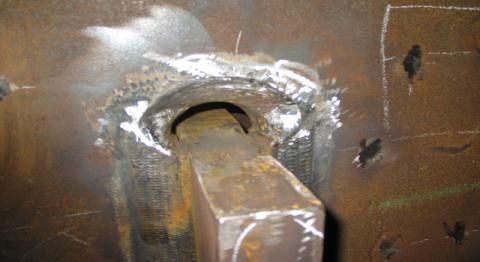
Figure 1 Pile 2 plate F upper opening with runoff tabs removed and surface ground
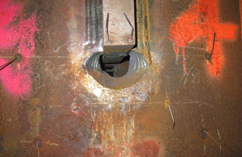
Figure 2 Pile 3 plate C with weld complete, runoff tabs removed at lower end and arc gouges evident as surface has not been ground
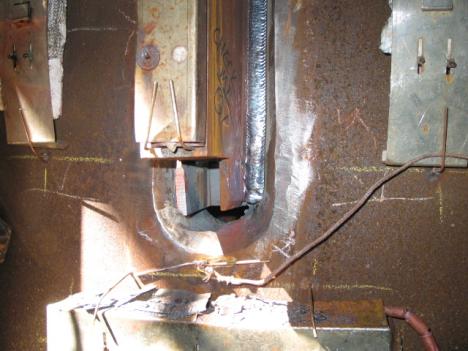
Figure 3 Pile 3 plate D showing runoff tabs and root pass at lower end of connection

Figure 4 Pile 3 plate D showing welding unit attached to pile sleeve with Buggo unit

Figure 5 Pile 3 plate G showing weld passes near upper end of shear connection plate
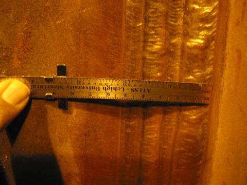
Figure 6 Pile 3 plate G showing weld passes of the cap weld
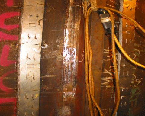
Figure 7 Pile 5 plate D showing regions of weld repair on the cap weld surface.
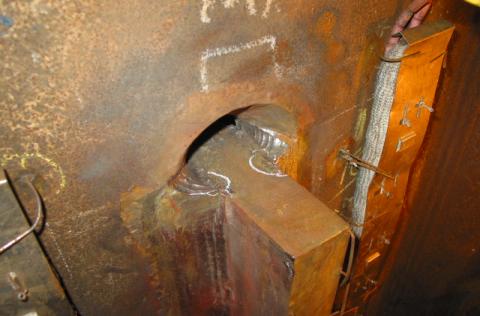
Figure 8 Pile 5 plate D at upper end showing MP indication at gouge which was removed by grinding. The weld ends have not been finished after runoff tab removal.