FHWA Bay Bridge Pile Connection Plate Welding Investigation
Background:
Certain welders alleged that they were instructed to deliberately hide weld defects from the inspectors by covering them with weld metal in certain partial joint penetration (PJP) welds joining the pile head connection plates to the pile sleeves. Each pier foundation typically consists of six (6) battered steel pile shells surrounded by a steel pile sleeve. The steel pile head connection plates are inserted into vertical slots in the pile shell and pile sleeve at eight locations per pile. PJP welds join the vertical pile head connection plates on both sides to the pile sleeve and the pile shell totaling 32 PJP's per pile, each with a nominal weld size of 35 mm. Weld joint preparation was reportedly such that the PJP welds were placed from inside the pile and inside the pile sleeve. Base metal for the pile sleeve and for the pile head connection plates is reported to be ASTM A709, Grade 345 (50). Reportedly the Contractor was ordered to stop work until the allegations were resolved. Two locations joining the pile head connection plate to the pile sleeve in Pier E4W have reportedly been identified as containing inferior quality weld metal. Welds joining the pile head connection plate to the pile shell have not been identified as inferior quality, and are not being evaluated at this time. Welding was reportedly done using the FCAWG weld process with a 90/10 mixture of Argon/CO2 shielding gas. Access to the far side of the PJP welds is extremely restricted. The annular space between the outside of the pile shell and the inside of the pile sleeve ranges between 100 mm and 250 mm. At this time, welding at Pier E4W is partially complete, and no grout or concrete fill has been placed.
Scope of Work:
Two independent companies, Mayes Testing Engineers, Inc. and Roy Teal, Inc. were contracted by the Federal Highway Administration (FHWA) to perform independent testing and evaluation of certain predefined weld locations at Pier E4W at the above project site. A document entitled Scope of Work and Services for Independent Testing at SFOBB – Skyway dated April 13, 2005 @12:32 pm was provided by the FHWA at the onset of assignment. The scope of work was redefined in an April 19, 2005 meeting held at the jobsite to assign certain responsibilities to each company, with Roy Teal, Inc. responsible for the following:
- Provide quality assurance duties representing the Federal Highway Administration during work done by Mayes Testing Engineers, Inc., including visual testing (VT) and Magnetic Particle Testing (MT) at the jobsite.
- Prepare a Weld Sample Removal Procedure for removal of base metal in pile sleeve E4W to preserve 100% of the adjacent weld material and adjacent heat affected zone at a minimum of three locations, two locations as determined by FHWA, and one location determined at random to serve as a baseline sample.
- Review the Specimen Testing and Tracking Procedure prepared by others.
- Supervise weld sample removal at the specified locations at the jobsite.
- Provide digital still photography to document typical welds, VT, MT and weld sample removal. The digital camera shall have a minimum resolution of 4.0 megapixels.
- Maintain Chain of Custody of weld samples, original video tapes and original digital still cards while at the jobsite.
- Review test results.
- Prepare a report of findings, including routine observations, unacceptable discontinuities, inspection procedures, evaluation in accordance with ANSI/AASHTO/AWS D1.5-96, conclusions, and a statement to verify whether contractual requirements for welding have been met.
- Provide an independent review of the QC-QA welding inspection process in Pier E5W when work is available. This is anticipated to occur at a later date.
- Prepare a report of the independent review of the QC-QA welding inspection for Pier E5W to include findings, inspection procedures, and conclusions to determine if the QC-QA procedures are adequate.
Summary Report
1) Planning
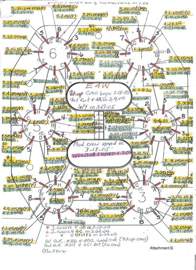
Several meetings were held with FHWA, Dr. John Fisher, CALTRANS, Mayes Testing Engineers, Inc., Mactech Engineering and Consulting, Inc. and Roy Teal, Inc. representatives to discuss methods of sampling and testing the weld metal in question. A decision was made to completely remove both PJP's joining the pile head connection plate to the pile sleeve, including the adjacent heat affected zones and pile head connection plate within one inch minimum from the weld fusion lines, as a single unit at three designated locations. A Weld Sample Removal Procedure (see Attachment A) was prepared and distributed to CALTRANS for issuance to the Contractor. The weld samples were determined to be removed from Pier E4W, pile head connection plate to pile sleeve locations 3G and 5D, which were both alleged to contain inferior quality welds. A baseline sample was randomly selected to be taken at location 2B. The designated locations are identified on CALTRANS quality assurance pile head connection plate location plan. (see Attachment B)
2) Independent VT and MT
Mayes Testing Engineers personnel performed visual inspection (VT) and magnetic particle testing (MT) at locations specified by FHWA. Pier E4W has eight (8) pile head connection plates, with two (2) PJP welds joining the pile shell and two (2) PJP welds joining the pile sleeve, for a total of thirty-two (32) PJP welds per pile head. Each PJP is 1700 mm long. Twenty-five percent (25%) of the total number of PJP welds (total length) were tested. This included all PJP welds to the pile sleeve at piles 2, 3 and 5, with exception of location 3G, which was not completely welded. MT was performed using the yoke technique in the AC output mode as described in Section 6 of ANSI/AASHTO/AWS D1.5-96, Bridge Welding Code. Many of the welds were work in progress at the time the Contractor stopped work. Several linear indications were found, removed by light grinding by MTE personnel and retested. No significant indications remained after completion of MT.
3) Quality Assurance VT
Roy Teal made a visual inspection of all PJP welds joining the pile head connection plates to the pile sleeve in piles 2, 3 and 5. In general, many of the welds were works in progress at the time the Contractor stopped work. As a result, surface profile irregularities were noted. Weld terminations were typically not completely prepared for testing and inspection at many locations. Heat tape pins remained at many locations. Several linear indications were found. These indications appeared to propagate from a failed PJP groove weld joining the run-off tab to the pile head connection plates at the top of the joint only. At weld sample locations 3G and 5D, the indications were removed by grinding, retested by MT, and determined that the indications were completely removed prior to weld sampling. Comments were made by on-site personnel that this type of indication was found at the top of many PJP weld joints, and that others were removed in a similar manner.
Based on visual inspection, no major, unacceptable discontinuities were found other than described above, when evaluated in accordance with Section 3 of ANSI/AASHTO/AWS D1.5- 96. There was no visual evidence of porosity, excessive undercut, excessive overlap, fusion discontinuities, or cracks other than the linear indications described.
4) Weld Sample Removal
Weld samples were removed by oxygen cutting by KFM personnel in accordance with the Weld Sample Removal Procedure issued by FHWA and a more detailed procedure following the prescribed guidelines and prepared by KFM. The Contractor prepared for sample removal by cutting existing mock-up weld joints in the on-site yard and establishing a detailed work procedure.
Work began by preheating prior to the start of each cut to 150 degrees F. The PJP weld joints were removed from the pile shell side of the pile head connection plate first, using an automatic oxygen cutting technique similar to that prescribed for the sample side. Similar procedures were used to remove the weld samples from the FHWA designated locations 2B, 3G and 5D. The weld samples were immediately marked for identification and orientation before leaving the removal site. The weld samples were then lifted out of the pile sleeves by come-a-long and crane, and placed in waiting wooden boxes.
5) Chain of Custody
After all three weld samples had been lifted from the pile sleeves to the waiting boxes, they were placed by crane on a waiting boat, and were accompanied during transportation to shore by Mr. Roland Nemis and Mr. Roy Teal.
The weld samples were then packaged for shipment, the wooden boxes nailed closed and placed in a waiting truck, all under the direct supervision of Mr. Nemis and Mr. Teal. The truck was padlocked by Mr. Nemis, and Chain of Custody letters were prepared for transferring the weld samples to Dwight Testing Laboratories under the care of Mayes Testing Engineers personnel.
6) Conclusions
Roy Teal, Inc. was requested to provide a quality assurance role while performing independent tests to determine the quality of partial joint penetration welds at specified locations in Pier E4W. Work was done on the specific weldments as presented. Confirmation of the welding processes used, actual welding parameters, prior quality control, prior quality assurance and prior nondestructive testing was not within the scope of work assigned at this time, and therefore was not done. The conclusions stated herein apply only to those locations specifically designated.
Based on general visual inspection of weldments at Pier E4W, and specifically the 47 partial joint penetration welds joining the pile head connection plates to the pile sleeve at piles 2, 3 and 5, I found that most welds, although incomplete at many locations, generally conformed to the quality requirements of ANSI/AASHTO/AWS D1.5-96, and therefore conformed to the quality requirements of the Contract documents. The welds were deemed incomplete, since they appear to be a work in progress when the Contractor stopped work at Pier E4W. In my opinion, minor weld profile blending and completion of grinding at the weld terminations would satisfy the quality provisions of the Contract documents. I found no evidence of major or unacceptable discontinuities, including porosity or fusion type discontinuities, in any of the weldments inspected. This visual inspection is supported by similar verbal results of magnetic particle tests performed independently by Mayes Testing Engineers, Inc.
In general, I have made casual observations of the Contractor's work habits, and noted that:
- Weld procedure specifications were posted at a conspicuous location near the weld site.
- The contractor provided a well thought out, thorough plan for removal of weld samples.
- The contractor, in our presence, perfected the sample removal procedure on a full size mockup inside a simulated pile and pile sleeve prior to beginning the work. This mock-up was reportedly used to perfect the welding procedure prior to beginning the work.
- The contractor conducted a meeting to discuss the weld sample removal plan with the workmen, which also included a hazard analysis and risk assessment, immediately prior to start of the weld sample removal.
- There did not appear to be any animosity among the workmen.
- The Contractor was cooperative, and responded positively to all requests.
Weld samples were successfully removed on April 22, 2005 as a single sample at the FHWA designated locations 2B, 3G and 5D. The samples were then shipped to Dwight Testing Laboratories for cutting and macroetch analysis.
Respectfully submitted,
![]()
| Roy Teal | May 3, 2005 |
Attachment A
San Francisco Oakland Bay Bridge PILE HEAD at PIER E4W
WELD SAMPLE REMOVAL PROCEDURE
- Select partial joint penetration (PJP) welds joining the pile head connection plate to the pile sleeve shall be sampled in accordance with the following procedure:
- No work shall begin until approved by FHWA or their designated representative.
- Removal of all specimens must be permanently marked using location designations currently used at the jobsite.
- Removal of specimens must be documented by video and digital still cameras as determined by FHWA.
- Each video segment shall include the date, time, location, photographer's name and personnel present.
- The video segment shall include a wide angle overview and close up of the area of interest.
- References such as rulers may be used to show relative scale.
- Still digital photography shall contain similar information in the picture or recorded in the photo log.
- Removed samples shall immediately be placed in the custody of the FHWA representative, and all handling, transfer for testing, packaging and shipping shall be thoroughly documented.
- All original documentation, including video and digital documents, must immediately be sent to the Mr. Krishna Verma, FHWA (HIBT-10).
- All cuts shall be made by thermal cutting as described in Section 3.2, Preparation of Base Metal, of the ANSI/AASHTO/AWS D1.5-96, Bridge Welding Code. Further, all cuts shall be carefully done to avoid damage to the entire partial joint penetration weld samples, the adjacent heat affected zones, and the base metal within ¼" of the weld fusion lines.
- Tabs may be welded to the outer edge only of the pile head connection plate to provide for removal of the weld sample. No other welding will be allowed.
- No work shall begin until approved by FHWA or their designated representative.
- PJP WELDS - PILE HEAD CONNECTION PLATE TO PILE SHELL:
- Thermally cut the existing PJP welds joining the pile head connection plate to the pile shell.
- These PJP welds are not intended to be sampled. Therefore, the cuts may be located as close as possible to the pile head connection plate to avoid damage to the pile shell.
- It is intended that the original slot and weld joint preparation be restored to its design dimensions by procedures approved by the CALTRANS Engineer.
- PJP WELDS - PILE HEAD CONNECTION PLATE TO THE PILE SLEEVE:
- Thermally cut adjacent to the existing PJP welds joining the pile head connection plate to the pile sleeve.
- Extreme care must be used to avoid damage to both full length weld samples, the adjacent heat affected zone (HAZ), and the base metal within ¼" of the weld toes.
- It is intended that the cuts be diagonal, parallel to the prior weld joint preparation in the pile sleeve, and that the entire length of both PJP welds, including the face, root and adjacent HAZ are preserved as a single, one piece sample.
- It is expected that the thermal cut will not continue into the pile head connection plate sufficient to remove the sample. See Step D.
- Slide the pile head connection plate toward the outside of the pile sleeve as necessary to make a full length cut to remove the sample.
- The location of the cut shall be at least 1" beyond the toe of the partial joint penetration weld reinforcement.
Attachment B: Pile Head Connection Plate Location Plan