U.S. Department of Transportation
Federal Highway Administration
1200 New Jersey Avenue, SE
Washington, DC 20590
202-366-4000
Federal Highway Administration Research and Technology
Coordinating, Developing, and Delivering Highway Transportation Innovations
 |
| This report is an archived publication and may contain dated technical, contact, and link information |
|
Publication Number: FHWA-HRT-05-056
Date: October 2006 |
|||||||||||||||||||||||||||||||||||||||||||||||||||||||||||||||||||||||||||||||||||||||||||||||||||||||||||||||||||||||||||||||||||||||||||||||||||||||||||||||||||||||||||||||||||||||||||||||||||||||||||||||||||||||||||||||
|
Previous | Table of Contents | Next Chapter 3, Compilation and Evaluation of Results From High-Performance Concrete Bridge Projects, Volume I: Final ReportAASHTO LRFD BRIDGE DESIGN SPECIFICATIONSThe compilation in this section is based on the AASHTO LRFD Bridge Design Specifications, Second Edition, 1998, and the 1999, 2000, and 2001 interim revisions.(7-10) This section only lists articles affected by HPC. For each listed article, the portion affected by HPC is shown in italics, followed by specific comments in regular font. For long articles, only a synopsis, followed by comments, is included. References in the comments to specific sections, articles, or tables refer to the document being reviewed and not the sections, articles, or tables of this report. The end result of the project is stated under the action item. Proposed revisions are included in appendix D. Research problem statements are included in appendix F. Section 5: CONCRETE STRUCTURES 5.1 SCOPE The provisions in this section apply to the design of bridge and retaining wall components constructed of normal density or lightweight concrete and reinforced with steel bars and/or prestressing strands or bars. The provisions are based on concrete strengths varying from 2.4 ksi to 10.0 ksi. The scope should be extended to concrete strengths higher than 70 MPa (10.0 kips/inch2 (ksi)). It should be made clear in the scope that welded wire reinforcement is included in this section. The scope should be expanded to include prestressing wire. Both welded wire reinforcement and prestressing wire have use in HPC. ACTION: Revisions to include welded wire reinforcement and design for strengths above 70 MPa (10.0 ksi) are proposed. 5.2 DEFINITIONS A definition of HPC should be included in this article to facilitate the introduction of provisions about HPC. ACTION: HPC concretes are proposed for the AASHTO LRFD Bridge Construction Specifications. Normal-Weight Concrete: Concrete having a weight between 0.135 and 0.155 kcf. The definition should be expanded for unit weights greater than 2.48 Mg/m3 (0.155 kips per cubic foot (kcf)), which can occur with HPC. ACTION: None. Existing data do not justify a revision. 5.3 Notation Since strengths are frequently specified at ages other than 28 days for HSC, rewording of this article should be considered. ACTION: A revision to delete 28 days is proposed. 5.4 MATERIAL PROPERTIES 5.4.1 GeneralC5.4.1Occasionally, it may be appropriate to use materials other than those included in the AASHTO LRFD Bridge Construction Specifications; for example, when concretes are modified to obtain very high strengths through the introduction of special admixtures, such as:
In these cases, the properties of such materials should be established by a specified testing program. Fly ash, ground granulated blast-furnace slag, and metakaolin should be added to the list of materials. The different test programs to achieve HPC should be defined. ACTION: A revision to include slag is proposed. 5.4.2 Normal and Structural Lightweight Concrete5.4.2.1 Compression StrengthConcrete strengths above 10.0 ksi shall be used only when physical tests are made to establish the relationships between concrete strength and other properties. The upper limit of 70 MPa (10.0 ksi) needs to be removed to the extent possible to permit the greater use of HSC. ACTION: A revision to remove the 70-MPa (10.0-ksi) restriction in specific articles is proposed. The sum of Portland cement and other cementitious materials shall be specified not to exceed 800 pcy. Although an upper limit may be appropriate for conventional strength concrete, it should be removed for HSC, which frequently contains more than 475 kg/m3 (800 lb/yd3) of cementitious materials. At the same time, excessive use of cementitious materials should be avoided. ACTION: A revision to increase the maximum cementitious materials content is proposed. Table C5.4.2.1-1 Concrete Mix Characteristics by Class This table needs to be extended to incorporate values for HPC. ACTION: Revisions to add two classes of HPC are proposed. 5.4.2.3 Shrinkage and Creep5.4.2.3.1 General In the absence of more accurate data, the shrinkage coefficients may be assumed to be 0.0002 after 28 days and 0.0005 after 1 year of drying. The final shrinkage strain differs significantly from the 28-day shrinkage strain. However, the final value, 0.0005, may not be appropriate for HPC. The AASHTO Standard Specifications uses a single number, 0.0002, for shrinkage strain. The conditions under which the stated shrinkage strains are applicable need to be defined. The appropriate values for HPC need to be determined. ACTION: Revisions based on NCHRP project 18-07 are proposed. 5.4.2.3.2 Creep and 5.4.2.3.3 Shrinkage These articles provide equations for the calculation of creep and shrinkage that are based on the recommendations of ACI Committee 209 as modified by additional published data. Depending on the constituents used to make HPC, the creep and shrinkage strain can be different from the values given by the equations. The equations need to be modified to include creep and shrinkage of HPC with its different constituent materials. Depending on the curing conditions for the concrete, the creep and shrinkage strain can vary. High early compressive strength is important for HSC to achieve early release of the pretensioning force. In most cases, this is achieved by applying heat or steam curing. This affects the creep of the concrete and needs to be included in the equation for creep strain. It is anticipated that information about creep will be developed as part of NCHRP project 18-07. This information will need to be incorporated into this article. ACTION: Revisions based on NCHRP project 18-07 are proposed. 5.4.2.4 Modulus of ElasticityIn the absence of more precise data, the modulus of elasticity, Ec, for concretes with unit weights between 0.090 and 0.155 kcf may be taken as:
where wc = unit weight of concrete (kcf)
Equation 5.4.2.4-1 for the modulus of elasticity may not be appropriate for HSC.(15) The stress-strain behavior of HPC is different than that for conventional strength concrete. There are data that suggest that the Ec for HSC may be influenced by aggregate stiffness.(26) Furthermore, some HSCs have a unit weight greater than 2.48 Mg/m3 (155 lb/ft3). Thus, the equation for Ec in this article needs to be evaluated using recent data. ACTION: A revision based on NCHRP project 18-07 is proposed. 5.4.2.6 Modulus of RuptureUnless determined by physical tests, modulus of rupture, fr, in ksi, may be taken as:
The factor in front of ACTION: Revisions for normal-weight concrete are proposed. A research problem statement is proposed for other weights of concrete. 5.4.2.7 Tensile StrengthC5.4.2.7For most regular concretes, the direct tensile strength may be
estimated as fr = 0.23 For HSC, a coefficient greater than 0.23 may be possible. ACTION: A research problem statement is proposed. 5.4.6 Ducts5.4.6.2 Size of DuctsThe size of ducts shall not exceed 0.4 times the least gross concrete thickness at the duct. With HSC precast concrete I-girders, thinner webs are often used to maximize section efficiency. Consideration should be given to allowing larger ducts in the webs of HSC members. ACTION: A revision to eliminate this provision for precast, pretensioned beams is proposed. 5.5 LIMIT STATES 5.5.3 Fatigue Limit State5.5.3.1 GeneralFatigue need not be investigated for concrete deck slabs in multigirder applications. With HSC girders and wider girder spacing, it may be necessary to investigate concrete deck slabs for fatigue. ACTION: None. The section properties for fatigue investigations shall be based on
cracked sections where the sum of stresses, due to unfactored
permanent loads and prestress, and 1.5 times the fatigue load is
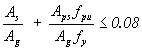
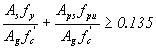
tensile and exceeds 0.095 The tensile stress limit in the last paragraph should be investigated for its applicability with HPC. ACTION: None. 5.5.4 Strength Limit State5.5.4.2 Resistance to Factors5.5.4.2.1 Conventional Construction Resistance factor
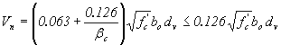
These resistance factors have been developed for conventional concrete. HPC tends to be very sensitive to water contents and constitutive materials. The chance of understrength concrete may increase, especially at very high compressive strength levels. On the other hand, HPC is produced with stricter quality control and a lower coefficient of variation than conventional concrete. Also, HSC has less lateral expansion than conventional strength concrete, so the effect of confinement is less. This affects column behavior. Therefore, there is a need to verify the suitability of the given resistance factors for HPC, especially HSC. ACTION: Revisions to include strength design for pretensioned concrete members at release are proposed. A research problem statement is proposed to address resistance factors. 5.6 DESIGN CONSIDERATIONS 5.6.3 Strut-and-Tie Model5.6.3.3 Proportioning of Compressive Struts5.6.3.3.3 Limiting Compressive Stress in Strut The limiting compressive stress, fcu , shall be taken as:
for which
where
The appropriateness of the limiting compressive stress should be verified for HSC. ACTION: A research problem statement is proposed. 5.6.3.5 Proportioning of Node RegionsUnless confining reinforcement is provided and its effect is supported by analysis or experimentation, the concrete compressive stress in the node regions of the strut shall not exceed:
The appropriateness of the maximum values of the concrete compressive stress in the node regions should be verified for HSC. ACTION: A research problem statement is proposed. 5.6.3.6 Crack Control ReinforcementStructures and components or regions thereof, except for slabs and footings, which have been designed in accordance with the provisions of Article 5.6.3, shall contain an orthogonal grid of reinforcing bars near each face. The spacing of the bars in these grids shall not exceed 12.0 inches. The ratio of reinforcement area to gross concrete area shall not be less than 0.003 in each direction. Since HSC has a higher tensile strength than conventional strength concretes, the minimum reinforcement ratio needs to increase as the concrete compressive strength increases. A revision to this article should be considered. ACTION: A research problem statement is proposed. 5.7 DESIGN FOR FLEXURAL AND AXIAL FORCE EFFECTS 5.7.1 Assumptions for Service and Fatigue Limit StatesThe following assumptions may be used in the design of reinforced, prestressed, and partially prestressed concrete components:
An effective modular ratio of 2n is applicable to permanent loads and prestress. The modular ratio of concrete is a function of modulus of elasticity of concrete, which is a function of the concrete compressive strength. HSC will frequently result in a modular ratio that is less than 6.0. Therefore, the validity of limiting the modular ratio, n, to 6.0 needs to be evaluated. Traditional methods of prestressed concrete design do not use an effective modular ratio of 2n for permanent loads and prestress. The validity of this article needs to be verified for HSC. ACTION: A revision to use the actual value of n is proposed. 5.7.2 Assumptions for Strength and Extreme Event Limit States5.7.2.1 GeneralFactored resistance of concrete components shall be based on the conditions of equilibrium and strain compatibility, the resistance factors as specified in Article 5.5.4.2, and the following assumptions:
This article defines the assumption for calculating flexural resistance of concrete members. An assessment should be made to determine if the maximum useable strain of 0.003 is applicable for HSC and if it is appropriate to assume any shape for the compressive stress-strain distribution. ACTION: None. Further research is the objective of NCHRP project 12-64. 5.7.2.2 Rectangular Stress DistributionThe natural relationship between concrete stress and strain may be
considered satisfied by an equivalent rectangular concrete
compressive stress block of 0.85 The stress-strain curve for HSC is more linear than for
conventional strength concrete. However, the stress block factors
are generally considered to be still valid for members where
flexure predominates. For members where axial compression
predominates, the concrete stress of 0.85 ACTION: None. Further research is the objective of NCHRP project 12-64. 5.7.3 Flexural Members5.7.3.1 Stress in Prestressing Steel at Nominal Flexural Resistance5.7.3.1.1 Components With Bonded Tendons For rectangular or flanged sections subjected to flexure about one axis where the approximate stress distribution specified in Article 5.7.2.2 is used and for which fpe is not less than 0.5 fpu, the average stress in prestressing steel, fps, may be taken as:
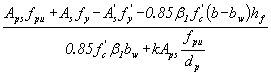
for which
for T-section behavior
for rectangular section behavior
The equations in this article are based on the assumption of a rectangular stress block as defined in article 5.7.2.2. If a different stress distribution is required for HSC, these equations may need to be revised or their application restricted to lower concrete strengths. The LRFD method relates Also, equation 5.7.3.1.1-1 of the LRFD provides prestressing steel stress at ultimate as a function of c. This requires iteration, since c is a function of fps. Combining equation 5.7.3.1.1-1 and equation 5.7.3.1.1-3, and by carrying on further mathematical manipulation, the equations can be written as follows:
or
These equations may considerably overestimate the neutral axis depth, c, and need to be evaluated for use with HSC. ACTION: None. Further research is the objective of NCHRP project 12-64. 5.7.3.2 Flexural Resistance5.7.3.2.2 Flanged Sections For flanged sections subjected to flexure about one axis and for biaxial flexure with axial load as specified in Article 5.7.4.5, where the approximate stress distribution specified in Article 5.7.2.2 is used and the tendons are bonded, and where the compression flange depth is less than c, as determined in accordance with Equation 5.7.3.1.1-3, the nominal flexural resistance may be taken as:
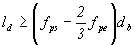
LRFD specifies a T-section behavior if c > hf. This is inconsistent with the traditional definition in the ACI 318 Building Code and the AASHTO Standard Specifications where a section is considered a T-section if a > hf . The impact of this article needs to be evaluated for use with HSC. ACTION: None. Further research is the objective of NCHRP project 12-64. 5.7.3.3 Limits for Reinforcement5.7.3.3.1 Maximum Reinforcement The maximum amount of prestressed and nonprestressed reinforcement shall be such that:
for which
The appropriateness of these equations for use with HSC needs to be evaluated. ACTION: None. Further research is the objective of NCHRP project 12-64. 5.7.3.3.2 Minimum Reinforcement Unless otherwise specified, at any section of a flexural component, the amount of prestressed and nonprestressed tensile reinforcement shall be adequate to develop a factored flexural resistance, Mr , at least equal to the lesser of:
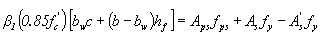
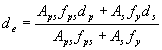
The provisions of Article 5.10.8 shall apply. The purpose of this article is to ensure that the section does not
go to the ultimate strength state as soon as it cracks. HSC is
known to have proportionately higher tensile strength than
conventional strength concrete. This means that the actual value of
cracking strength is higher that that calculated
using 0.24 ACTION: Revisions to article 5.4.2.6 are proposed. 5.7.3.6 Deformations5.7.3.6.2 Deflection and Camber Unless a more exact determination is made, the long-time deflection may be taken as the instantaneous deflection multiplied by the following factor:
HSC usually has lower creep than conventional strength concrete, so long-term deflection multipliers may be less. Long-term deflection factors were developed for conventional strength concrete and need to be verified for use with HSC. An approach similar to that of ACI 318 could be adopted.(18) However, the ACI factors may also need to be modified for use with HSC. ACTION: A research problem statement is proposed. 5.7.4 Compression Members5.7.4.2 Limits for ReinforcementThe maximum area of prestressed and nonprestressed longitudinal reinforcement for noncomposite compression components shall be such that:
and
The minimum area of prestressed and nonprestressed longitudinal reinforcement for noncomposite compression components shall be such that:
This article provides maximum and minimum reinforcement limits for compression members. These equations are different than those that appear in the AASHTO Standard Specifications. The limits given by these equations should be evaluated for use with HSC. ACTION: None. Further research is the objective of NCHRP project 12-64. 5.7.4.4 Factored Axial ResistanceThe factored axial resistance of reinforced concrete compressive components, symmetrical about both principal axes, shall be taken as:
for which
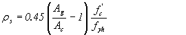
HSC has less lateral expansion than conventional strength concrete, so the confinement effect is less. This affects column behavior. The constants used in equations 5.7.4.4-2 and 5.7.4.4-3 need to be evaluated for use with HSC. ACTION: None. Further research is the objective of NCHRP project 12-64. 5.7.4.6 Spirals and TiesWhere the area of spiral and tie reinforcement is not controlled by:
the ratio of spiral reinforcement to total volume of concrete core, measured out-to-out of spirals, shall not be less than:
Spirals are less effective for confinement in HSC. Another formula is reported by ACI Committee 363 and should be considered.(15) In addition, the ratio of reinforcement required by equation 5.7.4.6-1 may be too high to be practical with HSC. The concept for providing spiral reinforcement to strengthen the core to offset the loss of strength when the concrete shell is lost may not be appropriate for HSC. ACTION: A research problem statement is proposed. 5.7.5 BearingIn the absence of confinement reinforcement in the concrete supporting the bearing device, the factored bearing resistance shall be taken as:
for which
The coefficient of 0.85 needs to be verified for HSC. ACTION: A research problem statement is proposed. 5.8 SHEAR AND TORSION 5.8.2 General Requirements5.8.2.2 Modifications for Lightweight ConcreteWhere lightweight aggregate concretes are used, the following modifications shall apply in determining resistance to torsion and shear:
Linear interpolation may be employed when partial sand replacement is used. The coefficients in front of ACTION: A research problem statement is proposed. 5.8.2.5 Minimum Transverse ReinforcementWhere transverse reinforcement is required, as specified in Article 5.8.2.4, the area of steel shall not be less than:
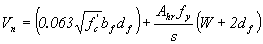
Equation 5.8.2.5-1 is similar to that developed for ACI 318 to allow for an increase in the minimum amount of shear reinforcement as concrete strength increases.(18) However, the coefficient in the ACI equation is 0.24. The appropriate coefficient for use with HSC needs to be determined. ACTION: None. Further research is being conducted under NCHRP project 12-56. 5.8.2.8 Design and Detailing RequirementsThe design yield strength of nonprestressed transverse reinforcement shall not exceed 60.0 ksi. The use of a design yield strength higher than 60.0 kips/inch2 should be considered for both HSC and conventional concretes. ACTION: Revisions to allow higher design yield strengths are proposed. 5.8.3. Sectional Design Model5.8.3.3 Nominal Shear ResistanceThe nominal shear resistance, Vn , shall be determined as the lesser of:
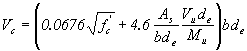
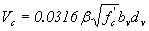
for which
This article provides a maximum limit on the nominal shear Vn. In equation 5.8.3.3-2, the presence of At higher compressive strengths, HSC is more brittle and the shear
cracks are smoother. As a result, there is less friction along the
shear cracks. Since this friction carries some of the shear load, shear provided by the concrete may be less. Consequently, the
constants 0.0316 and ACTION: None. Further research is being conducted under NCHRP project 12-56. 5.8.3.4 Determination of
| |||||||||||||||||||||||||||||||||||||||||||||||||||||||||||||||||||||||||||||||||||||||||||||||||||||||||||||||||||||||||||||||||||||||||||||||||||||||||||||||||||||||||||||||||||||||||||||||||||||||||||||||||||||||||||||||
|
(5.8.4.1-1)
[Equation 72] |
The nominal shear resistance used in the design shall not exceed:
|
(5.8.4.1-2)
[Equation 73] |
or
|
(5.8.4.1-3)
[Equation 74] |
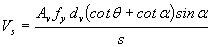
Reinforcement for interface shear between concretes of slab and beams or girders may consist of single bars, multiple-leg stirrups, or the vertical legs of welded wire fabric. The cross-sectional area, Avf , of the reinforcement per unit length of the beam or girder should not be less than either that required by Equation 1 or:
|
(5.8.4.1-4)
[Equation 75] (5.8.4.1-3) |
Equation 5.8.4.1-3 imposes a limit of 28 MPa (4000 psi) on the compressive strength of concrete that can be used in design. This limit needs to be evaluated based on recent test data.
Equation 5.8.4.1-4 should be changed so that the minimum reinforcement is a function of the concrete compressive strength.
ACTION: A research problem statement is proposed.
The following values shall be taken for cohesion factor, c, and
friction factor,  :
:
|
[Equation 76] |
|
[Equation 77] |
|
[Equation 78] |
|
[Equation 79] |
|
[Equation 80] |
|
[Equation 81] |
|
[Equation 82] |
|
[Equation 83] |
The following values shall be taken for  :
:
Tests have indicated that a smoother crack plane occurs with
HSC.(15) Consequently, the values of c,, and need to be evaluated for HSC.
ACTION: A research problem statement is proposed.
5.9 PRESTRESSING AND PARTIAL PRESTRESSING
5.9.4.1.1 Compression Stresses
The compressive stress limit for pretensioned and post-tensioned
concrete components, including segmentally constructed bridges, shall be 0.60  (ksi).
In article 9.15.2.1 of the AASHTO Standard Specifications, the
compressive stress limit for concrete at release for post-tensioned
members is 0.55  , compared to 0.60 in this
article. The use of 0.55 or 0.60 for HSC
should be assessed.
, compared to 0.60 in this
article. The use of 0.55 or 0.60 for HSC
should be assessed.
ACTION: Revisions to include strength design for pretensioned concrete members at release are proposed.
5.9.4.1.2 Tension Stresses
The limits in table 1 shall apply for tensile stresses.
Table 5.9.4.1.2-1. Temporary tensile stress limits in prestressed concrete before losses, fully prestressed components.
| Bridge Type | Location | Stress Limit |
|---|---|---|
|
Other Than Segmentally Constructed Bridges |
|
N/A |
|
0.0948  0.2 (ksi) 0.2 (ksi) |
|
|
0.22  (ksi) (ksi) |
|
|
0.158 (ksi) |
|
|
Segmentally Constructed Bridges |
Longitudinal Stresses Through Joints in Precompressed
Tensile Zone |
|
|
0.0948 maximum tension (ksi) |
|
|
No tension | |
|
0.100 ksi minimum compression | |
Transverse Stresses Through Joints |
||
|
(ksi) | |
Stresses in Other Areas |
||
|
No tension | |
|
0.19 |
|
HSC is known to have a proportionally higher tensile strength than conventional concrete. It may be possible to have higher stress limits in table 5.9.4.1.2-1.
ACTION: A research problem statement is proposed.
5.9.4.2.2 Tension Stresses
For service load combinations that involve traffic loading, tension stresses in members with bonded or unbonded prestressing tendons should be investigated using Load Combination Service III specified in table 3.4.1-1. The limits in table 1 shall apply.
Table 5.9.4.2.2-1. Tensile stress limits in prestressed concrete at service limit state after losses, fully prestressed components.
| Bridge Type | Location | Stress Limit |
|---|---|---|
|
Other Than Segmentally Constructed Bridges |
Tension in the Precompressed Tensile Zone Bridges, Assuming Uncracked Sections | |
|
0.19  (ksi) (ksi) |
|
|
0.0948 (ksi) |
|
|
For components with unbonded prestressing tendons. |
No tension | |
|
Segmentally Constructed Bridges |
Longitudinal Stresses Through Joints in the Precompressed Tensile Zone | |
| Type A joints with minimum bonded auxiliary reinforcement through the joints sufficient to carry the calculated longitudinal tensile force at a stress of 0.5 fy , internal tendons. | ||
| Type A joint without the minimum bonded auxiliary reinforcement through joints. | No tension | |
|
Type B joints, external tendons. |
0.100 ksi minimum compression | |
| Transverse Stresses Through Joints | ||
|
0.0948 | |
| Stresses in Other Areas | ||
| For areas without bonded reinforcement. | No tension | |
|
Bonded reinforcement sufficient to carry the calculated tensile force in the concrete computed on the assumption of an uncracked section at a stress of 0.5 fsy. |
0.19 |
|
HSC is known to have a proportionally higher tensile strength than conventional concrete. It may be possible to have higher stress limits in table 5.9.4.2.2-1.
ACTION: A research problem statement is proposed.
An approximate lump sum estimate of time-dependent prestress losses resulting from creep and shrinkage of concrete and relaxation of steel in prestressed and partially prestressed members may be taken as specified in table 1 for:
Pretensioned members stressed after attaining a compressive
strength = 3.5 ksi, provided that
Table 5.9.5.3-1. Time-dependent losses in ksi.
| Type of Beam Section | Level | For Wires and Strands Withfpu = 235, 250, or 270 ksi | For Bars With fpu = 145 or 160 ksi |
|---|---|---|---|
|
Rectangular Beams, Solid Slab |
Upper Bound Average |
29.0 + 4.0 PPR |
19.0 + 6.0 PPR |
Box Girder |
Upper Bound Average |
21.0 + 4.0 PPR
|
15.0 |
I-Girder |
Average |
33.0 PPR |
19.0 + 6.0 PPR |
|
Single-T, Double-T, Hollow Core, and Voided Slab |
Upper Bound Average |
39.0 PPR 33.0 PPR |
31.0 PPR |
The equations in this article are based on parametric studies for a limited range of ultimate creep and shrinkage coefficients. Generally, HSC has lower creep and similar shrinkage values relative to conventional strength concrete. In table 5.9.5.3-1, the equations do not reflect the higher prestress levels used with HSC. The lump-sum equations may need to be evaluated for use with HSC.
NCHRP project 18-07 has the objective of developing design guidelines for estimating prestress losses in pretensioned HSC bridge girders. Results of the NCHRP project need to be incorporated into this article.
ACTION: Revisions to articles 5.9.5.1, 5.9.5.2, and 5.9.5.3 based on NCHRP project 18-07 are proposed.
5.9.5.4.1 General
More accurate values of creep-, shrinkage-, and relaxation-related losses than those specified in Article 5.9.5.3 may be determined in accordance with the provisions of either Article 5.4.2.3 or this article for prestressed members with:
For lightweight concrete, loss of prestress shall be based on the representative properties of the concrete to be used.
Equations are then provided for calculation of individual components of prestress losses.
Results of NCHRP project 18-07 will need to be incorporated into this article.
ACTION: Revisions based on NCHRP project 18-07 are proposed.
5.10 DETAILS OF REINFORCEMENT
5.10.11.4.1d Transverse Reinforcement for Confinement at Plastic Hinges
The cores of columns and pile bents shall be confined by transverse reinforcement in the expected plastic hinge regions. The transverse reinforcement for confinement shall have a yield strength not more than that of the longitudinal reinforcement, and the spacing shall be taken as specified in Article 5.10.11.4.1e.
For a circular column, the volumetric ratio of spiral
reinforcement, ![]() s, shall not be less than either that
required in Article 5.7.4.6 or:
s, shall not be less than either that
required in Article 5.7.4.6 or:
|
(5.10.11.4.1d-1)
[Equation 84] |
For a rectangular column, the total gross sectional area, Ash, of rectangular hoop reinforcement shall not be less than either:
|
(5.10.11.4.1d-2)
[Equation 85] |
or
|
(5.10.11.4.1d-3)
[Equation 86] |
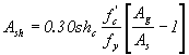
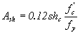
The volumetric ratio of spiral reinforcement and the total gross sectional area of rectangular hoop reinforcement required by equations 5.10.11.4.1d-1 and 5.10.11.4.1d-2, respectively, may be too high to be practical with HSC. The concept of providing reinforcement to strengthen the core to offset the loss of strength when the concrete shell is lost may not be appropriate for HSC.
ACTION: A research problem statement is proposed.
5.10.11.4.2 Requirements for Wall-Type Piers
The factored shear resistance, Vr, in the pier shall be taken as the lesser of:
|
(5.10.11.4.2-1) [Equation 87] |
and
|
(5.10.11.4.2-2)
[Equation 88] |
for which
|
(5.10.11.4.2-3)
[Equation 89] |
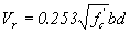
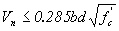
Equations 5.10.11.4.2-1 and 5.10.11.4.2-3 should be evaluated for use with HSC.
ACTION: A research problem statement is proposed.
5.10.11.4.3 Column Connections
The nominal shear resistance, provided by the concrete in the joint of a frame or bent in the direction under consideration, shall not exceed:
|
(5.10.11.4.3-1)
[Equation 90] |
|
(5.10.11.4.3-2)
[Equation 91] |
Equations 5.10.11.4.3-1 and 5.10.11.4.3-2 should be evaluated for use with HSC.
ACTION: A research problem statement is proposed.
5.11 DEVELOPMENT AND SPLICES OF REINFORCEMENT
5.11.2.1.1 Tension Development Length
The tension development length, ld, shall not be less than the product of the basic tension development length, ldb, specified herein and the modification factor or factors specified in Articles 5.11.2.1.2 and 5.11.2.1.3. The tension development length shall not be less than 12.0 inches, except for lap splices specified in Article 5.11.5.3.1 and development of shear reinforcement as specified in Article 5.11.2.6
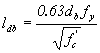
The basic tension development length, ldb, in inches, shall be taken as:


This article contains provisions for the development length of reinforcement based on the provisions of ACI 318-89. These were extensively modified in the ACI 318-95 provisions, with a view toward formulating a more user-friendly format while maintaining the same general agreement with research results and with professional judgment. Limited tests have indicated that the development lengths calculated using the above provisions are applicable to HSC.(29) However, the tests resulted in a more sudden failure than occurs with conventional strength concrete. Consideration should be given to adopting similar provisions as ACI 318-95 after the development lengths have been verified for HSC.
ACTION: None. Further work is the objective of NCHRP project 12-60.
5.11.2.1.2 Modification Factors That Increase ld
The basic development length, ldb, shall be multiplied by the following factor or factors, as applicable:
Linear interpolation may be used between all-lightweight and sand-lightweight provisions when partial sand replacement is used.
The product obtained when combining the factor for top reinforcement with the applicable factor for epoxy-coated bars need not be taken to be greater than 1.7.
5.11.2.1.3 Modification Factors That Decrease ld
The basic development length, ldb, modified by the factors as specified in Article 5.11.2.1.2, may be multiplied by the following factors, where:
The above factors need to be verified for HPC.
ACTION: None. Further work is the objective of NCHRP project 12-60.
5.11.2.2.1 Compressive Development Length
The development length, ld, for deformed bars in compression shall not be less than either the product of the basic development length specified herein and the applicable modification factors specified in Article 5.11.2.2.2 or 8 inches.
The basic development length, ldb, for deformed bars in compression shall not be less than:
|
(5.11.2.2.1-1)
[Equation 92] |
or
|
(5.11.2.2.1-2)
[Equation 93] |
5.11.2.2.2 Modification Factors
The basic development length, ldb, may be multiplied by applicable factors, where:
The above factors need to be verified for HPC.
ACTION: None. Further work is the objective of NCHRP project 12-60.
The development length of individual bars within a bundle, in tension, or compression shall be that for the individual bar, increased by 20 percent for a three-bar bundle and by 33 percent for a four-bar bundle.
For determining the factors specified in Articles 5.11.2.1.2 and 5.11.2.1.3, a unit of bundled bars shall be treated as a single bar of a diameter determined from the equivalent total area.
The above factors need to be verified for HPC.
ACTION: None. Further work is the objective of NCHRP project 12-60.
5.11.2.4.1 Basic Hook Development Length
The development length, ldh, in inches, for deformed bars in tension terminating in a standard hook specified in Article 5.10.2.1 shall not be less than:
Basic development length, lhb, for a hooked bar with yield strength, fy, not exceeding 60.0 ksi shall be taken as:
|
(5.11.2.4.1-1)
[Equation 94] |
The above factors need to be verified for HPC.
ACTION: None. Further work is the objective of NCHRP project 12-60.
5.11.2.4.2 Modification Factors
Basic hook development length, lhb, shall be multiplied by the following factor or factors, as applicable, where:

All provisions of article 5.11.2.4 need to be verified for HPC.
ACTION: None. Further work is the objective of NCHRP project 12-60.
5.11.2.5.1 Deformed Wire Fabric
For applications other than shear reinforcement, the development length, lhd, in inches, of welded deformed wire fabric, measured from the point of critical section to the end of wire, shall not be less than either:
5.11.2.5.2 Plain Wire Fabric
The yield strength of welded plain wire fabric shall be considered developed by embedment of two cross wires with the closer cross wire not less than 2.0 inches from the point of critical section. Otherwise, the development length, ld, measured from the point of critical section to outermost cross wire shall be taken as:
|
(5.11.2.5.2-1)
[Equation 95] |
The development length shall be modified for reinforcement in excess of that required by analysis as specified in Article 5.11.2.4.2, and by the factor for lightweight concrete specified in Article 5.11.2.1.2, where applicable. However, ld shall not be taken to be less than 6.0 inches, except for lap splices, as specified in Article 5.11.6.2.
All provisions of article 5.11.2.5 need to be verified for HPC.
ACTION: None. Further work is the objective of NCHRP project 12-60.
For the purposes of this article, the transfer length may be taken as 60 strand diameters and the development length shall be taken as specified in Article 5.11.4.2.
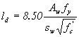
5.11.4.2 BONDED STRAND
Pretensioning strand shall be bonded beyond the critical section for development length, in inches, taken as:
|
(5.11.4.2-1)
[Equation 96] |
This article contains general requirements for the transfer and development lengths of prestressing strand. It is defined in the article that the transfer length for pretensioned prestressing strand may be taken as 60 strand diameters. This value is increased from the 50 diameters used in the AASHTO Standard Specifications,article 9.20.2.4. A lower transfer length is possible for HPC. These provisions should be evaluated for HSC. Researchers at FHWA have suggested new equations for transfer and development lengths of bonded prestressing strand.(30) Those equations should be reviewed for their appropriateness with HSC.
ACTION: None. Further work is the objective of NCHRP project 12-60.
5.11.5.3.1 Lap Splices in Tension
The length of lap for tension lap splices shall not be less than either 12.0 inches or the following for Class A, B, or C splices:
Class A
splice.....................................................................................................
1.0 ld
Class B
splice.....................................................................................................
1.3 ld
Class C
splice....................................................................................................
1.7 ld
The tension development length, ld, for the specified yield strength shall be taken in accordance with Article 5.11.2.
The class of lap splice required for deformed bars and deformed wire in tension shall be as specified in table 1.
Table 5.11.5.3.1-1. Classes of tension lap splices.
| Ratio of |
Percent of As Spliced With Required Lap Length | ||
|---|---|---|---|
| 50 | 75 | 100 | |
 2 2 |
A |
A |
B |
< 2 |
B |
C |
C |
All provisions of article 5.11.5 need to be verified for HPC.
ACTION: None. Further work is the objective of NCHRP project 12-60.
5.12 DURABILITY
The contract documents shall prohibit the use of aggregates from sources that are known to be excessively alkali-silica reactive.
If aggregate of limited reactivity is used, the contract documents shall require the use of either low-alkali-type cements or a blend of regular cement and pozzolanic materials, provided that their use has been proven to produce concrete of satisfactory durability with the proposed aggregate.
For HPC, testing should be conducted or field experience should be used to determine if a given source of aggregate can be safely used with specific cementitious materials.
ACTION: Revisions referencing AASHTO M 6 and M 80 are proposed.
Cover for unprotected prestressing and reinforcing steel shall not
be less than that specified
in table 1 and modified for the W/C ratio, unless otherwise
specified either herein or in Article 5.12.4.
Concrete cover and placing tolerances shall be shown in the contract documents.
Cover for pretensioned prestressing strand, anchorage hardware, and mechanical connections for reinforcing bars or post-tensioned prestressing strands shall be the same as for reinforcing steel.
Cover for metal ducts for post-tensioned tendons shall not be less than:
For decks exposed to tire studs or chain wear, additional cover shall be used to compensate for the expected loss in depth due to abrasion, as specified in Article 2.5.2.4.
Modification factors for the W/C ratio shall be the following:
0.40.........................................................................................
0.8 0.50.........................................................................................
1.2Minimum cover to main bars, including bars protected by epoxy coating, shall be 1.0 inch.
Cover to ties and stirrups may be 0.5 inch less than the values specified in table 1 for main bars, but shall not be less than 1.0 inch.
This article provides minimum cover requirements for a range of exposure conditions. HPC is less permeable than conventional concrete, and a longer service life is expected.
The second bullet after the fourth paragraph that says “One-half the diameter of the duct” should be revised to allow the use of wider ducts in 152-mm- (6-inch-) thick webs.
In this article, modification factors for w/c ratios of 0.40 and 0.50 are given. A gradual transition would be more logical. Furthermore, there are ways to reduce the permeability without lowering the w/c ratio.
ACTION: None.
5.13 SPECIFIC MEMBERS
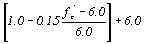
5.13.2.4.2 Alternative to Strut-and-Tie Model
|
(5.13.2.4.2-1) [Equation 97] |
and
|
(5.13.2.4.2-2) [Equation 98] |
|
(5.13.2.4.2-3) [Equation 99] |
or
|
(5.13.2.4.2-4) [Equation 100] |
Equations 5.13.2.4.2-1 and 5.13.2.4.2-2 impose a limit of 28 MPa (4.0 ksi) on the compressive strength of concrete that can be used in design. The limits of equation 5.13.2.4.2-2 and 0.2 fc’ need to be evaluated for HSC.
ACTION: A research problem statement is proposed.
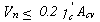
5.13.2.5.4 Design for Punching Shear
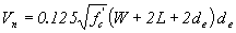
Nominal punching shear resistance, Vn, in kips, shall be taken as:
|
(5.13.2.5.4-1)
[Equation 101] |
|
(5.13.2.5.4-2)
[Equation 102] |
The equations in this article should be verified for use with HSC.
ACTION: A research problem statement is proposed.
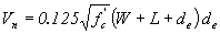
5.13.2.5.5 Design of Hangar Reinforcement
Using the notation in Figure 2, the nominal shear resistance of the ledges of inverted T-beams shall be the lesser of that specified by Equation 2 and Equation 3.
|
(5.13.2.5.5-3) [Equation 103] |
Equation 5.13.2.5.5-3 should be verified for use with HSC.
ACTION: A research problem statement is proposed.
5.13.3.6.3 Two-Way Action
For two-way action for sections without transverse reinforcement, the nominal shear resistance, Vn, in kips, of the concrete shall be taken as:
|
(5.13.3.6.3-1) [Equation 104] |
For two-way action for sections with transverse reinforcement, the nominal shear resistance,
Vn, in kips, shall be taken as:
|
(5.13.3.6.3-2) [Equation
105] |
for which
|
(5.13.3.6.3-3)
[Equation 106] |
and
|
(5.13.3.6.3-4)
[Equation 107] |
The equations in this article should be verified for use with HSC.
ACTION: A research problem statement is proposed.
5.13.4.4.1 Pile Dimensions
The wall thickness of cylinder piles shall not be less than 5.0 inches.
A wall thickness of less than 127 mm (5.0 inches) should be allowed when HPC is used.
ACTION: A revision to eliminate the minimum wall thickness is proposed.
5.14 PROVISIONS FOR STRUCTURE TYPES
5.14.1.2.5 Concrete Strength
For slow-curing concretes, the 90-day compressive strength may be used for all stress combinations that occur after 90 days.
For normal-weight concrete, the 90-day strength of slow-curing concretes may be estimated at 115 percent of their 28-day strength.
This article is very relevant to HSC. It should be revised to clarify the meaning of slow-curing concrete and allow the use of 56-day strengths. The factor of 115 percent should be evaluated based on data from the FHWA HPC showcase bridges.
ACTION: A research problem statement is proposed.
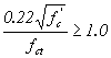
15.4.2.3.3 Construction Load Combinations at the Service Limit State
Tensile stresses in concrete due to construction loads shall not
exceed the values specified in table 1; except for structures with
Type A joints and less than 60 percent of their tendon capacity
provided by internal tendons, the tensile stresses shall not exceed 0.095 . For structures with Type B joints, no tensile stresses
shall be permitted.
HSC has a relatively higher tensile strength than conventional strength concrete. The tensile stress limit in this article and in table 5.14.2.3.3-1 should be evaluated for HSC.
ACTION: A research problem statement is proposed.
5.14.2.4.7 Precast Segmental Beam Bridges
5.14.2.4.7b Segment Reinforcement
Segments of segmental beam bridges shall preferably be pretensioned
for dead load and all construction loadings to limit the tensile
stress in the concrete to 0.0948 .
The tensile stress limit should be evaluated for use with HSC.
ACTION: A research problem statement is proposed.
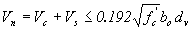
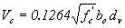
|
(5.14.5.3-1)
[Equation 108] |
but Vc shall not exceed 0.126 bde.
Although HSC may not be used in slabs for box culverts, the limits for Vc in this article should be evaluated for use with HSC.
ACTION: A research problem statement is proposed.
Section 9: Decks and Deck Systems
This section contains provisions for the analysis and design of
bridge decks and deck systems
of concrete, metal, and wood, or combinations thereof, subject to
gravity loads. No provisions affected by HPC were identified in the
section.
ACTION: None.
Section 8 of the AASHTO LRFD Bridge Construction Specifications deals with concrete structures. The technical provisions are essentially the same as those in the AASHTO Standard Specifications for Highway Bridges, Division II, Section 8, Concrete Structures, except for the use of metric units in the LRFD version. Consequently, a separate review of the LRFD specifications was not undertaken. Proposed revisions to the AASHTO LRFD Specifications, similar to those proposed for division II, section 8 of the AASHTO Standard Specifications, are included in appendix D. The proposed revisions are based on AASHTO LRFD Bridge Construction Specifications, First Edition, 1998, and the 1999, 2000, and 2001 interim revisions.(11-14)
Previous | Table of Contents | Next
FHWA-HRT-05-056


 shall be taken as:
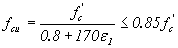

 s = the smallest angle between the compressive strut
and adjoining tension ties (deg.)
s = the smallest angle between the compressive strut
and adjoining tension ties (deg.) s = the tensile strain in the concrete in the direction
of the tension tie (inches/inch)
s = the tensile strain in the concrete in the direction
of the tension tie (inches/inch)


 need to be verified for both
all-lightweight concrete and sand-lightweight HPC.
need to be verified for both
all-lightweight concrete and sand-lightweight HPC.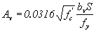


 and
and  using equations, tables, and figures. The equations, tables, and figures were developed considering


 PPR
PPR