U.S. Department of Transportation
Federal Highway Administration
1200 New Jersey Avenue, SE
Washington, DC 20590
202-366-4000
Federal Highway Administration Research and Technology
Coordinating, Developing, and Delivering Highway Transportation Innovations
 |
| This report is an archived publication and may contain dated technical, contact, and link information |
|
Publication Number: FHWA-HRT-07-036 Date: March 2007 |
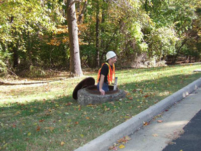
Junction Loss Experiments: Laboratory ReportCHAPTER 1. INTRODUCTIONBACKGROUNDStorm drains generally collect storm runoff from streets, parking lots, and other structures and convey this water to a desired outfall. Access holes (or manholes), which allow staff to inspect, maintain, or repair a segment of the drainage, are usually spaced about 92 to 183 meters (m) (300 to 600 feet (ft)) apart along a given pipe and at every junction between multiple pipes. An access hole, which has at least one inlet pipe and one outlet pipe intersecting it, is usually constructed from a vertically oriented concrete pipe or box that is large enough for a person to enter by removing the cast iron lid and using a ladder (see figure 1). In addition to allowing access, access hole junctions also allow pipes to easily change one or more variables: direction, slope, diameter, and elevation.
Figure 1. Photo. Typical access hole. Estimating the energy loss associated with these access hole junctions is a critical step in designing a drainage network that can handle the incoming flow from various storm events (see figure 2). Between 1986 and 1992, Chang et al. conducted a lab study of energy losses through junction access holes, using relatively large-scale (one-quarter scale) physical models.(1) A preliminary method for determining such losses, based on early results from that study, was published in the Federal Highway Administration's (FHWA) Urban Drainage Design Manual (Hydraulic Engineering Circular No. 22 (HEC 22)).(2) A revised method, based on the final results, was coded in the highway drainage (HYDRAIN) software system.(3)
Figure 2. Diagram. Cross-section definition sketch of an access hole. Practitioners questioned both of these methods when they encountered situations beyond the range of the experimental parameters tested in the lab study. They found that these methods have limitations when applied to junctions with plunging inflow and to junctions with outflow pipes that carry supercritical flow. These methods are also relatively complex and require iterative solutions. A criticism of both the HEC 22 and HYDRAIN approaches is that they use the same loss coefficient for different flow conditions.(2,3) These issues ultimately motivated the FHWA to reanalyze the old lab data. Roger Kilgore of Kilgore Consulting and Management, who was the principal investigator in this effort, developed a new method that classifies access holes and their hydraulic conditions in a manner similar to the way that culverts are classified as "inlet controlled" or "full flow." The primary hypothesis of this method is that the energy loss coefficient should be a function of the basic flow conditions in an access hole. The result is a new method, which is somewhat simpler than the existing methods and might improve handling of plunging flow and supercritical flow situations. Kilgore initially tested his new method using the 1986–1992 lab data by separating the data into two groups. The first group consisted of "base runs" with the simplest configurations (one inflow and one outflow pipe with the same base elevations) to establish first approximations of the energy loss across an access hole. The second group included the more complex lab configurations entailing benching, angled inflows, and plunging inflows. Kilgore used the second group of experiments to derive adjustments to the first approximations. All of the theory behind these approximations will be given in the theory section later in this report. Kilgore's analysis of the old lab data, however, was concurrently supplemented with additional lab experiments conducted by the FHWA Hydraulics Laboratory. This report summarizes the additional experiments and the data collected and used to evaluate the new junction loss methodology. PROBLEMThe previous research was limited to relatively flat storm drain systems. The results were presented as empirical equations that were not readily understood from intuitive reasoning, and the methods in HEC-22 and in the HYDRAIN computer program were not consistent.(2,3) For these reasons, the research in this report has two main objectives. The first is to evaluate the proposed junction loss method by conducting new tests that are very similar to the previous study. The new tests, however, include a wider range of parameters, such as greater plunge-height ratios and steeper pipe slopes. The second and more challenging objective is to characterize the energy level in an access hole with various inflow and outflow pipe configurations using local measurements of velocity and pressure head. Characterizing the energy level in an access hole is highly problematic because the flow is so chaotic, and a certain degree of trial and error is required to interpret the laboratory data in a way that practitioners will find useful. This new laboratory data was shared with Kilgore, who subsequently modified part of his methodology to accommodate the new results. The FHWA and Kilgore agreed on the following experiments to evaluate his proposed procedure.
|