U.S. Department of Transportation
Federal Highway Administration
1200 New Jersey Avenue, SE
Washington, DC 20590
202-366-4000
Federal Highway Administration Research and Technology
Coordinating, Developing, and Delivering Highway Transportation Innovations
 |
| This report is an archived publication and may contain dated technical, contact, and link information |
|
Publication Number: FHWA-RD-97-146 Date: NOVEMBER 1997 |
Acid-igneous rocks. Igneous rocks that are rich in quartz and the potassium sodium feldspars. May contain mica, amphibole, etc. Examples are granite and granodiorite. These rocks are often light colored and/or mottled. It is common (except in extrusive volcanic rocks) for the individual grains to be large enough to be easily distinguished by the unaided eye.
Alkali-aggregate reaction. Any potentially expansive chemical reaction between the aggregate and the hydroxide ions associated with the ions of sodium and potassium in solution in the paste. Can be very deleterious (see alkali-carbonate reaction and alkali-silica reaction).
Alkali-carbonate reaction. A potentially expansive chemical reaction between a carbonate aggregate and the hydroxide ions associated with the ions of sodium and potassium in solution in the paste. The only rock known to so react is an impure dolomitic limestone with a specific internal structure. Can be very deleterious if the forces generated by the reaction exceed the cohesive forces of the concrete. See Chapter 10.
Alkali-silica reaction. A potentially expansive chemical reaction between siliceous aggregate and the hydroxide ions associated with the ions of sodium and potassium in solution in the paste. The siliceous rocks involved in this reaction are those with an imperfect crystal structure or those that are not crystalline. Can be very deleterious if the forces generated by the expanding silica gels exceed the cohesive forces of the placement. Deteriorated HCC often exhibits oozing silica gels or the dehydrated and carbonated remains of silica gels. See Chapter 10.
Amorphous. Not crystalline; without a regular arrangement of the component atoms into a crystal structure.
Analyzer. In a petrographic microscope, a device (located above the objective) that polarizes the light after it has passed through the specimen.
Anhedral. Without bounding crystal faces. Cf. euhedral, subhedral.
Basic-igneous rocks. Igneous rocks that are rich in the sodium-calcium feldspars, with little or no quartz; often abundant olivine and pyroxenes. Examples are basalts and diorites. These rocks are often very dark colored and fine grained.
Becke line. In the microscopical test for the relative index of refraction, a bright line that is most visible while in motion as the focus is changed. It is the projection of the boundary of two substances of different indices of refraction. If the match between the indices is close, the line may be refracted into rainbow colors (unless monochromatic light is used). As the objective lens is raised from the subject, the Becke line appears to move toward the center of the substance with a higher index of refraction. If the line is refracted into colors, the position (movement) of the rusty red color is taken as the true position.
Beneficiation. The process of improving the chemical properties, physical properties, or both of an ore or other earth material for use in a manufacturing process or as a construction material.
Bertrand lens. A removable plano-convex lens on a slide located in the tube of a petrographic microscope above the upper nicol (analyzer); used with convergent light from the condenser to form interference figures and thus determine the number of optic axes and the optical sign. The focusable, diaphragmed Bertrand lenses are the most convenient.
Binocular. Pertaining to optical equipment. Allowing the use of both eyes together either to permit the sensation of relative distance (when two objective lenses are furnished) or provide a more natural method of viewing the subject. In modern petrographic microscopes, binocular viewing is present to relieve eye strain and cannot provide a sensation of depth. In many microscopes, the prisms necessary to split the image for use by both eyes may make determinations of the properties of the optic axis figures nearly impossible.
Biotite. A dark-colored mineral of the mica group that exhibits excellent platy cleavage; in thin section, a bird's eye texture and a birefringence of 0.033.
Birefringence. The numerical difference in the index of refraction between two rays of light separated from one light source by the properties of the substance. Birefringence can be observed when a nonisotropic substance is placed between crossed nicols. The diffraction colors seen are a product of the birefringence of the substance and its thickness. Also called double refraction. Low birefringence is gray though pale white, 0.005; moderate birefringence includes the first order colors up to 0.030; all above 0.030 is high to very high.
Birefringent. The property of having at least a minimal birefringence.
Bleed water. The water produced by bleeding (q.v.). The water can be seen as a wet sheen on the surface of the concrete. When abundant, it can form puddles.
Bleeding. In the hardening of concrete, a process whereby the solids of the HCC, including the cement and other fine particles, settle and water rises to the top. (Has been thought to be caused by syneresis but is probably almost entirely due to settlement.)
Calcite. Calcium carbonate, CaCO3, a common mineral and a major ingredient of limestones and certain other sedimentary rocks. Often occurs as a vein mineral. Calcite is colorless or white when pure, crystallizes in the rhombohedral class, has a hardness of 3 on the Mohs scale, and dissolves with the effervescence of carbon dioxide in dilute hydrochloric acid. The transparent forms of calcite exhibit excellent double refraction that can be observed in thick slices without lenses or polarizers. The carbonates have a very high birefringence; calcite = 0.172. Cf. dolomite.
Carbonation. The process in portland cement concrete and in other HCCs where the calcium ions in solution or in the calcium silicate hydrates react with the carbon dioxide of the atmosphere, in the presence of moderate humidity, and become changed to calcium carbonate with impurities such as amorphous silica. On the surface of HCC, the production of calcium carbonate by this method can provide a tough surface. In the interior, it can indicate weakness; passageways for water, air, and CO2 to enter the paste; and lowered pH of the paste, thus making the steel more susceptible to corrosion. See depassivation. (Not to be confused with the carbonation of soda water or the coalification of organic materials.)
Cold joint. A joining between two adjacent placements of HCC material where the earlier placement had hardened when the second was placed. May indicate little or no bond between the two concretes.
Collimate. When pertaining to light rays, to make parallel.
Conchoidal. Said of a fracture surface that is made up of smoothly curved, shell- like surfaces. True of quartz and obsidian and other massive glasses.
Conoscopic lenses. The lenses used to form interference figures. See Bertrand lens.
Core. When pertaining to concrete testing, a specimen cut from a hardened placement or a large block of concrete with a diamond core drill for use as a portion of the material for various testing procedures. It is preferred that the core drill have an internal diameter of at least 4 in. The core should be as deep as the placement is thick so that the entire thickness of the placement is sampled. When coring bridge decks, a small thickness of concrete is often left in the bottom of the drill hole to prevent the core from falling through the bridge and provide a bottom for the patching material. A core can be distinguished from a cylinder by the diamond-cut exterior curved surface on which cut aggregate particles will normally be exposed.
Crazing. A fine very shallow cracking that occurs in the exposed surface of concrete. It may be due to shallow freezing or minor curing flaws. Crazing often has a very fine pattern, like pattern cracking except the individual uncracked central portions are usually less than 2 in. across. Crazing may develop to the point where the surface flakes off to a depth of about 1/8 in.
Crossed nicols. The microscopical condition of having the analyzer and the polarizer in the system with their vibration directions at 90°. to each other.
Crystallite. A tiny crystal, often acicular and sometimes too small to exhibit birefringence.
Cubic. Used with reference to the crystal structure of a substance to indicate three crystallographic axes of equal length and mutually perpendicular. Often referred to as an isometric crystal structure.
Cylinder. When pertaining to concrete testing, a specially cast cylindrically shaped specimen of the concrete being fabricated to provide portions of the concrete for various testing procedures. In Virginia, the cylinder is usually 4 in. in diameter and 8 in. in height. A cylinder may be distinguished from a core by the fact that the curved surface was cast in a mold with a smooth surface and may show marks of the seams of the mold.
Dedolomitization. Any of several processes in which the dolomite is removed or replaced from within a solid rock; may take place by ionic solutions in the interior or be particularly active on the rock surface. Especially used for the replacement of dolomite by calcite.
Depassivate. The process of neutralizing or removing the passivation on the surface of a metal. In concrete, usually used to mean the lowering of the pH of the material surrounding the reinforcing bars so that the passivating (protective) effect of the high pH of the paste is no longer present.
Design of the mixture. The specified proportioning of the ingredients of the concrete mixture; the document giving this information. The document should indicate the source of each of the ingredients approved for the concrete in question.
Diffraction. The process of bending light as it passes from one medium to another. Examples are the opponent bending of a straight object at the water line and bending of light by a prism.
Diffraction colors. Those colors caused by the fact that the different colors of light bend at different angles. Examples are rainbow colors and the colors produced by a prism.
Dolomite. Calcium-magnesium carbonate, CaMg(CO3)2, a common mineral in sedimentary rocks such as limestones and dolostones. Much like calcite but slightly harder and less soluble in acid. The chemical composition grades toward ankerite, with a substitution of iron and manganese for part of the magnesium. The carbonates have a very high birefringence; dolomite = 0.185. Cf. calcite, dolostone. Dolomite is sometimes used to mean a rock composed predominantly of the mineral dolomite.
Dolostone. A rock much like limestone in appearance but composed mainly of the mineral dolomite. Frequently, the rock is called dolomite.
Effervesce. To bubble, splatter, etc. by the emission of a gas due to chemical action. Example: CaCO3 when acted on by acid.
Efflorescence. A surface encrustation caused by the evaporation of solutions seeping out onto the surface of rock or concrete.
Euhedral. Completely bounded by its own regularly developed crystal faces. Cf. anhedral, subhedral
Exudation. Something oozed out, usually a fluid solution.
Feldspar. A mineral of one of the two major feldspar groups: the potassium sodium group and the sodium-calcium (plagioclase) group. The feldspars are aluminum silicates and are common in low-temperature veins and in all types of igneous rocks. They are monoclinic or triclinic, have two optic axes, and range in color from colorless through various pastels to dark gray. They have nearly perfect cleavage in at least two directions at close to 90°. to each other. They are often euhedral or subhedral even when intergrown with other minerals and each other. The birefringence is moderate, generally between 0.006 and 0.011. They can be recognized by their cleavage and intergrowths.
Grading. Said of an aggregate and used to describe the distribution of the sizes of the particles therein. Well-graded aggregate has a large variety of particle sizes and fills a space well. Poorly graded aggregate, or gap-graded aggregate, has particular sizes missing. When used by a geologist, good grading indicates a definite sorting of grain sizes and excellent grading indicates that the various grain sizes are well separated and deposited in different portions of the sediment.
Greenschist facies or greenstone facies. The stage of metamorphism in which greenstones occur. The rock is rich in chlorite, actinolite, epidote, or all three, occasionally with significant quantities of feldspars and quartz. Cf. greenstone.
Greenstone. A compact rock formed by the metamorphism of basic to ultrabasic igneous (sometimes volcanic) rock. The metamorphism has proceeded to the greenschist facies.
Groundmass. The phase of a rock that is so fine grained that individual minerals cannot be identified. Commonly said of the interstitial material surrounding the larger crystals in an igneous rock or of the unidentifiable mudlike matrix of a sedimentary rock.
Hexagonal. Used with reference to the crystal structure of a substance to indicate three crystallographic axes, of equal length, at 120° to each other and all perpendicular to a fourth axis.
Hornblende. A dark-colored mineral of the amphibole group of monocliic silicates, all of which exhibit cleavage parallel to the long axis at about 56° and 124°. Birefringence is about 0.023. Occurs in acid-igneous rocks.
Igneous. Used to indicate rock that has formed by cooling or the escape of fluids from molten portions of the earth's crust either at or near the surface or at great depth. Examples are granites, lavas, and diorites. They occur in massive formations, flows, veins, dikes, and sills. The term includes those vein rocks that are formed from hydrothermal, ion-rich fluids and that produce a large variety of minerals and often gigantic crystal sizes (i.e., pegmatites). On occasion, used to indicate rock (which may be truly metamorphic) that seems to have the characteristics of igneous rock.
Index of refraction. The ratio of the speed of light in a vacuum to the speed of light in the substance under consideration.
Index of refraction oil. Immersion oil used as a standard medium to which to compare subject substances. Prepared sets of such oils are commercially available. Because the index of refraction of these oils may change with time, they should be periodically checked using a refractometer or solid standards.
Insoluble impurities. The substances found in the interstices of a carbonate rock material that cannot be dissolved by warm, dilute hydrochloric acid. These substances may include clay, quartz, micas, feldspars, and pyrites.
Interference color. The highest order of color seen in a mineral when viewed with the petrographic microscope with crossed nicols. The highest colors will be seen when the two crystallographic axes that have the greatest difference in refractive power are parallel to the stage and when the axes are at 45° to the nicols. The interference color is a product of the birefringence and the thickness of the substance. Charts of the interference colors are available in most books on the use of the petrographic microscope. These charts show 0.000 birefringence as black, increasing to gray, white, yellow, and orange, through the spectrum. When the spectrum starts to repeat, the light is more brilliant and the color bands are increasingly blurred. In about the sixth repeat (the sixth order), the light is a brilliant white in which no specific color can be distinguished. This is the typical appearance of the carbonate minerals at 30 mm (0.030 mm; 0.0018 in.) in thickness. In a random view of any mineral, the interference colors seen will depend on the thickness, angle of the viewing, and angle to the polarization of the nicols. Some particles will be banded from very low to the highest color produced by the substance. Other particles of the same substance when viewed with only equivalent crystallographic axes parallel to the stage will show almost no interference and will be seen as nearly black.
Interference figure. A pattern of light and shadow and bands of interference colors produced on the back lens of the objective in the petrographic microscope by the use of the accessory convergent lens in the condenser. The figure can be viewed as projected on the back lens surface or with the Bertrand lens. The interference figure provides data concerning the crystal structure and the spread of the optic axes. With the gypsum plate or quartz wedge accessories, the optic sign of the mineral can be determined.
Isometric. The crystallographic or optical property of a substance of having three crystallographic axes of equal length at mutual right angles. An isometric mineral has no birefringence unless it has been distorted or subjected to stress.
Isotropic. The property of being crystallographically the same in all directions. Includes isometric and amorphous.
Laitance. A layer of weak material containing cement, calcium hydroxide, and aggregate fines brought to the surface of concrete by bleed water. The amount is increased by a high water-cement ratio, overworking, or improper finishing (see ACI 116).
Lapping. The process of producing a smooth surface by grinding away projecting portions.
Limestone. A common sedimentary rock mainly composed of the mineral calcite, CaCO3. Includes the lithified chemically deposited benthonic (deep water, bottom) type as well as the indurated collections of shells and fragments of shells. Usually restricted to meaning only oceanic rocks but can include the fresh water limestone, travertine, as well. May be restricted to rocks mainly composed of calcite, but is sometimes used to include the other carbonate rocks, especially dolostones.
Lithology. Rock type, including mineralogy, structure-intrinsic parting, fissibility, and grain size.
Macrocrack. Cracks that can be seen with the unaided eye (often large enough to be seen when one is riding over a pavement or bridge).
Metabasalt. A basalt, fine-grained, basic igneous rock, often extrusive (volcanic lavas, near surface sills and dikes, etc.), that has undergone metamorphism. Will frequently include beds of metamorphosed volcanic debris such as ash, lapilli (pebble sized), and bombs. See greenstone.
Metamorphic. Pertaining to a rock formed by the processes of metamorphism. The source rock material may be sedimentary, igneous, or an earlier metamorphic.
Metamorphism. A natural process that, over the stretch of geologic time, can transform a rock from one appearance, crystal structure, and composition to another. The process can include the stresses of the folding and faulting crust, subduction at the edges of crust plates, pressures of burial at depth, and recrystallization and chemical changes caused by the various solutions and temperatures found in the earth's crust. The word metamorphism includes the low-grade, low-temperature processes by which fluids can rearrange the ions, atoms, and minerals of a rock to form new minerals and recrystallize minerals in new forms.
Micrite. The very fine-grained crystalline component of limestones that is thought to have been deposited as a chemical precipitate, calcium carbonate, and is considered to be a lithified ooze. The individual particles are completely anhedral and generally less than 4 µm in diameter.
Microcrack. Cracks that cannot be seen clearly seen or measured without magnification. They exist on all concrete surfaces but are extremely difficult to see on rough surfaces.
Modal (from classical petrology). Used with analysis or determination to indicate the data collection and calculations necessary to make a mathematical determination of the relative abundance of the various component solids or discrete substances that make up the whole. There is no implication of the determination of the three-dimensional spatial arrangement, shape, and size of the individual portions of the phases. When the determination is made optically, from points, chords, or areas on a plane through the substance, the results will be in percentage by volume.
Monoclinic. Used with reference to the crystal structure of a material to indicate three crystallographic axes of not necessarily equal length: two are mutually perpendicular, and the third is not.
Monocular. Pertaining to optical equipment. Allowing the use of the equipment by one eye only.
Nicol or nicol prism. In a petrographic microscope, a device that polarizes light. The lower nicol (located in the substage) polarizes the light before it reaches the specimen. The upper nicol (located above the objective) polarizes the light after it has gone through the specimen.
Nonisotropic. The property of not being the same in all directions. Used especially in reference to mineral substances and usually implies that the substance is at least slightly birefringent.
Ocular. Pertaining to optical equipment. The lens assembly nearest the eye. Optic sign. An optical property of birefringent crystal substances. It is one of the properties by which substances can be classified and identified. Refer to interference figure.
Orthorhombic. Used with reference to the crystal structure of a substance to indicate three crystallographic axes of unequal length and mutually perpendicular.
Passivate. To render the surface of a metal chemically inactive. In concrete, passivationof the surface of the reinforcing bars is produced by the high pH of the cement paste.
Paste. The portion of a concrete that is not aggregate.
Phase (as used in chemistry). A distinct, mechanically separate component of a heterogeneous whole. The term may or may not refer to the physical state of the component (i.e., gas, liquid, or solid). Also used with analysis or determination in the same sense as modal.
Phenocrysts. The relatively large conspicuous crystals, surrounded by ground mass, finer crystals, or natural glass (such as obsidian). Found in certain igneous rocks.
Pleocbroic properties. The property of a mineral such that it exhibits different colors when viewed at different angles, particularly in plane polarized light. A useful identifying property particularly well exhibited in the minerals biotite, hornblende, and tourmaline.
Polarizer. In a petrographic microscope, a device (located in the substage) for polarizing the light before it reaches the specimen.
Pozzolanic materials. Materials that combine with the lime in cement paste to produce cementitious calcium silicate hydrates and can react with the hydroxide ions associated with the ions of sodium and potassium in solution in the paste during the early stages of hydration and sequester these ions in gels that, because of their location or composition, cannot cause deleterious expansion; includes natural pozzolans, fly ash, silica gel, and GGBFS.
Pyrite. A stable, common mineral of the pyrites group, iron sulphide, FeS2; it is opaque, with a golden metallic color and conchoidal fracture. Crystallizes in the cubic system with striated faces; common habits are the cube and pyritohedron. Common in all metamorphic rocks, even those of very low-grade metamorphism. See pyrites.
Pyrites or pyrite group. A group of common, opaque, iron sulphide minerals; stability and metallic color depend on the ratio of iron to sulphur. Black in color when occurring in an extremely finely divided state. The group includes pyrite, pyrrholite, and marcasite. The black variety is common in very dark-colored limestones, shales, and slates. See pyrite.
Quartz. A common mineral, silicon dioxide, Si02; crystallographically rhombohedral, colorless when pure, a major constituent of the rocks of the earth's crust. On the Mohs hardness scale, it is number 7. Occurs in six-sided prisms with pyramidal terminations in veins and in anhedral masses in almost all acidic rocks. A major constituent of most beach and river sands. Cleavage is usually visible only in very thin sections. The birefringence is moderate: 0.009.
Refraction. The change in a light wave as it passes into a substance of different density or with different optical properties. Related to diffraction but includes the splitting of a light wave into two components that travel at different speeds and whose vibration directions are at right angles to each other. Examples are the apparent bending of a straight object at the water line, the bending of a light wave by a prism, and the double refraction of crystals of substances such as calcite. See index of refraction.
Relief. The optical property of the degree of contrast microscopically observed, caused by the difference in index of refraction between a substance and the medium with which it is surrounded. High relief appears as a rough surface; low relief appears as a smooth surface that is hard to distinguish from the background.
Rhombohedral. Used with reference to the crystal structure of a crystalline substance to indicate a subset of the hexagonal crystal system in which the symmetry is incomplete. The two end terminations may differ, and alternate (thus opposing) prism faces may have different textural characteristics.
Screeding. The process of leveling and smoothing concrete to prepare it for the final surface texture. Often combined with vibration as part of the consolidation process.
Sedimentary. Used to indicate rock that has formed by the collection and usually the induration of materials in solution and particles derived from other rocks by the forces of weathering, gravity, running water, etc. The induration may be purely chemical and can take place on the surface or may be due to compression and solutions at depth. Cf. metamorphism. The source rocks may be sedimentary, igneous, or metamorphic.
Siltstone. A very fine-grained consolidated rock, the particles of which are predominantly between 1/16 and 1/256 mm across and have been removed from other rocks and transported by wind or water to the place of consolidation.
Stalactite. A cylindrical or conical deposit of solids caused by the evaporation of solutions dripping from an overhead structure such as a cave roof or bridge.
Subconchoidal. Said of a fracture surface that is nearly but less than perfectly like a conchoidal surface. Cf. conchoidal.
Subhedral. Incompletely bounded by its own regularly developed crystal faces. Cf. anhedral, euhedral.
Tetragonal Used with reference to the crystal structure of a substance to indicate three crystallographic, mutually perpendicular axes, two of which are of equal length.
Tourmaline. A mineral of a complex silicate group of minerals that contain boron and are crystallographically rhombohedral. They occur in striated columnar crystals in many different colors. They may be found in acid-igneous rocks and veins. The birefringence of the minerals of the tourmaline group is about 0.020.
Triclinic. Used with reference to the crystal structure of a substance to indicate three crystallographic axes, of not necessarily equal length, with no restrictions on the included angles.
OBTAINING SPECIMENS OF HCC FOR PETROGRAPHIC
EXAMINATION
B.1 OVERVIEW
The petrographer can examine any specimen(s) of concrete the client wishes to submit for his or her scrutiny, but unless the petrographer has been informed of any problem(s) the concrete has developed and how the specimens were collected relative to the location of any problem areas, the examination may not yield any meaningful information. Complete documentation describing the placement and any problems concerning it must accompany the specimens.
Unless samples of concrete are obtained according to a statistically based sampling plan (see ACI 201.1R; ASTM C 42; ASTM C 823, "Sampling Concrete in Constructions"; ASTM C 856, "Samples"), the results of any examination or testing cannot be considered to apply to any portion of the HCC not thus sampled. Information concerning the statistical sampling of concrete and concrete-making materials can be found in Abdun-Nur (1978) and Ari (1978). The bibliographies and appendix of these references provide source material to cover most sampling problems.
B.2 TYPES OF SPECIMENS
The specimens for petrographic examination may be of several types: (1) cores (drilled from the hardened concrete with a diamond core drill); (2) cylinders cast from the unhardened mixture at the time the HCC was placed; (3) fragments broken naturally or by sledge or pneumatic hammer from the placement; and (4) laboratory specimens such as mortar bars, beams, and test cylinders. It is important that the concrete in the specimens be as nearly like the HCC under investigation as practical.
1. Cores. Cores should be at least 4 in. in diameter and, if possible, at least 8 in. in depth. Full-depth cores are preferred. Cores must be virgin-not specimens that have been previously tested for compressive strength or used for other destructive tests. A minimum of three cores from any area concerning which petrographic information is sought and from any comparison area should be submitted. The cores must be unaltered by any testing. When cores are taken for any destructive testing, three companion cores should be taken and reserved for petrographic examination. In general, cores are more useful than cast cylinders.
2. Cylinders. Cylinders cast during placement may differ from the body of the HCC because of exposure to different temperatures (different maturation rate), subjected to different degrees and types of consolidation and curing. If water has been added to the mixture since it arrived at the job site, the cylinders will not be representative of the mixture placed unless they were fabricated after the water was added. When such differences are known, they should be reported in the documentation accompanying the cylinders submitted for petrographic examination.
3. Fragments. Fragments of concrete, particularly deteriorated concrete, must be considered to be representative only of the zone of the placement most like the fragments. Such fragments may be valuable as preliminary specimens that can be studied in order to plan further examination of the placement, a more extensive sampling, or both. If the HCC is so deteriorated that full-depth cores are impossible to obtain, pieces of cores or even fragments will have to be studied.
4. Laboratory specimens. Specimens of HCC produced in the laboratory may be submitted to the petrographer in order to determine the microstructural effects of various materials used or of experimental treatments of the HCC. Control specimens of HCC of known quality should be simultaneously submitted.
When the specimens of HCC submitted to the petrographer are insufficient in number, size, depth, or distribution of source locations, they must be treated as preliminary specimens that are to be examined in order to determine the necessity for a more complete examination of the placement and a more extensive sampling program.
B.3 SAMPLING PLAN
Despite the fact that most clients would prefer to take specimens of only the most questionable area (often an area they wish to remove anyway), the petrographer must become familiar with the material of the entire placement. For example, if one portion of a placement is showing distress or exhibits failure of some sort, specimens should be obtained not only from the area of failure but also from nearby HCC that was presumably of the same mixture but that is free of failure. These companion specimens should be sufficiently large and numerous to represent the "healthy" condition. They should be composed of the same materials (aggregates, cement, and admixtures) and should have been specified to have been made from the same mixture proportions. In addition, if various degrees of failure of the material exist, the specimens submitted must also represent these intermediate conditions.
The steps taken to develop a sampling plan should include the following:
The results of any testing already performed on the concrete in question, the data collected, its relationship to the specimens submitted, and the reasoning used in selecting the locations sampled (see ASTM C 856, "Samples") should be reported to the petrographer.
B.4 SAMPLING PROCEDURES
The location from which the samples are obtained will depend on the objectives of the investigation at hand. Specimens of concrete should be as little damaged by the removal methods as possible; otherwise, the petrographer will not be able to ascertain which cracks are indigenous to the HCC of the placement and which were caused by the collection procedures. Core specimens are usually preferred.
B.5 SPECIAL CONSIDERATIONSB.5.1 Air-Void Samples
Air-void determinations may be required whenever it is suspected that the air-void content is not sufficient to provide protection from freezing and thawing deterioration or whenever it is suspected that the cause of low strength might be excess air content. If the air-void content of the entire placement is in question, sampling should follow the instructions detailed in ASTM C 457, "Sampling," as follows:
To determine the compliance of hardened concrete with requirements of specifications on the air-void content or specific surface and spacing factor of the void system, a sample of the concrete should be obtained from at least three locations in the body of concrete and microscopical measurements should be made on at least one section prepared from each of at least three of such samples.
The three locations sampled must be selected from the entire body of the placement under study according to a rigorously random plan without regard for areas of extreme deterioration. The areas exhibiting specific features should be sampled separately. These sampling guidelines may be followed for any concrete suspected to deviate from the required quality. Each sample should be large enough to allow the petrographic staff to prepare at least the minimum area of finished surface given in ASTM C 457, Table 1. The petrographer should be consulted in any case of doubt.
B.5.2 Overlay Material
B.5.2.1 Cracking
Core specimens of overlays that have cracked must be taken with special care. All cores must be the full depth of the overlay. Each core should be centered on a crack and should be examined as it is removed from the placement. If the crack extends to the bottom of the core, subsequent cores should be deep enough to include the full depth of the crack system.
B.5.2.2 Delamination
Core specimens of delaminated overlays must include at least 2 in. of the substrate concrete. If the core comes apart at the bond line during coring, the two pieces will grind on each other and destroy the evidence of the nature of the bond. In this event, additional cores should be taken in an effort to obtain specimens of the bond itself.
B.5.3 Frozen Concrete
If freezing of the HCC while fresh is suspected, at least one specimen should be obtained from the edge of the placement, from up against the form, or from a place exposed to the ambient temperature. It is in such an exposed area that the casts of ice crystals will form first. If companion cylinders were cast and cured as was the placement, they may show ice crystal casts on the surface in contact with the mold. An ambient freezing temperature while the concrete is fresh usually affects the wearing surface only if the curing material is insufficient to retain the heat generated by the hydration of the cement or if the curing material is prematurely removed (possibly by wind).
B.5.4 Unusual Conditions
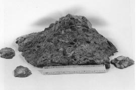
Unusual conditions may necessitate unusual methods of sampling. For example, the giant popout shown in Figure B-1A was found lying loose on a railroad tie beneath a concrete highway bridge. It was a curiosity, and we were concerned only with the reason for the popout and not with the main mass of the concrete. A method of reaching the spot on the overhead concrete was found, and the hygroscopic glass shown in Figure B-1B was recovered from the matching depression. The ordinary popouts (photographed for size contrast in Figure B-1A) were recovered loose from a highway surface. Each of these contained a fragment of porous chert at its apex. These may be considered classic popouts, pushed out of the pavement surface by the freezing and expansion of water in the porous chert. These specimens are useful reference specimens, and the chert popouts are sufficient evidence to allow the petrographer to recommend against further use of this particular aggregate in wearing courses, but the sampling procedures, although sufficient, are hardly those classically specified.
B.5.5 Aggregate Specimens
It is important that the field sampling of aggregate specimens be such that the aggregate sample is truly representative of the material proposed for use and that the ratios between the various lithologies and sizes have not been influenced by the sampling procedures (Mullen, 1978; Price, 1978).
B.6 COMPARISON OF FIELD AND LABORATORY SPECIMENS
Access to laboratory-produced specimens of HCC and the mixture proportions by which they were fabricated can prove very useful to the concrete petrographer. They provide an excellent opportunity for study of specimens of HCC produced with various experimental materials. They can also provide examples of HCC produced with a large variety of types of aggregate and numerous different admixtures so that the variations among specimens can be correlated with known differences in the design of the mixture. Various curing methods under various conditions and at various degrees of maturity can also be studied. The results of the petrographic
 |
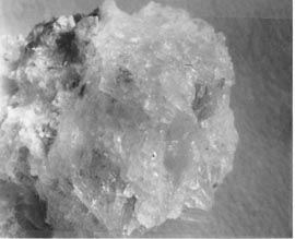 |
Figure B-1 POPOUT. A. A giant popout caused by a piece of hygroscopic glass. Accompanying it are several small popouts of a more usual size caused by porous chert particles. B. The hygroscopic glass. Natural size.
observations can be compared with the data obtained in the laboratory. The data obtained from the concrete mixing laboratory and made available to the petrographer should include the exact nature and source of the ingredients, proportions of the mixture, and results of any testing such as the following:
slump
unit weight
air content when fresh
curing method
maturity
compressive strength
permeability
results of testing for resistance to freezing and thawing results of any other testing
The concrete mixing laboratory and the concrete petrographic laboratory supplement each other. When the results of the testing done in the concrete mixing laboratory do not seem to make sense or do not explain the problem under consideration, petrographic examination may be able to provide illumination.
Construction problems usually require rapid solutions that cannot wait for results from long laboratory procedures. Waiting until a laboratory mixture is prepared, cured, and tested so that the resulting concrete can be compared with the concrete at a particular problem site is not often possible. Such experimentation must usually be performed later under more deliberate, controlled conditions. In any case, it is widely recognized that it is difficult to duplicate bad concrete in the laboratory. Features that are due to poor workmanship or incomplete mixing are especially difficult to duplicate. This may be partially due to the difference in size between a ready-mix truck and a laboratory mixer and partially due to the natural reluctance of laboratory-trained concrete technicians to violate normal procedures. Particular difficulty may be found when trying to duplicate problems that have been caused by field alteration of the mixture at the construction site. All too commonly, water was added to the mixture after the concrete began to stiffen and after the air content determinations were made. This retempering (see Appendix D) is usually not documented and must be inferred from the parameters of the concrete (Mather, 1978; Meilenz, 1978).
Investigations that include the fabrication of special concrete mixtures are really research projects but must often be undertaken before a truly informed opinion can be made of the quality, cause for particular features, or reason for failure of HCC from certain construction sites.
REFERENCES
Abdun-Nur, E. A. (1978). Techniques, procedures, and practices of sampling of concrete and concrete making materials. In Significance of tests and properties of concrete and concrete making materials (ASTM Special Technical Publication No. 169B, pp. 5-23). Philadelphia: ASTM.
Arni, H. T. (1978). Statistical considerations in sampling and testing. In Significance of tests and properties of concrete and concrete making materials (ASTM Special Technical Publication No. 169B, pp. 24-43). Philadelphia: ASTM.
ASTM. C 42: Standard test method of obtaining and testing drilled cores and sawed beams of concrete. In Annual book of ASTM standards: Volume 04.02, Concrete and aggregates. Philadelphia.
ASTM. C 457: Standard test method for microscopical determination of parameters of the air-void system in hardened concrete. In Annual book of ASTM standards: Volume 04.02, Concrete and aggregates. Philadelphia.
ASTM. C 823: Standard practice for examination and sampling of hardened concrete in constructions. In Annual book of ASTM standards: Volume 04.02, Concrete and aggregates. Philadelphia.
ASTM. C 856: Standard practice for petrographic examination of hardened concrete. In Annual book of ASTM standards: Volume 04.02, Concrete and aggregates. Philadelphia.
ASTM. D 75: Standard practice for sampling aggregates. In Annual book of ASTM standards: Volume 04.02, Concrete and aggregates. Philadelphia.
Mather, Katharine. (1978). Petrographic examination. In Significance of tests and properties of concrete and concrete making materials (ASTM Special Technical Publication No. 169B, pp. 132-145). Philadelphia: ASTM.
Meilenz, R. C. (1978). Petrographic examination. In Significance of tests and properties of concrete and concrete making materials (ASTM Special Technical Publication No. 169B, pp. 539-572). Philadelphia: ASTM.
Mullen, W. G. (1978). Weight, density, absorption and surface moisture. In Significance of tests and properties of concrete and concrete making materials (ASTM Special Technical Publication No. 169B, pp. 629-645). Philadelphia: ASTM.
Price, W. H. (1978). Grading. In Significance of tests and properties of concrete and concrete making materials (ASTM Special Technical Publication No. 169B, pp. 573-583). Philadelphia: ASTM.
C.l CAUSESAppendix C
CAUSES AND PREVENTION OF PLASTIC SHRINKAGE
CRACKING
Plastic shrinkage cracks occur when the rate of evaporation from the surface of the HCC exceeds the rate of bleeding (see ACI 224R). Bleeding is a process whereby the solids of the HCC, including the cement and other fine particles, settle and water rises to the top. (The process is thought to be a form of syneresis by some.) The bleed water makes a "sheen" on the top of the HCC. When the process proceeds as it should, water is evenly distributed throughout the thickness of the HCC placement. The water sheen on the surface prevents the top portion of the HCC from becoming drier than the bottom portion; that is, the water on the surface maintains 100% humidity throughout the concrete. The condition of 100% humidity is required so that there will be sufficient water for the remainder of the hydration to take place and so that the HCC will fill the space appropriately and not shrink.
When the proper humidity is not maintained, the top portion of the HCC becomes drier than the lower portions of the HCC and shrinkage (loss of volume) occurs within the drier portion. When HCC shrinks, it can no longer fill the space it occupies. The lower portion (where there is 100% humidity) does not shrink, and, therefore, the entire body does not change size. The drier top (the smaller portion) cracks to accommodate the shrinkage but remains attached to the larger bottom portion.
When plastic shrinkage cracking of any great extent is observed, careful inquiry into the inspector's records and the observations of others who were near the placement will almost always indicate that one or more of the following occurred:
1. The drying conditions were so severe (see Fig. C-1) that the work should have been postponed until more favorable climatic conditions existed.
2. The paving train became so strung out that there was too much time for evaporation between loss of surface water and the finishing and curing operations.
3. Curing was not begun as specified.
4. Curing was not maintained as specified:
C.2 PREVENTION
When finishing is complete and the sheen disappears by evaporation of the surface bleed water, curing procedures must begin promptly. At this point, there is no layer of water to protect the HCC from drying or maintain the 100% humidity within the HCC. If there is a wind blowing, the humidity is low, the ambient temperature is
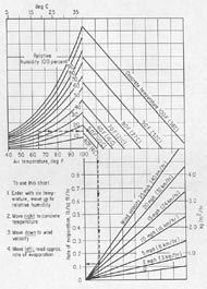
Figure C-1 EFFECT OF AMBIENT CLIMATIC CONDITIONS ON RATE OF EVAPORATION. Effect of concrete temperature, air temperature, wind velocity, and relative humidity on the rate of evaporation of surface moisture from a concrete surface. If the rate of evaporation approaches the danger point for the concrete being used, precautions against plastic shrinkage cracking are necessary (ACI Manual of Concrete Practice, updated yearly).
high, or the temperature of the HCC is high, the rate of evaporation will be especially rapid. Promptness is the essence of efficient curing. Figure C-1 shows how all of these conditions combine to contribute to the rate of evaporation.
For ordinary bridge deck concrete, the rate of evaporation should not exceed 0.1 lb/ ft2/hr (0.5 kg/m2/hr). For latex-modified concrete overlays and other cement concrete with a water-cement ratio less than 0.40, the maximum evaporation rate must not exceed 0.05 lb/ft2/hr (0.25 kg/m2/hr) (Kuhlman, 1991).
The curing procedures must be maintained properly. When climatic conditions are very unfavorable, it may be necessary to raise the humidity by misting the air over the concrete, erecting wind breaks or sunshades, or limiting the placement of HCC to cooler nighttime hours. The moisture must be maintained in the HCC through out the curing period. It will be necessary to remoisten any curing cover (such as burlap) periodically.
C.3 LEGAL INVESTIGATIONS
The client or an adversarial witness in a court proceeding may wish to inquire concerning the following:
1. Was the shrinkage cracking noticed before the finishing operations were complete
2. Did the finishing procedures tend to hide the cracking (see Fig. 4-1)?
3. Did the inspector warn the contractor against proceeding with the placement for any reason, at any time? Why?
4. What corrections in procedure did the inspector recommend?
5. What were the data concerning concrete temperature, air temperature, humidity, wind velocity, and direction? If the climatological data are not available from the inspector's records, they can usually be obtained from a nearby airport.
REFERENCES
American Concrete Institute. (Revised yearly). ACI manual of concrete practice. Vols. 1-5. Detroit.
Kuhlman, L. A. (1991, January). Cracks in LMC overlays; How do they get there; How serious are they; What to do about them. Paper presented at the Annual Meeting of the Transportation Research Board. Washington, DC.
D.1 OVERVIEW
Retempering is the process of changing the consistency of a concrete mixture by adding water and remixing. As it is common to send the concrete to the placement site with slightly less water than the maximum that may be used, it is expected that a specified amount of water can be added if necessary The contractor may add the water because the mixture arrives at the site in a condition that would make placement and finishing difficult. These difficult HCCs are often termed "harsh mixtures." They lack workability. (The only quantitative measure of workability is slump.) (See 6.1 and 8.4; Gaynor & Meininger, 1983; Pigeon, Saucier, & Plante, 1990.)
The usual cause of a harsh mixture is a sand with a high void content (see Appendix E). Sands with a high void content are usually irregular in shape with an abundance of re-entrant angles and internal fractures and voids. Iron-stained clay coatings are common. Other causes of concrete that seems too dry are improper grading (size distribution) of the aggregate and the presence of mud or mud coatings on the aggregate. Additionally, a deficiency of fine aggregate or coarse aggregate that is oversized or has a very poor particle shape can create fresh concretes with a difficult texture.
Mixtures with a low water-cement ratio (below 0.45) can be difficult to place unless an effective water reducer is used. A good air-void system or the presence of fly ash as substituting for part of the cement can help make a mixture with a low water cement ratio more workable. Apparently, the air acts as a fluid and the particles of fly ash are more equant than those of cement and act as ball bearings.
D.2 A LIKELY RETEMPERING SCENARIO
Rims of cement on the aggregate and knots of cement in the paste (see 8.7) suggest that the following typical scenario may have occurred. When the ready-mix truck arrived at the job site, it was quickly noted that the fresh HCC had a rough texture and looked as if it required more water. If the mixture was designed to have a low water-cement ratio, each of the aggregate particles in the mixture was completely coated with this very adhesive mixture. Such HCC may be very difficult to place unless a sufficient quantity of a water-reducing admixture was used. If the coarse aggregate is oversized or has a poor shape or the sand is present in an insufficient amount, is unusually angular, contains many cracks, or has many re-entrant angles, the mixture will look stiff and difficult to place (harsh mixtures). It is common under such circumstances for water to be added to the mixture to increase the slump and workability. The additional water must not increase the total water above that designed for the mixture lest the concrete become weakened because of the higher water-cement ratio.
D.3 EFFECT OF RETEMPERING
D.3.1 On HCC Paste
When water is added after hydration of the cement has begun and mixing restarted, it commonly happens (especially in mixtures with a low water-cement ratio) that the water is not distributed throughout the entire mixture but is mixed only into the larger spaces between the aggregates. The material already adhering to the aggregates remains as a rim of darker material with a low water-cement ratio around the aggregate particles and in the re-entrant angles. Patches of the original paste (unaltered by the additional water) may remain and can be found completely surrounded by the paste of higher water content. The problems of incomplete mixing are akin to the problems encountered in certain cooking situations. With gravy or white sauce, the thickening agent (such as flour) must be completely mixed with the cool water before the flour is affected by heat and begins to hydrate. If the flour and hot water mixture becomes too coherent, it may be impossible to add more water and create a smooth paste. The added water will mix with only a portion of the paste, and lumps of flour coated with stiff hydrated material will remain no matter how much mixing takes place.
Whenever water is added to the mixture without additional cement being added, the water-cement ratio is raised. The higher the water-cement ratio, the weaker the HCC. When more than the allowable amount of water for a given amount of cement is added to the mixture, the HCC will not have the designed strength. When the rims indicating incomplete mixing are present, a large portion of the cement can be concentrated in the thin bands of very rich paste around the aggregate and in the lumps of the original paste. The remainder of the paste is relatively depleted of cement and is thereby weaker than would be expected from the water-cement ratio calculated from the originally delivered mixture plus the additional water. Thus, it can be seen that areas of HCC with a high water-cement ratio can exist in close proximity to areas with a low water-cement ratio.
It must be remembered that any material is only as strong as its weakest zone. Stress in HCC in service or in a testing apparatus will cause cracking. Cracks will always follow the zones of weakness. In HCCs that have paste areas with different water-cement ratios, the cracks are going to develop in the areas of higher water-cement ratio and thus the strength will be dependent on the extent and continuity of those areas.
The skeptic will mention the fact that the bond between the aggregate and the paste in many HCCs is the weakest area and say that the dark rims of high cement content eliminate this problem. Although this is true, the fact that weak bond areas are not as continuous throughout the paste as are the light-colored areas with a high water-cement ratio (low cement content, high water content) obviates the value of rims with a high cement content as bonding agents.
D.3.2 On Air Voids
D.3.2.1 Quantity
Air-entraining agents are more active in the presence of additional water. When retempering has occurred and the mixing has not been complete, petrographic examination will show that many portions of the paste have a much higher void content than does the HCC of the rims and dark patches. Thus, the weakness of the portion with a high water-cement ratio is compounded by the portion containing more than its proportionate share of air voids. In moderate cases, the spacing factor of the air-void system may change very little because the spacing factor is most dependent on the very small voids. Pigeon et al. (1990) reported that there was little change in the spacing factor in the mixtures they studied if the retempering did not increase the slump by more than 4 in. (100 mm).
D.3.2.2 Shape
When remixing takes place after some coalescence of the HCC has occurred, the remixing may occur after the individual integrity of some of the small air voids has formed. In such cases, many of these voids will retain their surface area but lose their original spherical shape and become ovoid, or squashed, or develop an angular shape. Many angular voids may be seen in Figure 8-1.
D.3.2.3 Size
Retempering can cause an increase in the size of air voids, the number of air voids, or both. The size of the voids caused by retempering as evidenced by the microscopical examination shows that the larger voids (more than 1 mm across) nearly all occur within the portion with the higher water-cement ratio. In normal, well proportioned HCC, the percentage of voids whose diameter expressed on the surface examined exceeds 1 mm should be less than 2% of the total concrete.
REFERENCES
Gaynor, R. D., & Meininger, R. G. (1983). Evaluating concrete sands. Concrete In- ternational, 5(12): 53-60.
Pigeon, M., Saucier, F., & Plante, P (1990, May-June). Air-void stability: Part IV, Retempering. ACI Materials Journal, 87(3): 252-259.
E.1 OVERVIEW
Usually, the aggregates used in HCC are naturally occurring earth materials that have been crushed, graded, and washed as needed to meet the requirements of the concrete being produced. The amount of beneficiation required will depend on the nature of the aggregate and the requirements of the specifications. Often, transporting the aggregate is more costly than obtaining it from the quarry (presumably cleaned and sized). Therefore, aggregate sources near the concrete production plant are often preferred over sources of higher quality material located at a greater distance. The preparation of aggregate specimens for petrographic examination is described briefly in 5.5.
Not all natural rocks are suitable for use as aggregate. The material used must pass certain tests as specified in ASTM C 33 and any specification document provided by the client, customer, or purchaser. In Virginia, the document is the Road and Bridge Specifications (1991).
The petrographic description of the aggregate should be guided by ASTM C 125 (standard terminology for concrete) and ASTM C 294 (descriptive nomenclature for aggregates). The procedures given in ASTM C 295 (petrographic examination of aggregates) can be used when a supply of the aggregate is available. Detailed information may be found in Dolar-Mantuani (1983), Meilenz (1978), Mullen (1978), Ozol (1978), Price (1978), and Schmitt (1990). Basic texts on petrology, petrography, and mineralogy should be available and familiar to all persons doing this work (see the Reading List). Any person performing petrographic examinations of HCC or aggregates or who is engaged in specifying aggregate properties should carefully study the literature on earth materials and the works on concrete aggregates.
The HCC petrographer who generally works with concretes fabricated in a given area, such as a state or group of states, will find that the more familiar he or she becomes with the aggregates from that area the easier the aggregate identification will become. A collection of reference aggregates is very helpful. The aggregates should be identified as to quarry, approximate date quarried, geologic formation, and rock type. The collection should include specimens of concrete containing the aggregate as well as specimens of the unused aggregate.
The ability of aggregate to withstand the stresses induced during the mixing of HCC is very important, and, therefore, aggregates must be able to conform to the abrasion resistance specified in ASTM C 33 (specification for concrete aggregates) as tested in accordance with ASTM C 131 (resistance to degradation of small-size coarse aggregate) or ASTM C 535 (resistance to degradation of large-size coarse aggregate). Commonly, the external characteristics of the aggregate (such as distribution of the particle sizes, shape, texture, surface coatings, type of fracture, surface area, and so forth) are more important to the behavior of aggregates in HCC than is the mineral and chemical composition of the aggregate. Mullen (1978) provided an excellent explanation of these properties. A summary of some of these testing procedures may be found in the ASTM Manual of Aggregate and Concrete Testing (1990). The fine aggregate (that passing a No. 4 [4.75 mm] sieve) requires specialized testing (Gaynor & Meiinger, 1983).
E.2 COARSE AGGREGATE
Coarse aggregate (that retained on a No. 4 [4.75 mm] sieve) for use in HCC is selected mainly on the basis of durability, size, general shape, mineral composition, economy, and availability. Figures E-1 and E-2 illustrate aggregate particle shapes that are avoided when economic reasons permit.
The requirements of the proposed HCC placement must be fully considered. A placement that has many reinforcing bars close together will require a much smaller coarse aggregate than one with no reinforcement. Preplaced aggregate is often very large and always lacking in the finer size (see Lamberton [1978]). In certain cases, the specific gravity or mineral composition of the aggregate is important. A high specific gravity will make it more difficult to prevent segregation, but the use of aggregate of high specific gravity may be dictated by availability of aggregate or specific use of the concrete. Refer to any specifying document of the client to determine the fitness of a coarse aggregate to meet the requirements of the HCC (see E.6).
E.3 FINE AGGREGATE
Sand (fine aggregate) for use in concrete should be tested for shape and surface smoothness. If the particles have angular shapes with abundant re-entrant angles, the sand has a high void content and a high water demand. It takes more fluid (or cement paste) to surround an angular particle than to surround an equant particle. Among solid shapes, the ratio of surface area to volume is smallest for spheres and largest for extremely lath-shaped particles and particles with deep re-entrant angles and internal cracks and cavities. If the fluid present is insufficient to coat the surface area, the concrete mixture is harsh and difficult to place and finish. This condition is perceived, during construction, as a need for more water.
It is almost impossible to estimate the void content of a sand from a petrographic examination of a finely lapped slab because the visual contrast between the paste and the sand particles is very low unless the sand is stained or coated. The particle shape is tested by determining the void content by means of Virginia Test Method No. 5 (Virginia Department of Transportation), the test method described in Gaynor and Meininger (1983), or ASTM C 29. The test measures the unforced packability of the aggregate and thus indirectly measures the water demand of the aggregate. A concrete with a high water demand will often prompt the performance of a retempering procedure. In thin section, the outline of the sand particles can be easily distinguished from the paste by means of the birefringence of the sand particle. (Very few sand particles have birefringence as low as that of the paste.) In fluorescent microscopy, where the thin section is impregnated with a fluorescent dye, the outline of the aggregate is emphasized because the aggregate is not illuminated by fluorescence and the porous paste is. The weak zones caused by the high water demand are exceedingly porous, contain very large capillaries, and become brightly illuminated by the fluorescence of the impregnating dye (see Figs. 13-13 and 13-14). Gaynor and Meiinger (1983) also detailed a few of the other tests sand should pass.
 |
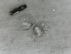 |
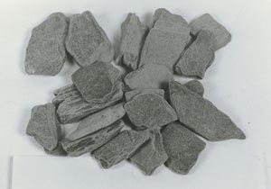
Figure E-1 SHAIJY PARTICLE SHAPE. A. Particle shape of a crushed slate aggregate. B. Pavement surface with a flaw caused freezing and thawing of water trapped under a particle of the aggregate shown in A.
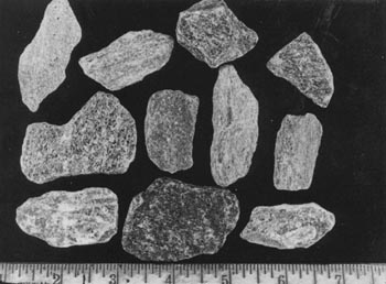
Figure E-2 AGGREGATE PARTICLES FROM FISSILE GNEISS. A particle shape such as this can cause a high water demand and popouts such as those shown in Figure E-1B
E.4 IDENTIFICATION OF ROCK TYPE
When required, the exact mineralogical identification of natural and artificial aggregates can be performed by classical petrographic methods. Monomineralic aggregates and the minerals of which the rock is composed can be properly identified. The methods used may include determining the optical properties by use of the petrographic microscope when the aggregate is examined in grain mount, thin section, or both; various methods of determining the chemicals present; determining the crystal structure by x-ray diffraction; and matching x-ray diffraction patterns for positive identification. There are many excellent books written on these methods, and courses on these methods are taught in the materials engineering and geology departments of numerous universities (see the Reading List).
The naming of rocks that are composed of mixtures of several minerals (as are most rocks) will require some knowledge of rock classification methods, i.e., how the ratios between the various minerals influence the name of the rock. The names of sedimentary rocks are usually easy to understand and use. Such terms as sandy limestone and fissile shale are self-explanatory. The major type of confusion results with a word such as marble. To an architect, an engineer, or a building contractor, the word means any decorative, polishable stone. To them, the word refers to the appearance of the rock and its engineering properties. To a geologist, the word means carbonate rock that has undergone metamorphism. Metamorphism includes recrystallization, mineral and fossil replacement, folding, crushing, and/or recementation. In general, the engineer is unconcerned with the geologic origin of a rock material. The specific geologic names of the igneous rocks can be confusing because they involve very specific grain-size classification, mineral identification, and often quantitative determination of the relative amounts of the types of feldspar and the mafic minerals present. The contractor or engineer finds such exact classification unnecessary and will often call all coarse-grained, light-to-medium colored, hard, tough rocks granites and all fine-grained, hard, dark rocks trap rocks.
When the equipment is readily available, x-ray diffraction, x-ray fluorescence, scanning electron microscopy, and transmitted electron microscopy can be used for exact mineral identification. Such identification is necessary only when the distinction between similar rocks might elucidate the reasons for differences in durability or other behavior when the aggregate in question is used in HCC.
Most often, the exact identification is not necessary. Usually, the most detailed examinations are required when alkali-aggregate reactions are suspected or carbonate rocks are suspected of causing D-cracking (Schwartz, 1987). For more data on alkali-reactive aggregates, refer to Chapter 10 and the associated figures and references, the related ASTM standards (Reading List), and the section on thin-section preparation (5.2).
E.5 AGGREGATE CONCERNS IN D-CRACKING
D-cracking that is due to destruction of the aggregate by freezing and thawing has been well documented in the literature, and much information concerning it can be easily found (Schwartz, 1987). Both the alkali-carbonate reaction and D-cracking involve dolomitic limestones whose composition includes a large portion of insoluble material. Dolomites involved in D-cracking are thought to require a certain fine pore structure and/or contain a minor amount of iron, strontium, or both in their crystal structure (Dubberke & Marks, 1987; Schwartz, 1987). A specific pore structure and iron or strontium do not seem to be necessary conditions for the alkali carbonate reaction. The crack patterns produced by these two reactions are very different. D-cracking deterioration is first evident at the edges and near the joints of a pavement. The cracking is parallel to the joint or edge (see Fig. E-3 and compare with Figs. 10-15 through 10-17). The alkali-carbonate reaction is an expansive chemical reaction with the alkalies, whereas D-cracking is caused by freezing and thawing of moisture in the particles of certain susceptible dolomites and does not involve alkalies.
I have had no experience with D-cracking because it has not been found in Virginia. Schwartz (1987) stated:
In Iowa, Dubberke and Marks (1987) found that D-cracking is not necessarily related to the pore structure of the aggregate and came to the conclusions that the in
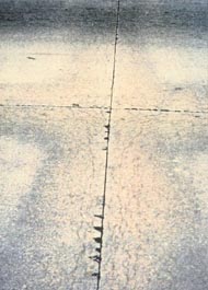
Figure E-3 D-CIRACKTNG. D-cracking of a pavement due to destruction of the aggregate by freezing and thawing. The cracking parallel to the joint and wrapping around at the juncture of joints is indicative of D-cracking.
cidence of D-cracking is higher with ferroan-dolomite aggregates than with other compositions and D-cracking may be due to or hastened by a chemical reaction with deicing salts.
E.6 SPECIAL PURPOSE AGGREGATES
E.6.1 Skid Resistance
Skid resistance is usually desired for any aggregates used in a surface of HCC that supports traffic. Skid resistance requires that the surface of an HCC pavement be fabricated with hard, nonpolishing aggregates. This generally means that nonsiliceous carbonate rocks cannot be used. In areas where carbonate aggregate is much less expensive than harder aggregate from more distant sources, two-course construction may be the most economic alternative. Not all types of siliceous aggregate provide the same wearing-surface microtexture as others. Despite their hardness, some quartz and feldspar pebbles and quartzitic and granitic rocks may tend to wear with a rounded surface and to polish (see Fig. E-4). Others with certain zones of weakness such as certain granites and graywackes wear and then break with a microtexture that creates a very skid-resistant wearing surface (see Fig. E-5) (Webb, 1970).
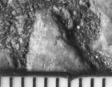
Figure E-4 TRAFFIC-WORN ROUNDED SURFACE OF FELDSPAR AGGREGATE PARTICLE. This will not provide good skid resistance. The scale is in millimeters.
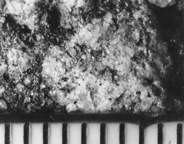
Figure E-5 TRAFFIC-WORN SURFACE OF GRANITE AGGREGATE PARTICLE. This has zones of weakness to provide an irregular skid-resistant surface. The scale is in millimeters.
E.6.2 Lightweight Aggregates
Lightweight aggregates may be specified whenever the weight of conventional aggregates might be a problem. They are frequently used for long span bridges to alleviate the dead load on the support structures. They may be used when bridge decks require widening and it is considered more economical to widen with the more expensive expanded aggregates than to increase the strength of the support structure.
Manufactured lightweight aggregates are usually shale or slate that has been expanded by treatment at very high heat. The exterior of the particles becomes fluid, and the gases and vapors inside expand to create a very porous substance with a fused exterior shell. Figure E-6 shows this sort of aggregate exposed on a lapped slice of HCC.
These expanded aggregates vary considerably with the source material used and the nature of the heat treatment (temperature, time, oxidation conditions, etc.). Much depends on the depth and continuity of the fused surface of the aggregate particles. If this surface is continuous, the aggregate will have a low permeability despite its high porosity.
It is suspected that the chemical composition of the fused layer may have an important effect on the ability of these aggregates to bond with cement paste. Certain expanded aggregate materials produce concretes in which the bond between the aggregate and the paste is extremely good. In other cases, the bond is no better than would be expected of a quartz-pebble aggregate. In the examples of a good bond,
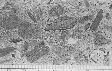
Figure E-6 LAPPED SLICE OF HCC FABRICATED WITH EXPANDED LIGHTWEIGHT AGGREGATE. The scale is in millimeters.
the aggregate surface does not seem to have an attraction for water, as does quartz and many other highly siliceous materials. These layers of water on the surface of aggregate particles create space along the bond line in the finished concrete that, whether or not it fills with calcium hydroxide, is a zone of weakness in the concrete and a possible channel for water, salt solutions, and other liquid materials. It has been shown that this attraction for water that lessens the paste-aggregate bond is most often present in materials that are acidic by nature whereas the materials that may be considered mafic or alkaline, such as the carbonates and iron-rich minerals, generally have a much tighter bond (Walker, 1972b). It has not yet been shown that the chemical composition of the fused layer in expanded aggregate has a direct effect on the properties of the bond. I suspect that such research would be likely to yield interesting and useful results.
Certain rocks can be used as lightweight aggregates without heat treatment. These may include volcanic ashes, tuffs, and pumices.
E.6.3 Radiation Shielding
Concrete for radiation shielding is designed using heavy-weight or special composition aggregates so that the maximum amount of radiation may be contained. These requirements are dealt with in ASTM C 637 and ASTM C 638. Many of the aggregate minerals used in radiation shielding are opaque, and identification cannot be determined with the petrographic microscope. If the exact mineral identification is required, x-ray diffraction and some form of chemical testing or examination with a metallographic microscope will have to be performed.
REFERENCES
ACI. 211.1: Standard practice for selecting proportions for normal, heavy weight, and mass concrete. In ACI manual of concrete practice: Part 1, Materials and general properties of concretes. Detroit.
ACI. 211.2: Standard practice for structural lightweight concrete. In ACI manual of concrete practice: Part 1, Materials and general properties of concretes. Detroit.
ASTM. C 29: Standard test method for unit weight and voids in aggregate. In Annual book of ASTM standards: Volume 04.02, Concrete and aggregates. Philadelphia.
ASTM. C 33: Standard specification for concrete aggregate. In Annual book of ASTM standards: Volume 04.02, Concrete and aggregates. Philadelphia.
ASTM. C 125: Standard terminology relating to concrete and concrete aggregates. In Annual book of ASTM standards: Volume 04.02, Concrete and aggregates. Philadelphia.
ASTM. C 131: Standard test method for resistance to degradation of small-size coarse aggregate by abrasion and impact in the Los Angeles machine. In Annual book of ASTM standards: Volume 04.02, Concrete and aggregates. Philadel phia.
ASTM. C 294: Standard descriptive nomenclature of constituents of natural mineral aggregates. In Annual book of ASTM standards: Volume 04.02, Concrete and aggregates. Philadelphia.
ASTM. C 295: Standard practice for petrographic examination of aggregates for concrete. In Annual book of ASTM standards: Volume 04.02, Concrete and aggregates. Philadelphia.
ASTM. C 330: Standard specification for lightweight aggregates for structural concrete. In Annual book of ASTM standards: Volume 04.02, Concrete and aggregates. Philadelphia.
ASTM. C 535: Standard test method for resistance to degradation of large-size coarse aggregate by abrasion and impact in the Los Angeles machine. In Annual book of ASTM standards: Volume 04.02, Concrete and aggregates. Philadelphia
ASTM. C 637: Standard specification for aggregates for radiation shielding. In Annual book of ASTM standards: Volume 04.02, Concrete and aggregates. Philadelphia.
ASTM. C 638: Descriptive nomenclature of constituents of aggregates for radiation-shielding concrete. In Annual book of ASTM standards: Volume 04.02, Concrete and aggregates. Philadelphia.
ASTM. Manual of aggregate and concrete testing. In Annual book of ASTM standards: Volume 04.02, Concrete and aggregates (related material). Philadelphia.
Dolar-Mantuani, L. (1983). Handbook of concrete aggregates. Park Ridge, NJ: Noyes Publications.
Dubberke, Wendell, & Marks, Vernon J. (1987). The relationship of ferroan dolomite to rapid concrete deterioration (TRR No. 1110, pp. 1-10). Washington, DC: Transportation Research Board.
Gaynor, R. D., & Meininger, R. C. (1983). Evaluating concrete sands. Concrete International, 5(12): 53-60.
Lamberton, B. A. (1978). Preplaced aggregate concrete. In Significance of tests and properties of concrete and concrete making materials (ASTM Special Technical Publication No. 169B, pp. 528-535). Philadelphia.
Meilenz, R. C. (1978). Preplaced aggregate concrete. In Significance of tests and properties of concrete and concrete making materials (ASTM Special Technical Publication No. 169B, pp. 539-572). Philadelphia: ASTM.
Mullen, W. G. (1978). Weight, density, absorption and surface moisture. In Significance of tests and properties of concrete and concrete making materials (ASTM Special Technical Publication No. 169B, pp. 629-645). Philadelphia: ASTM.
Ozol, M. A. (1978). Shape, surface texture, surface area, and coatings. In Significance of tests and properties of concrete and concrete making materials (ASTM Special Technical Publication No. 169B, pp. 584-628). Philadelphia: ASTM.
Price, W. H. (1978). Grading. In Significance of tests and properties of concrete and concrete making materials (ASTM Special Technical Publication No. 169B, pp. 573-583). Philadelphia: ASTM.
Schmitt, James W. (1990). Effects of mica, aggregate coatings, and water-soluble impurities on concrete. Concrete International, 12(12): 54-57.
Schwartz, Donald R. (1987). D-Cracking of concrete pavements (NCHRP Synthesis No. 134). Washington, DC: Transportation Research Board.
Virginia Department of Transportation. (1991). Road and bridge specifications. Richmond. (Revisions scheduled every four years).
Virginia Department of Transportation, Materials Division. Virginia Test Methods Manual (various). Richmond. (Revisions individually, as required).
Walker, Hollis N. (1972). The stripping of penetration 85-100 asphalt from silicate aggregate rocks: A laboratory study (VHRC Report No. 71-R29). Charlottesville: Virginia Transportation Research Council.
Webb, John W. (1970). The wearing characteristics of mineral aggregates in highway pavements (VHRC Report No. 70-R7). Charlottesville: Virginia Transportation Research Council.
F.1 METHODS OF PREVENTION
Table F-1 lists the methods of preventing the deterioration caused by the alkali-silica reaction.
Table F-1
METHODS OF PREVENTING DESTRUCTIVE ALKALI-SILICA REACTION
1. Specify a low-alkali cement (not often practical).
2. Specify nonreactive aggregates (if possible).
3. Use an effective pozzolanic additive or blended cement such as:
Note: At the present time, there is no reason to believe that pozzolans will ameliorate destructive alkali-carbonate reactions.
F.2 USE OF POZZOLANIC MATERIAL
The mechanism(s) by which a pozzolanic additive or a pozzolanic cement reduces the expansion of the alkali-silica reaction is not well understood. There are three mechanisms that may be active:
1. The pozzolanic material may react with the hydroxide ions associated with the sodium and potassium ions in solution in the paste during the early stages of hydration and sequester the deleterious ions in gels that, because of their location or composition, cannot cause deleterious expansion. If all the alkalies are contained in such gels, no expansive gel will form at a later stage.
2. All pozzolanic materials combine with the lime in cement paste to produce cementitious calcium silicate hydrates and thus reduce the quantity of the lime in the HCC. This general reduction in the amount of lime may change the ability of the gel pockets to imbibe water.
3. The pozzolans promote the formation of a concrete that is much less permeable than concretes fabricated without them. Thus, a concrete is produced through which solutions cannot move as readily. Concrete fabricated with GGBFS as 60% of its cementitious material has been found to be 1/10 to 1/100 as permeable as comparable concrete without GGBFS at equal strength (B. Mather, personal communication, October 1991).
All three of these mechanisms may be active concurrently. In any case, it is well established that sufficient pozzolanic material (in the case of silica fume, sometimes only 4% of the weight of the cement) will dramatically reduce the expansion and prevent alkali-silica deterioration. The appropriate amount can be determined in accordance with ASTM C 441.
In general, the replacement of a portion of the cement by a reasonable amount of an efficient pozzolan has few contraindications. When combined with the lime of cement, a pozzolan forms a cementitious material. It was extensively used by the Romans. Good quality GGBFS has been successfully used in amounts up to 65% of the cement. Fly ash may be used in up to 20% of the cement. Silica fume is costly and in Virginia is not usually used in amounts larger than 8%. Large amounts of pozzolan (except silica fume) can delay final set and, thus, can necessitate the delay of form removal in cold weather (see Chapter 11). The final compressive strength of the HCC can, however, be as high or higher than it would have been if a portion of the cement had not been replaced. If quality control is not good, certain pozzolans can create other problems.
If fly ash has a large carbon content, it will adsorb organic chemicals, such as air-entraining agents. The carbon in fly ash acts as does activated charcoal. Its large surface area is capable of absorbing large amounts of orgamc chemicals. This is the reason activated charcoal is used as a filter in aquariums. When thus adsorbed, the air-entraining agent does not work efficiently. The resulting HCC may not contain an air-void system with the parameters necessary for a concrete protected from freezing and thawing distress. The carbon content can be measured by the amount of loss of mass on ignition (refer to ASTM C 311). As far as is known, neither GGBFS nor silica fume causes such problems. When used as a replacement for the cement, GGBFS is economically attractive and produces a concrete resistant to many types of chemical deterioration because it not only is excellent for preventing alkali-silica expansion but also produces a concrete of low permeability and thus inhibits the circulation of solutions.
See the Reading List for a list of applicable ASTM standards. The ASTM standard methods should be used with care, and all applicable cautions taken. They should be conducted by persons who are qualified by education or experience to conduct such tests, use such standards, and take all precautions necessary for the safety of personnel and applicable equipment.
REFERENCES
ASTM. C 311: Standard test methods for sampling and testing fly ash or natural pozzolans for use as a mineral admixture in portland-cement concrete. In Annual book of ASTM standards: Volume 04.02 Concrete and aggregates. Philadelphia.
ASTM. C 441: Standard test method for effectiveness of mineral admixtures or ground blast-furnace slag in preventing excessive expansion due to the alkali-silica reaction. In Annual book of ASTM standards: Volume 04.02, Concrete and aggregates. Philadelphia.
G.1 OVERVIEW
It is obvious that there is much work still to be done in the field of petrographic concrete research and investigation. The concrete petrographer must be able to decipher the construction problems as they occur and be ready to advise engineers as to how to avoid the problems in the future. Research is required to answer the questions raised in many places throughout this manual (and others I have not mentioned) and investigate new materials and methods as they become available. New quarrying methods, new methods of construction, uses of waste material as aggregate, and new methods of obtaining laboratory data will, of course, continue to make the field a continually growing one that should always be interesting (provided funds can be found to further the necessary experimentation and investigation).
G.2 CONSTRUCTION METHODS AND MATERIALS
As with so many sciences, there are many changes and advances being made in the study and analysis of HCC by means of all of the petrographic methods. New materials are being used to fabricate and maintain HCC pavements and structures. Each of these new materials brings a new look to the microstructure of HCC, and the petrographer must continually devise new methods to keep pace (R. D. Walker, 1978).
G.2.1 Aggregate Shortages
As our civilization changes and as governmental regulations change, certain shortages in materials develop. Because a large share of the cost of aggregate is the transportation from pit or quarry to site of use, shortages in the supplies of low-cost aggregate can be due to urban expansion over older, high-quality source sites. Certain innovative companies are using expensive complex beneficiation technology to mine sand and gravel deposits with a short haul distance and find that they can compete economically with companies that have a longer haul but material that requires little beneficiation. Petrographers need to assess such cleaned-up material and the reactions of the aggregates in HCC.
G.2.2 Cement Alkalies
Due to EPA air quality requirements, and the economics and environmental value of preheaters, portland cement with a low alkali content is becoming scarce. In some cases, the cement from a single plant may vary in alkali content from season to season. Cement technologists need to assess this situation and make provisions for overcoming the problems the higher-alkali cements will create when used with the alkali-reactive aggregates.
G.2.3 Concrete
Concrete that is returned to the plant in a ready-mix truck is presently discarded, and the truck washed out to prevent the mixture setting up in the truck. (All trucks must be washed out daily.) This means that not only does the waste concrete have to be disposed of, but the wash water must also go into a settling pond before it is returned to the environment.
It has been found that this concrete can be kept in stasis over a night or a weekend if a retarder is added to the returned excess concrete. When downtime has elapsed, an accelerator can be added to neutralize the retarder and the concrete can again be ready for use.
However, it is easy to make a mistake on the dosage of these chemicals. It will require the efforts of many types of concrete technologists to discover the proper methods of conserving concrete by the use of them. As it becomes common to conserve concrete and protect the environment by such methods, the dosage errors possible will become more common and concrete petrographers will have to be on the lookout for the results of such errors.
The concrete petrographer should be continuously on the alert for the sort of problems that can be brought about by the use of new materials and techniques and should be ready to devise methods of detecting them, quantifying them, and reporting them to engineers.
G.3 CONCRETE LABORATORY EQUIPMENT
New concrete laboratory equipment becomes available and more useful as inventive persons become interested in concrete technology. New methods of using existing equipment add to our ability to discover more information concerning the different types of HCC. New advances in instrumental analysis occur all the time. The petrographer should make himself or herself aware of any new equipment and methods that could be used to advantage in petrographic examinations of HCC. If funds are available, every concrete petrographic laboratory should be equipped with the modern equipment that is presently known to be useful in the study of HCC. Such equipment includes image analysis equipment, a scanning electron microscope, and x-ray diffraction and x-ray fluorescence equipment. If these advanced types of equipment are used in the study of HCC, some of the basic questions that have remained unanswered concerning these materials might be answered.
G.3.1 Equipment for Air-Void Analysis
The equipment for the determination of the parameters of the air-void system has become varied and in some cases quite sophisticated since the early days of these determinations. At one time, there were laboratories that used two persons to make an air-void determination by the point-count method. One person was the microscopist, who verbally reported observations to the other person, who manually recorded the data with paper and pencil. Today, with the use of image analysis, once the specimen is properly prepared and the equipment properly adjusted, the analysis can proceed without the presence of any human being. This is much faster than any of the older methods and eliminates the problems of training technicians in these microscopical techniques and the problems of operator fatigue. There are, however, many concrete laboratories wherein it is preferred that the analysis be performed by a human microscopist and the specimen be uncolored by dyes or fillers. It is felt that only a human microscopist can make the subtle judgments that are often necessary. Also, there are many concrete laboratories that have not been able to budget for image analysis equipment. It can probably be assumed that some version of the microscopical methods, in which the human eye is the detector, will exist for a long time to come.
Image analysis or other methods yet to be invented may be able to determine air void parameters not considered by ASTM C 457. Such additional parameters may lead to new theories concerning the air-void system and methods of controlling it. There has been concern for a few strange occurrences of concrete that by all the known parameters of the air-void system should be able to withstand the rigors of the weather and deicing but that have failed under field conditions. This problem was addressed by Buckingham and Spaw (1988). They are working on methods of using image analysis and a large number of the specimens (to make up for the heterogeneity of concrete) to determine the distribution of spacing factors in a concrete. This is in contrast to the classical method of merely considering the average spacing factor. It is thought that the concretes that fail without discernible reason may have an uneven distribution of air voids (and thereby an uneven distribution of spacing factors), and thus there may be areas within these concretes that are unprotected by the air-void system.
There are other possible explanations for failures that cannot be explained by deficiencies of the air-void system detected by conventional methods: (1) insufficient sampling, (2) improper sampling, and (3) improper performance of the determination of the air-void parameters.
G.3.2 Equipment for Detecting Ionic Permeability
The rapid chloride ion permeability test devised by D. Whiting (1981) is a good method for obtaining the relative permeability of HCC to chloride ions (and by analogy permeability to many other ions). Appendix I in his report gives detailed instructions on the method of test. Trained technicians can easily perform this test without the close supervision of a petrographer or chemist. A comparison of the results of this or similar tests could be correlated with the features visible to a petrographer (with the stereomicroscope, the P/EF microscope, or both), and new insights could be gained as to the meaning of the visible features of HCC.
G.4 FREEZING AND THAWING OF CONCRETE
The specification for the percentage of air to be entrained in concrete resistant to freezing and thawing has been devised to protect saturated concrete from the freezing of the water contained therein. We have little or no knowledge concerning what the saturated state is. Although the RH within the concrete can be measured, we have no method for measuring the degree of saturation. We do not know if the entrained air voids become partially water filled or if they are completely empty when the concrete is susceptible to freezing and thawing distress. Although we know that water in a very small space cannot freeze, we do not know what portion of the water in a concrete system becomes frozen or at what temperature the water in the various sizes of capillaries freezes.
Deicers increase the severity of freezing and thawing distress. The reason for this has never been fully investigated. Does the salt increase the number of cycles of freezing and thawing or does the salt scattered on the surface, by dissolving in water and taking up heat (as with freezing ice cream), actually lower the temperature in the top layer of the concrete and thus increase the depth of freezing?
We theorize that the air-void system provides relief from the pressures caused by freezing. I am not sure that we know the carrier of those pressures. Is water or air forced ahead of the freezing front? Is it forced into the air voids? Would nonpermeable but collapsible plastic-coated spheres provide any protection?
Is it possible to have a concrete so completely saturated and subjected to a freezing temperature (whatever that is) for such a long time and so repeatedly that the air-void system (regardless of how good) can fail to protect the concrete?
G.5 ALKALI-AGGREGATE REACTIONS
We know that the alkali-aggregate reactions require reactive aggregate, alkalies in the cement or in contaminants, and water. We are fairly certain that the alkali- carbonate reactions are active at a lower alkali content than are the alkali-silicate reactions with the more reactive silica-bearing materials. We do not have a good idea of the exact minerals or the state of crystallization of the minerals involved in the slower alkali-silica reactions or of the alkali limits required to prevent these reactions. The present thinking is that the addition of sufficient good-quality pozzolanic material will prevent these reactions indefinitely. So far, this theory has not been around long enough to be substantiated. It may be that we should not be thinking about preventing these reactions completely but rather should be concerned with preventing them over certain periods of time.
All of these reactions have had numerous theories about their exact mechanisms reported in the literature. Many of these theories seem to be contradictory or conflicting. Some questions remain unanswered. Is there an osmotic cell mechanism in operation when silica gel imbibes water and expands and causes distress? What is the nature of the expansive material in an alkali-carbonate reaction?
It has been reported that alkali-silica distress is more severe where the structure has received deicing salts. Is this solely due to the sodium and potassium salts present in a particular kind of deicing chemical used or does pure NaCl also increase the distress? Is there any similar effect on the alkali-carbonate reaction?
G.6 CONTENTS OF CEMENT IN CONCRETE
Because the cement is the most expensive ingredient in concrete, the purchasers of this material are concerned about whether or not the concrete contains the specified amount of cement. In our experience, in Virginia, under government contract, it is only very rarely that a concrete supplier either by accident or design fails to supply concrete with the sufficient cement content to the job site. The problems usually arise when water is added at the construction site to facilitate placement and finishing. Under these circumstances, the concrete placed may have a high water-cement ratio, may fail the strength requirement, and may not be as durable as would be expected from the design of the mixture. There have been many tests devised to determine either the amount of cement or the water-cement ratio of fresh concrete. However, as in so many other cases, no test is worth the trouble it takes if it is not performed on the material representative of the final product purchased. It does not appear likely that any of these tests on fresh concrete would be very helpful. Research should be devised to enable the specifications to inform the contractor what to do when any problem arises that has in the past led to the addition of water and retempering. In many cases, the prohibition against using aggregates with a high water demand unless sufficient water-reducing admixture additive of an approved type be employed should be enforced. The petrographer can be instrumental in the devising and enforcement of proper specifications.
G.7 DETERMINATION OF AGGREGATE SIZE
At the present time, VTRC is not able to make a determination by optical means of the amount of a specific size or the ratio between sizes of aggregate in hardened HCC unless the size range of particle to be determined differs in lithology or color from other particles of aggregate occurring in the HCC. (If all the paste was dissolved away, a sieve analysis would be possible.) An optical method of determining particle sizing could be the comparison of results of determining chord lengths across the particles (by linear traverse or image analysis), with similar determinations made on hardened laboratory-fabricated HCC mixtures with known particle sizing. A large number of standard specimens would be required to determine the sizes in the mixture within meaningful limits. To date, it has not been felt that such work would be worth the time and expense, but if the problem occurred frequently with specific aggregate sources, it might be used in the future. Kite and Walker (1978) investigated particle angularity by chord length measurements, but, as far as is known, no effort has been made to determine sizes of irregularly shaped particles by such a method.
G.8 USE OF WASTE MATERIALS IN CONCRETE
Some of the waste materials of mining and manufacturing processes are rarely used for any purpose and merely collect or are stored on land that is thus wasted and unsightly. Fly ash, silica fume, and GGBFS were once merely waste products and are now used (after beneficiation) as valuable particulate ingredients in HCC. Certain mining operations set aside overburdens that may be composed of rocks that might be used when sized and sintered for lightweight aggregate. The utility industry has excess bottom slag that may be used as aggregate under controlled conditions. There has been much hypothesizing and some experimentation concerning the use of various other waste materials in HCC. It would solve many problems if the human race could use its nonrecyclable and excess crushed glass and plastic, garbage, waste paper, mildly radioactive waste, slag (all types), cinders, and other waste as aggregate in building materials. (We are already aware of some of the problems that might occur if the waste products used as aggregate are not stable in the concrete paste environment.) As yet, it seems that most technical people are skeptical of the stability, durability, and safety of HCC constructed with these kinds of aggregate. It is hoped that the future will provide better repositories for our waste than the ubiquitous landfill.
REFERENCES
ASTM. C 457: Standard test methods for microscopical determination of parameters of the air-void system in hardened concrete. In Annual book of ASTM standards: Volume 04.02, Concrete and aggregates. Philadelphia.
Buckingham, William, & Spaw, Joan M. (1988). Direct measure of spacing factor in air entrained concrete. In Proceedings of the Tenth International Conference on Cement Microscopy (pp. 82-92). Duncanville, TX: International Cements Microscopy Association.
Kite, L., & Walker, H. N. (1978). Determination of shape of fine aggregate by microscopic examination of hardened concrete. Unpublished manuscript. Charlottesville: Virginia Transportation Research Council.
Walker, R. D. (1978). Needed research. In Significance of tests and properties of concrete and concrete making materials (ASTM Special Technical Publication No. 169B, pp. 49-56). Philadelphia: ASTM.
Whiting, D. (1981). Rapid determination of the chloride permeability of concrete (FHWA Report No. RC-81/119). Skokie, IL: Construction Technology Laboratories.

