U.S. Department of Transportation
Federal Highway Administration
1200 New Jersey Avenue, SE
Washington, DC 20590
202-366-4000
Federal Highway Administration Research and Technology
Coordinating, Developing, and Delivering Highway Transportation Innovations
| REPORT |
| This report is an archived publication and may contain dated technical, contact, and link information |
|
| Publication Number: FHWA-HRT-15-080 Date: February 2016 |
Publication Number: FHWA-HRT-15-080 Date: February 2016 |
This report focuses on the service limit states (SLSs) of deformations and stresses of engineered fills used as bridge supports for abutments and piers. The engineered fills focus on compacted granular engineered fills of mineral origin and reinforced soil systems. The SLSs ensure the durability and serviceability of a bridge and its components under typical everyday loads, traditionally termed “service loads.”(1) In this report, “service limit” refers to the vertical and lateral deformations of bridge supports.
The use of engineered fills with and without layered reinforced soil systems is an economical solution to reduce deformations and improve bearing resistance of shallow foundations for bridge supports. Notable studies of spread footings on engineered fills published by the Federal Highway Administration (FHWA) concluded that this technique was a suitable alternative to deep foundations.(2,3) Engineered fills can be used to support bridge abutments and piers with various configurations. In bridge abutments, the engineered fills can be compacted granular fills or compacted granular fills with metallic or geosynthetic reinforcement, while in bridge piers, the engineered fills can be compacted granular fills or compacted granular fills with geosynthetic reinforcement. Bridge supports using reinforced engineered fills contribute to better compatibility of deformation between the components of bridge systems, thus minimizing the effects of differential settlements and the occurrence of undesirable “bumps” between the bridge deck and the approach embankment transitions.(4) Recent FHWA national surveys revealed that State transportation departments have safely and economically constructed highway bridges supported on spread footings bearing on competent and improved natural soils as well as engineered granular and mechanically stabilized earth (MSE) fills.(5)
Despite these advantages, many transportation agencies do not consider shallow foundation alternatives, even when appropriate, for a variety of reasons, including concerns related to meeting serviceability requirements (e.g., vertical and lateral deformations). Due to the large size of spread footings for highway bridges, soil bearing failure is not likely.(6) Therefore, the performance of spread footings in highway bridge design is evaluated primarily on the basis of vertical displacement (i.e., settlement and how differential settlements affect angular distortion).(7) SLS for shallow foundations often controls the design of bridge foundations; however, little guidance on SLS has been provided for engineered fills.(8) According to the American Association of State Highway and Transportation Officials (AASHTO) Manual for Bridge Evaluation, SLS relates to stress, deformation, and cracking.(9) The Strategic Highway Research Program 2 (SHRP2) report, Bridges for Service Life Beyond 100 Years: Service Limit State Design presents the existing limit states and tolerances of bridge components set forth by various agencies in the United States and internationally.(10)
FHWA defines engineered granular fill as high-quality granular soil selected and constructed to meet certain material and construction specifications (also called “compacted structural fill” and “compacted granular soil”).(5) Engineered fill may be reinforced with geosynthetics or metal strips. The high quality refers to gradation, soundness, compaction level, durability, and compatibility. Such specifications are further described in table 1 and table 2.
A number of State transportation departments, including the Washington State Department of Transportation (WSDOT), the New Mexico Department of Transportation, and the Minnesota Department of Transportation, have successfully utilized compacted engineered granular fills.(5) For example, based on a survey of 148 bridges in Washington, FHWA concluded that spread footings on engineered fill can provide a satisfactory alternative to deep foundations, especially if high-quality fill materials are constructed over competent foundation soil.(2) National Cooperative Highway Research Program Report No. 651 reported higher resistance factors for the compacted granular fill than natural granular soil because of better control for compacted fill.(11) Nevertheless, concerns exist regarding the use of spread footing bearing on engineered granular and MSE fills. A number of State transportation departments have allowed and constructed spread footings on natural soils but not on engineered granular and MSE fills due to the concerns related to the quality and uniformity of compacted fill materials as well as costly design and construction of bridge footings on MSE walls.(5) Table 1 lists the FHWA material and construction requirements for engineered granular fills.(12)
| Soil Properties | Requirements | |
|---|---|---|
| U.S. Sieve Size | Percentage Passing (percent) | |
| Gradation (AASHTO T27)(13) | 4 inches | 100 |
| #40 (0.0165 inch) | 0–70 | |
| #200 (0.0029 inch) | 0–15 | |
| 1 inch = 25.4 mm | ||
Additional general considerations in selecting structural backfills are as follows:(6)
Table 2 provides general considerations in selecting structural backfills, as highlighted in FHWA’s Soils and Foundations Reference Manual: Volume I.(6)
| Consideration | Comments |
|---|---|
| Lift thickness | Limit to 6 to 8 inches so compaction is possible with small equipment. |
| Topsize (largest particle size) | Limit to less than three-fourths of lift thickness. |
| Gradation/percent fines |
Use well-graded soil for ease of compaction. Typical gradation is as follows:
|
| PI | PI should not exceed 10 to control long-term deformation. |
| Durability | This consideration attempts to address breakdown of particles and resultant settlement. The material should be substantially free of shale or other soft, poor-durability particles. Where the agency elects to test for this requirement, a material with a magnesium sulfate soundness loss exceeding 30 should be rejected. |
| AASHTO T99 density control(16) | Small equipment cannot achieve AASHTO T180 densities. Minimum of 100 percent of standard Proctor maximum density is required.(17) |
| Compatibility | Particles should not move into voids of adjacent fill or drain material. |
| 1 inch = 25.4 mm | |
The FHWA report, Soils and Foundations Reference Manual: Volume II, recommends that compacted structural fills used for supporting spread footings should be a select and specified material that includes sand- and gravel-sized particles.(18) Furthermore, the fill should be compacted to a minimum relative compaction (RC) of 95 percent based on the modified Proctor compaction energy, and structural fill should extend for the entire embankment below the footing.
In the United States, the concept and principles of MSE technology were introduced in 1969.(19) There are two basic types of soil reinforcements in MSE structures: inextensible (metallic) and extensible (polymeric). Metallic reinforcement has been primarily used as the reinforcement of soils. The first reported MSE abutment in the United States was constructed in 1974 in Lovelock, NV, to support a precast bridge span of 70 ft (21 m).(20) MSE structures built with inextensible reinforcement, such as discrete metallic strips or welded wire mats, have a unique combination of precast panels, reinforcement, and connection details.(21) For bridge supports using extensible geosynthetics, Adams is among the first to report on the performance of a pre-strained geosynthetic reinforced soil (GRS) bridge pier, which demonstrated the feasibility of such a technique in bridge supports. (22) Since then, many full-scale studies on GRS as bridge supports and many bridge abutments built using such technologies continued to recognize its advantage over conventional bridge supports. (See references 5 and 23–29.) Moreover, engineered fills have been used for bearing of bridge abutments in other countries and have also proven to be effective.(30,31) These previous studies have shown that engineered fills offer advantages of improved performance and savings in labor costs, equipment, and time. Cost savings could total up to 65 percent compared to conventional deep foundations for bridge systems.(18)
For GRS abutments, backfill selection is important because it is a major structural component for the abutment. FHWA’s Geosynthetic Reinforced Soil Integrated Bridge System Interim Implementation Guide provides recommendations for the gradations for well-graded and open-graded backfills used for GRS abutments.(32) “Open-graded material” refers to a gradation where skips between the sieve gradations have been deliberately achieved so that the voids are not filled with intermediate-size particles. The main criteria are: (1) there is a minimum friction angle (Φ) of 38 degrees, (2) the maximum grain size is between 0.5 and 2 inches (13 and 51 mm), (3) PI should be less than or equal to 6, (4) the mass percentage of soils finer than #200 sieve should be less than 12 percent, and (5) the backfill shall be substantially free of shale or other poor durability particles, and the material shall have a magnesium sulfate loss of less than 30 percent after four cycles (or a sodium value less than 15 percent after five cycles).
In addition to the gradation requirement, backfill selection depends on the following factors:(32)
FHWA indicated that for GRS abutments, reinforced soil foundation (RSF), and approach-way backfills for GRS integrated bridge systems (GRS-IBSs), the backfill of well-graded aggregates must be properly compacted to a minimum of 95 percent of maximum dry density according to AASHTO T99.(32,16)
As of 2012, all GRS-IBS projects had selected open-graded gravel due to its relative ease of construction and drainage characteristics. The various counties and agencies that are building GRS-IBS have selected locally available structural backfills for their projects.(21) Adams et al. provided the fill gradations of five GRS-IBS projects; the majority of the grains were in the range of 0.375 to 1 inch (9.5 to 25.4 mm), but their size distributions varied.(21) It is noted that how the different grain sizes affect the load-deformation behavior remains to be studied.
Using different types of engineered fills for bridge support has its benefits and limitations. One benefit is that contractors and bridge owners have wider choice and availability of backfill materials; this will result in savings in cost and labor.
The limitations include the following:
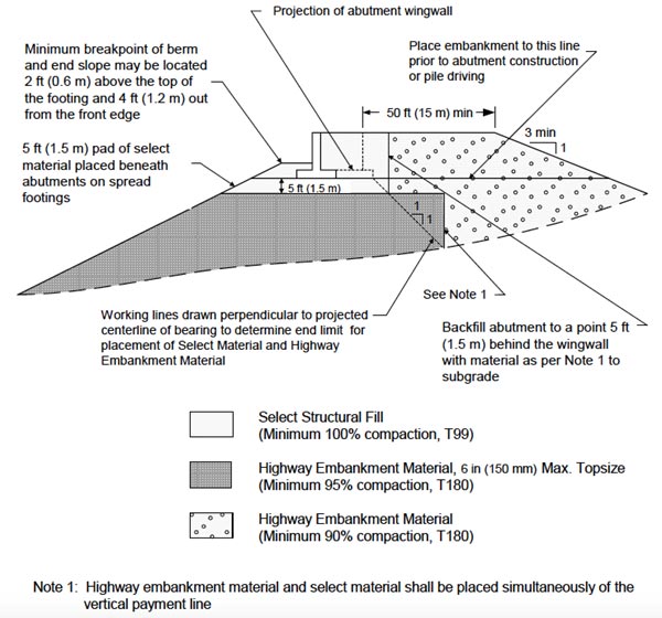
Special details and specifications are necessary when constructing a compacted structural fill to support a bridge foundation such as an abutment. Figure 1 shows the recommended details for construction of a structural approach embankment and bridge foundation. The material specifications are chosen so that the engineered fill material is capable of being compacted to a firm, non-yielding condition to support a bridge abutment spread footing. FHWA’s Geotechnical Engineering Circular No. 6: Shallow Foundations recommends that structural fill for highway embankment material should not include unsuitable or deleterious material such as peat, muck, wood, organic waste, coal, charcoal, or any other material that would perform poorly in an embankment.(12)

1 ft = 0.305 m
Figure 1. Illustration. Engineered fill details of structural approach road and bridge foundation.
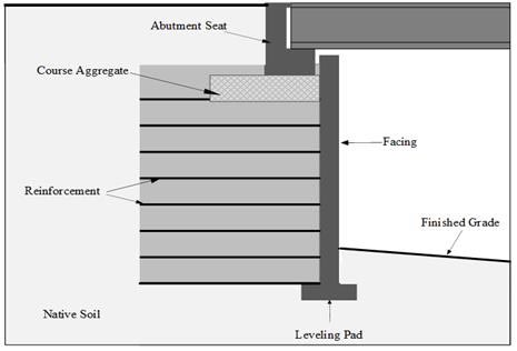
Since the first MSE abutment was constructed in the United States in 1974, MSE technology has been used in bridge-supporting structures such as bridge abutments, and both metallic and geosynthetic reinforcements have been used.(34) MSE abutments are MSE retaining walls subjected to much higher area loads that are located close to the wall face. Using MSE structures as direct support for bridge abutments can be a significant simplification in the design and construction of current bridge abutment systems and may lead to faster construction of highway bridge infrastructure. When a bridge beam is supported on a spread footing that bears directly on top of an MSE structure, this configuration is known as true MSE abutment, as shown in figure 2. To prevent overstressing the soil from the excess load exerted on a true MSE abutment, the beam seat is sized so that the centerline of bearing is at least 3.05 ft (1 m) behind the MSE wall face, and the service bearing pressure on the reinforced soil is no more than 4 kip/ft2 (192 kPa).(34) Anderson and Brabant reported that there are approximately 600 MSE abutments (300 bridges) built annually in the United States, of which 25 percent are true MSE abutments.(34)

Note: This figure was created by FHWA after Anderson and Brabant.(34)
Figure 2. Illustration. True MSE abutment types.
MSE abutments may result in construction cost savings where deep foundations are not needed. Additionally, the use of true bridge abutments can result in significant cost savings.(34) True bridge abutments also have significant advantages over conventional abutments. The proverbial bump at the end of the bridge is alleviated because the footing settles along with the MSE wall in contrast to a deep foundation that does not settle at the same rate. Additionally, approach slabs are not necessary because of the elimination of conditions that would lead to the bump at the end of the bridge, and the elimination of approach slabs results in significant cost savings.(7) While there are proven advantages of MSE abutments, there are some limits for their applicability, as with any technology. A study by Purdue University and the Indiana Department of Transportation revealed that MSE structures on shallow foundations should not be used as direct bridge abutments when soft soil layers, such as normally consolidated clays, are present near the surface where significant deformation and differential settlement are expected.(4) In such conditions, a design configuration including piles should be used. In more competent foundation profiles, MSE walls can be used for direct support of bridge abutments.
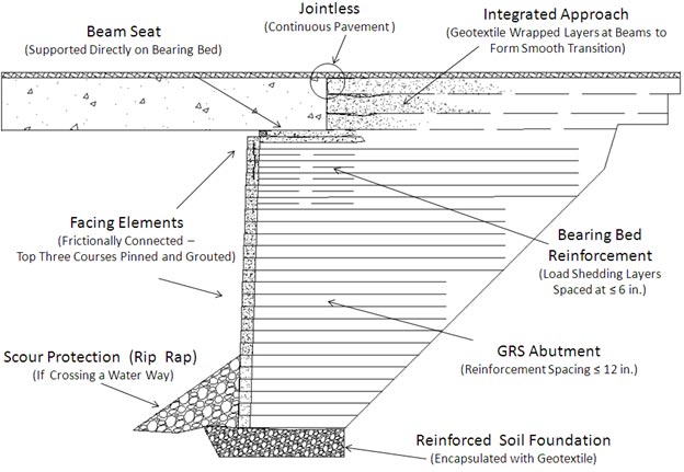
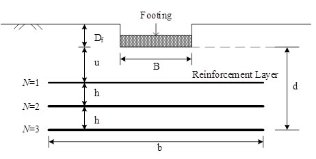
GRS technology consists of closely spaced layers of geosynthetic reinforcement and compacted granular fill material. GRS has been used for a variety of earthwork applications since the U.S. Forest Service first used it to build walls for roads in steep mountain terrain in the 1970s.(21) The spacing of GRS reinforcement should not exceed 12 inches (304.8 mm) and is typically 8 inches (203.2 mm).(21) As shown in figure 3, GRS-IBS typically includes an RSF, a GRS abutment, and a GRS integrated approach to transition to the superstructure. The RSF is composed of granular fill material that is compacted and encapsulated with a geotextile fabric. The application of GRS has several advantages: the system is easy to design and economically construct; it can be built in variable weather conditions with readily available labor, materials, and equipment; and it can easily be modified in the field.(21) Figure 4 shows an illustration of RSF and the common parameters used in RSF in this report.

1 inch = 25.4 mm
Figure 3. Illustration. Typical cross-section of GRS bridge abutment.

Figure 4. Illustration. Annotations of parameters of a shallow foundation on reinforced soil.
Where:
B = Width of foundation.
b = Length of reinforcement layers below foundation.
N = Number of reinforcement layers.
u = Embedment depth of top geogrid layer.
h = Spacing of reinforcing layers.
d = Depth of bearing bed reinforcement.
Df = Depth of embedment of foundation.