U.S. Department of Transportation
Federal Highway Administration
1200 New Jersey Avenue, SE
Washington, DC 20590
202-366-4000
Federal Highway Administration Research and Technology
Coordinating, Developing, and Delivering Highway Transportation Innovations
 |
| This report is an archived publication and may contain dated technical, contact, and link information |
|
Publication Number: FHWA-HRT-06-108
Date: May 2006 |
This edition of the Traffic Detector Handbook (the Handbook) is an updated version of the previous Handbook originally published as Implementation Package FHWA-IP-85-1, and supersedes the previous two editions. While the basic philosophy of the original document has been retained, the Handbook has been restructured and revised to update discussions of concepts and equipment that reflect the state of the practice, particularly as they relate to incorporation of new sensor and controller technologies in traffic management applications.
The overall objective of the Handbook is to provide a reference to assist the practicing engineer and technician in planning, designing, installing, and maintaining vehicle sensors that support traffic management on surface streets, arterials, and freeways. In accordance with this objective, the Handbook:
The objective of the Traffic Detector Handbook is to provide a single resource and basic reference for the design, installation, and maintenance of traffic flow sensors. |
The National Electrical Manufacturers Association (NEMA) Standards define a vehicle detection system as "...a system for indicating the presence or passage of vehicles." These systems provide traffic flow data for traffic-actuated signal control, traffic-responsive signal control, freeway surveillance and traffic management, and data collection systems.
The Traffic Detector Handbook describes the theory of operation, installation, and applications of in-roadway and over-roadway sensors. An in-roadway sensor is one that is placed as one of the following ways:
A traffic flow sensor is a device that indicates the presence or passage of vehicles and provides data or information that supports traffic management applications such as signal control, freeway mainline and ramp control, incident detection, and gathering of vehicle volume and classification data to meet State and Federal reporting requirements. |
By contrast, an over-roadway sensor is one that is mounted above the surface of the roadway in one of the following two ways:
Examples of in-roadway sensors include inductive-loop detectors, which are sawcut into the pavement; magnetometers, which may be placed underneath a paved roadway or bridge structure; and tape switches, which are mounted on the roadway surface. Examples of over-roadway sensors are video image processors that utilize cameras mounted on tall poles adjacent to the roadway or traffic signal mast arms over the roadway; microwave radar, ultrasonic, and passive infrared sensors mounted in a similar manner; and laser radar sensors mounted on structures that span the lanes to be monitored. Some emerging applications for wide area surveillance envision over-roadway sensors mounted on tall buildings and radio towers near the roadway and on aerial platforms.
Maximizing the efficiency and capacity of existing transportation networks is vital because of the continued increase in traffic volume and the limited construction of new highway facilities in urban, intercity, and rural areas. In the United States for example, highway miles traveled increased by 33 percent while public road mileage increased by less than 2 percent from 1987 to 1997.(1,2) Figure 1-1 shows the projected growth in U.S. highway demand to the year 2010 in terms of highway miles traveled per year.(2,3) The increase in demand, relative to the limited construction of new roads, has caused recurring congestion in the U.S. and throughout the industrialized world, as well as in developing nations.
|
Figure 1-1 shows the growth in U.S. highway demand from 2 trillion miles (mi) (3.2 trillion kilometers (km) in 1988, to 2.600 trillion mi (4.1 trillion km) in 1998, to a projection of over 3.3 trillion miles (5.3 trillion km) by 2010 in terms of highway miles traveled per year.(2,3) The increase in demand relative to capacity has caused recurring congestion. The annual growth is approximately linear. |

1 mile (mi) = 1.6 kilometers (km)
Figure 1-1. Growth in highway miles traveled in the United States.
The 2003–2010 trend is based on linear extrapolation of previous years' data.
Even when additional facilities are built to ease congestion and promote the use of multiple occupancy vehicles, the cost is often quite high. For example, the freeway-to-freeway high-occupancy vehicle (HOV) bypass structure, illustrated in Figure 1-2, costs approximately $150 million (U.S.) to construct. Construction and striping of HOV freeway lanes in Los Angeles County vary between $400,000 and $750,000 (U.S.) per lane mile ($640,000 to $1,200,000 per lane km), depending on the freeway configuration. Striping only costs $100,000 (U.S.) per lane mile ($160,000 per lane km). The latter estimates include costs associated with providing safety for the construction workers and building temporary roadbeds to maintain traffic flow during construction.
An alternative to expensive new highway construction is the implementation of strategies that promote more efficient utilization of current road, rail, air, and water transportation facilities. These strategies are found in Intelligent Transportation Systems (ITS) roadway and transit programs that have among their goals reducing travel time, easing delay and congestion, improving safety, and reducing pollutant emissions. ITS that contain electronic surveillance, communications, and traffic analysis and control technologies bring benefits to transportation system users and managers. Users gain from the information and guidance provided by ITS. Transportation managers and agencies profit from improved ability to monitor, route, and control traffic flows and disseminate information.
Figure 1-2 shows a freeway-to-freeway high occupancy vehicle (or HOV) bypass lane ramp structure under construction at intersection of CA–57 and CA–91 freeways in Anaheim, CA. HOV bypass lanes are a way of encouraging use of carpooling to reduce congestion. |
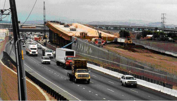
Figure 1 2. Freeway-to-freeway HOV bypass lane structure under construction at intersection of CA–57 and CA–91 freeways in Anaheim, CA
(Photograph courtesy of Lawrence A. Klein).
Millions of research and operations dollars are budgeted for managing traffic and alleviating congestion and delay on the Nation's existing streets and freeways. ITS applications for Advanced Traffic Management Systems, Advanced Traveler Information Systems, Commercial Vehicle Operations, Advanced Vehicle Control Systems, Advanced Public Transit Systems, and Archived Data User Services rely on traffic flow sensors to provide vehicle detection, incident detection, automatic traveler surveillance, real-time traffic adaptive signal control, archival data, and data for traveler, commercial, and emergency information services. The success of these intelligent transportation systems depends to a large extent on the proper design, installation, and maintenance of the sensor component of the overall system. Consequently, it is incumbent on the jurisdictions or agencies implementing or operating ITS to assure that appropriate attention is directed toward this relatively straightforward, but critical system element.
In the 1920s, when manually operated traffic signals were being replaced by automatic, pretimed traffic signal control devices, engineers soon realized they needed a method to collect the traffic data previously obtained visually by the police officer on duty. Among those concerned was Charles Adler, Jr., of Baltimore, MD, a railway signal engineer. He developed a sensor that was activated when a driver sounded his car horn at an instrumented location. This device consisted of a microphone mounted in a small box on a nearby utility pole. First installed in 1928 at a Baltimore intersection, Adler's device enabled the first semiactuated signal installation to assign right-of-way by means of a vehicle sensor.
Charles Adler, Jr., of Baltimore, MD, developed the first traffic sensor based on detecting acoustic energy from the vehicle's horn. |
At nearly the same time, Henry A. Haugh, an electrical engineer, developed an in-roadway pressure-sensitive sensor, utilizing two metal plates that acted as electrical contacts. The wheel pressure of passing vehicles brought the plates together. This pressure-sensitive, treadle type sensor proved more popular than the horn-activated sensor. In fact, this sensor enjoyed widespread use for over 30 years as the primary means of detecting vehicles at actuated signals.
Adler continued his work with sound detectors and in 1931 introduced another sound detector, which employed hollow steel boxes embedded in the intersection approach. These boxes picked up the sound of passing wheels, which was transmitted to microphones.
Mechanical problems with the contact-plate sensor led to the introduction of the electro-pneumatic sensor. Although this device found some application, it was costly to install, capable of only passage (motion) detection, and its (axle) counting accuracy was limited by the generation of air pressure waves and capsule contact bounce.
|
The first vehicle passage sensor used a pressure-sensitive device. |
In retrospect, it seems unfortunate that the treadle detector, which utilized the most obvious and most easily detected property of vehicles—their weight—could not be economically produced. Snow plows could lift the plate from the roadway, resulting in costly repairs. There was also the expense of reinstalling the detector after roadway resurfacing. These problems led to the search for traffic flow sensors based on more subtle properties such as:
Not all of these concepts have been commercially exploited. Today, the inductive-loop detector is, by far, the most widely used sensor in modern traffic control systems. Magnetometers, magnetic sensors, video image processors, microwave and laser radar sensors, ultrasonic, acoustic, and passive infrared sensors are also produced commercially and used for various traffic management applications. The optical sensor has found use for detecting priority and overheight vehicles.
While single inductive-loop detectors give direct information concerning vehicle passage and presence, other traffic flow parameters such as density and speed must be inferred from algorithms that interpret or analyze the measured data. When these parameters are calculated from inductive loop data, the values may not have sufficient accuracy for some applications (such as rapid freeway incident detection) or the available information may be inadequate to support the application (such as calculation of link travel time). Furthermore, the operation of inductive-loop detectors is degraded by pavement deterioration, improper installation, and weather-related effects. Street and utility repair may also impair loop integrity. Thus, a good loop installation, acceptance testing, repair, and maintenance program is required to maintain the operational status of an inductive-loop-based vehicle detection system.
Evaluations of modern over-roadway sensors show that they provide an alternative to inductive-loop detectors. The traffic flow parameters measured with over-roadway sensors satisfy the accuracy requirements of many current freeway and surface street applications, provided suitable mounting is available. The mounting location must provide an unobstructed view of vehicles for optimum performance. In general, when sensors are installed over the lane of traffic they are intended to monitor, their view and hence their data collection ability is not occluded by other vehicles that are present within the viewing area of the sensor. Over-roadway sensors that are mounted on the side of a roadway and view multiple lanes of traffic at angles perpendicular to or at an oblique angle to the flow direction may experience two types of data anomalies. The first occurs when tall vehicles block the sensor's view of distant lanes. The occlusion may potentially cause an undercount or false average speed measurement. The second anomaly occurs when tall vehicles project their image into adjacent lanes. When a sensor is sensitive to this effect, it will overcount and again may report a misleading average speed. Thus, sensor type, mounting height and location, vehicle mix, road configuration, and sensor viewing angles must be analyzed with respect to the intended application. Some over-roadway sensors may be more susceptible to these anomalies than others.
Installation and maintenance of over-roadway sensors mounted over the traffic lanes they monitor may require lane closure for bucket trucks to be parked on the mainline. This can disrupt traffic and pose a safety risk to the installers. Traffic should be managed in accordance with "Part 6—Temporary Traffic Control," as found in the Manual on Uniform Traffic Control Devices (MUTCD).(4)
Most over-roadway sensors have relay or solid state outputs that are compatible with systems that accept inductive loop data. Some also have serial outputs that directly provide multilane traffic volume, occupancy, speed, vehicle length, and classification that are not ordinarily available from inductive-loop detectors. As there are presently no generally accepted standards for serial data formatting, software code called drivers must be written before the serial data stream can be decoded by the field controller or central computer at a traffic management center. A standard National Transportation Communications for ITS Protocol (NTCIP) protocol is needed to ameliorate this situation.
|
The issue of how to handle sensor data more intelligently rather than as simple contact closures is now beginning to be addressed by researchers. See especially the work with NCHRP 3-66 "Traffic Signal State Transition Logic Using Enhanced Sensor Information" and Small Business Innovative Research Project DTRS57-03-R-SBIR "Real Time Linux Operating System Software for Advanced Traffic Controller to Host Traffic Control Software." |
An emerging potential source of traffic flow data is from cellular telephone companies who monitor the transmitting status of telephones that are engaged in conversations in support of the wireless enhanced all automatic location identification (ALI) directive of the Federal Communications Commission (FCC). This directive mandates providing the caller's location to within:
The location of these telephones can potentially be made available to traffic management agencies to anonymously track vehicles on a noncooperative basis. This information can assist in estimating congestion and travel time over wide areas, while protecting the identity of the telephone subscriber. This method of gathering traffic flow data is outside the scope of the handbook and, therefore, will not be discussed further.
Another unconventional source of traffic monitoring data is from non-stationary and airborne platforms. Information gathered from satellite, aircraft, and unmanned aerial vehicles can be used to estimate arterial and freeway traffic characteristics over long time scales and large geographic areas, including those where data were previously unavailable. The spatial coverage provided from air- and satellite-based sensors can potentially support the development of new metrics that better represent highway utilization and congestion.
Although the installation and maintenance of in-roadway sensors such as inductive-loop and magnetic field sensors can disrupt traffic and pose a safety risk to the installers, a requirement for in-roadway sensors continues for several reasons. These include aesthetic considerations that dictate their use for traffic management when over-roadway sensors are excluded from consideration, axle counting and weigh-in-motion applications requiring sensors (such as pneumatic tubes, fiber-optic, bending plates, piezoelectric, pressure sensitive resistance, load cells, and capacitance mats) under or on the road surface, cost and safety issues associated with mounting over-roadway sensors where existing structures are not available, and policy that prohibits over-roadway sensors in certain locations. Newly installed inductive-loop detectors may also provide more accurate data than over-roadway sensors when they are coupled with advanced electronics units available from several manufacturers. Sensors used in weigh-in-motion applications are not described in this Handbook, but information concerning their operation and installation may be found elsewhere.(5,6)
Table 1-1 compares the strengths and weaknesses of current sensor technologies with respect to installation, parameters measured, and performance in inclement weather, variable lighting, and changeable traffic flow. Most over-roadway sensors are compact and mounted above or to the side of the roadway, making installation and maintenance relatively easy. Some sensor installation and maintenance applications may require the closing of the roadway to normal traffic to ensure the safety of the installer and motorist. All the sensors listed operate under day and night conditions.(5)
Table 1-2 lists the types of data typically available from each sensor technology, coverage area, communication bandwidth requirements, and purchase costs.
Several technologies are capable of supporting multiple lane, multiple detection zone applications with one or a limited number of units. These devices may be cost effective when larger numbers of detection zones are needed to implement the traffic management strategy.
A low to moderate communication bandwidth is indicated if only data and control commands are transmitted between the sensor, controller, and traffic management center. Larger bandwidth is required if real-time video imagery is transmitted at 30 frames/second (s). The requirement for large bandwidth communications media such as T1 telephone lines, which support transmission rates of 1.544 x 106 bits/s (baud) at a bandwidth of 125 Megahertz (MHz), and fiber can be reduced if compressed imagery (e.g., transmission rates of 256,000 bits/s at a bandwidth of 20.5 MHz) is suited for the application. The required transmission rate increases when large numbers of sensors, roadside information devices such as changeable message signs and highway advisory radio, signal timing plans, and traveler information databases are used to implement traffic management strategies.
The range of purchase costs for a particular sensor technology reflects cost differences among specific sensor models and capabilities. If multiple lanes are to be monitored and a sensor is capable of only single lane operation, then the sensor cost must be multiplied by the number of monitored lanes.
|
Table 1-1 summarizes the strengths and weaknesses of inductive loop, magnetometer, microwave radar, active infrared, passive infrared, ultrasonic, acoustic, and video image processor sensors. |
| Technology | Strengths | Weaknesses |
|---|---|---|
| Inductive loop |
|
|
| Magnetometer (two-axis fluxgate magnetometer) |
|
|
| Magnetic (induction or search coil magnetometer) |
|
|
| Microwave radar |
|
|
| Active infrared (laser radar) |
|
|
| Passive infrared |
|
|
| Ultrasonic |
|
|
| Acoustic |
|
|
| Video image processor |
|
|
| The good performance of in-roadway sensors such as inductive loops, magnetic, and magnetometer sensors is based, in part, on their close location to the vehicle. Thus, they are insensitive to inclement weather due to a high signal-to-noise ratio. Their main disadvantage is their in-roadway installation, necessitating physical changes in the roadway as part of the installation process. Over-roadway sensors often provide data not available from in-roadway sensors and some can monitor multiple lanes with one unit. |
| Sensor technology | Count | Presence | Speed | Output data | Classification | Multiple lane, multiple detection zone data | Communication bandwidth | Sensor purchase costa (each in 1999 U.S. $) |
|---|---|---|---|---|---|---|---|---|
| Inductive loop | Low to moderate | Lowi ($500–$800) | ||||||
| Magnetometer (two axis fluxgate) | Low | Moderatei ($900–$6,300) | ||||||
| Magnetic induction coil | Low | Low to moderatei ($385–$2,000) | ||||||
| Microwave radar | Moderate | Low to moderate ($700–$2,000) | ||||||
| Active infrared | Low to moderate | Moderate to high ($6,500–$3,300) | ||||||
| Passive infrared | Low to moderate | Low to moderate ($700–$1,200) | ||||||
| Ultrasonic | Low | Low to moderate (Pulse model: $600–$1,900) | ||||||
| Acoustic array | Low to moderate | Moderate ($3,100–$8,100) | ||||||
| Video image processor | Low to highh | Moderate to high ($5,000–$26,000) | ||||||
| a Installation, maintenance, and repair costs must also be included to arrive at the true cost of a sensor solution as discussed in the text. | ||||||||
| b Speed can be measured by using two sensors a known distance apart or estimated from one sensor, the effective detection zone and vehicle lengths. | ||||||||
| c With specialized electronics unit containing embedded firmware that classifies vehicles. | ||||||||
| d With special sensor layouts and signal processing software. | ||||||||
| e With microwave radar sensors that transmit the proper waveform and have appropriate signal processing. | ||||||||
| f With multidetection zone passive or active mode infrared sensors. | ||||||||
| g With models that contain appropriate beamforming and signal processing. | ||||||||
| h Depends on whether higher-bandwidth raw data, lower-bandwidth processed data, or video imagery is transmitted to the TMC. | ||||||||
| i Includes underground sensor and local detector or receiver electronics. Electronics options are available to receive multiple sensor, multiple lane data. | ||||||||
| Table 1-2 lists traffic flow sensor technologies and their capabilities. Most measure count, presence, and occupancy. Some single detection zone sensors, such as the range-measuring ultrasonic sensor and some infrared sensors, do not measure speed. CW Doppler radar sensors do not detect stopped or slow moving vehicles. Magnetometer, magnetic, passive infrared and sound-based, acoustic sensor models do not classify vehicles. |
Direct hardware and software purchase costs are not the only costs associated with a sensor. Installation, maintenance, and repair should also be factored into the sensor selection decision. Installation costs include fully burdened costs for technicians to prepare the road surface or subsurface (for inductive loops or other surface or subsurface sensors), install the sensor and mounting structure (if one is required for over-roadway sensors), purchase and install conduit, close traffic lanes, divert traffic, provide safety measures where required, and verify proper functioning of the device after installation is complete. Environmental concerns may warrant providing for the removal of cutting water and debris from the site. Maintenance and repair issues are discussed in Chapter 6.
The technologies listed in Tables 1-1 and 1-2 are mature with respect to traffic management applications, although some may not provide the data required for a specific application. Some technologies, such as video image processing, microwave and laser radars, and inductive-loop detectors, continue to evolve by adding capabilities that measure additional traffic parameters, track vehicles, improve spatial resolution, or link data from one sensor to those from another.
The following discussion provides a broad overview of the operation of in-roadway and over-roadway traffic flow sensors most used today. These sensors include inductive-loop detectors, magnetometers, video image processors, microwave radar sensors, laser radar sensors, passive infrared sensors, ultrasonic sensors, and passive acoustic sensors. Typical applications include traffic signal control, freeway ramp metering, freeway mainline control, incident detection, and gathering of vehicle volume and classification data to meet State and Federal reporting requirements. These devices are either installed in, below, or above the roadway. Subsequent chapters of the Handbook describe the installation and operation of these sensors in more detail.
An inductive-loop detector senses the presence of a conductive metal object by inducing currents in the object, which reduce the loop inductance. Inductive-loop detectors are installed in the roadway surface. They consist of four parts: a wire loop of one or more turns of wire embedded in the roadway pavement, a lead-in wire running from the wire loop to a pull box, a lead-in cable connecting the lead-in wire at the pull box to the controller, and an electronics unit housed in the controller cabinet as shown in Figure 1-3. The electronics unit contains an oscillator and amplifiers that excite the embedded wire loop. The electronics unit also supports other functions such as selection of loop sensitivity and pulse or presence mode operation to detect vehicles that pass over the detection zone of the loop.
|
Inductive-loop detectors sense the presence of a conductive metal object by inducing electrical currents in the object. The induced current decreases the loop inductance, which is sensed by the inductive-loop electronics unit. The electronics unit interprets the decreased inductance as a vehicle detection and sends an appropriate call to the controller. |
Figure 1-3. Inductive-loop detector system.
| Figure 1-3 illustrates an inductive-loop detector system consisting of one or more turns of wire laid in a loop in the roadway, which is connected by lead-in wire to a pull box located at the side of the road. The pull box, in turn, is connected by lead-in cable to an electronics unit in a cabinet. The electronics unit energizes the wire loop, analyzes the signal, and transmits vehicle detection information to the controller. |
When a vehicle passes over the wire loop or is stopped within the area enclosed by the loop, it reduces the loop inductance, which unbalances the tuned circuit of which the loop is a part. The resulting increase in oscillator frequency is detected by the electronics unit and interpreted as a vehicle detection by the controller.
Conventional inductive loops are constructed by cutting a slot in the pavement and placing one or more turns of wire in the slot as indicated in Figure 1-4. The wire is then covered with sealant.
The size, shape, and configuration of the loop vary depending upon the specific application, ranging from the common 6- x 6-ft (1.8- x 1.8-m) loops, to long rectangular loops 6- x 40- to 70-ft (1.8- x 12- to 21-m) for actuated signal control. Because of the flexibility of its design, the inductive-loop detector is capable of detecting a broad range of vehicles.
An alternate, more durable construction is to place the turns of wire in a plastic conduit just below the pavement surface. Another option is to encase the wire in a plastic sleeve before installing the wire loop in the sawcut slot in the pavement. A wide variety of loop sizes and shapes are available to meet specific needs as described in Chapter 4.
Figure 1-4 depicts an inductive-loop detector installation, which contains a 3-turn 6- x 6-ft (1.8- x 1.8-m) square loop and connecting wire and cable. The loop is centered in a 12-ft (3.7 m) roadway, 3 ft (0.9 m) from either side. |
Figure 1 4. Inductive-loop installation example.
Magnetic sensors are passive devices that detect the presence of a ferrous metal object through the perturbation (known as a magnetic anomaly) they cause in the Earth's magnetic field. Figure 1-5 shows the magnetic anomaly created by the magnetic dipoles, i.e., energy fields, on a steel vehicle when it enters a magnetometer's detection zone. The upper part of Figure 1-5 indicates how the vector addition of the dipole magnetic field to the quiescent Earth's magnetic field produces the magnetic anomaly. The lower portion of the figure depicts several dipoles on a vehicle and their effect on compass readings and sensor output.
Figure 1-5. Magnetic anomaly in the Earth's magnetic field induced by magnetic dipoles in a ferrous metal vehicle.
Two types of magnetic field sensors are used for traffic flow parameter measurement. The first type, the two-axis fluxgate magnetometer, detects changes in the vertical and horizontal components of the Earth's magnetic field produced by a ferrous metal vehicle. The two-axis fluxgate magnetometer contains two primary windings and two secondary "sense" windings on a bobbin surrounding a high permeability soft magnetic material core. In response to the magnetic field anomaly, i.e., the magnetic signature of a vehicle, the magnetometer's electronics circuitry measures the output voltage generated by the secondary windings. The vehicle detection criterion is for the voltage to exceed a predetermined threshold. In the presence or stopped vehicle mode of operation, the detection output is maintained until the vehicle leaves the detection zone.(5)
The second type of magnetic field sensor is the magnetic detector, more properly referred to as an induction or search coil magnetometer. It detects the vehicle signature by measuring the distortion in the magnetic flux lines induced by the change in the Earth's magnetic field produced by a moving ferrous metal vehicle. These devices contain a single coil winding on a permeable magnetic material rod core. Similar to the fluxgate magnetometer, magnetic detectors generate a voltage when a moving ferromagnetic object perturbs the Earth's magnetic field. Induction magnetometers do not detect stopped vehicles since they require a vehicle to be moving or otherwise changing its signature characteristics with respect to time. However, multiple units of some magnetic detectors can be installed and utilized with specialized signal processing software to generate vehicle presence data.
Magnetic detectors are inserted horizontally below the roadway. Since they provide only passage data and not occupancy or presence data, their use is limited to special applications.
Another device similar to the magnetic detector is the microloop probe. As a vehicle passes over the microloop, the change in inductance is sensed by a conventional inductive-loop detector electronics unit. Some models are inserted into holes bored into the roadway surface. Other models are inserted into sleeves below the road surface using horizontal drilling from the side of the road. Often two or more microloop probes are connected in series or with conventional wire loops to detect a range of vehicle sizes and obtain required lane coverage. One microloop probe model can be connected in rows of three to generate signals that detect stopped vehicles. Application-specific software from its manufacturer is also needed to enable stopped vehicle detection.
Video cameras were introduced to traffic management for roadway surveillance based on their ability to transmit closed-circuit television imagery to a human operator for interpretation. Present-day traffic mangers utilize video image processing to automatically analyze the scene of interest and extract information for traffic surveillance and management. A video image processor (VIP) system typically consists of one or more cameras, a microprocessor-based computer for digitizing and analyzing the imagery, and software for interpreting the images and converting them into traffic flow data. A VIP can replace several in-ground inductive loops, provide detection of vehicles across several lanes, and perhaps lower maintenance costs. Some VIP systems process data from more than one camera and further expand the area over which data are collected.
|
Video image processors (VIPs) detect vehicles and provide traffic flow data across several lanes and in multiple areas in one lane. They require a line-of-sight view of the area they monitor and are subject to occlusion and the effects of inclement weather. |
VIPs can classify vehicles by their length (usually three length classification ranges are available) and report vehicle presence, volume, lane occupancy, and speed for each class and lane. VIPs that track vehicles may also have the capability to register turning movements and lane changes. Vehicle density, link travel time, and origin-destination pairs are potential traffic parameters that can be obtained by analyzing data from a series of image processors installed along a section of roadway.(5) The types of information provided by VIPs makes suitable for arterial and freeway applications. An example of a camera mounted to transmit imagery to a VIP for an arterial traffic signal control application is shown in Figure 1-6.
VIP systems detect vehicles through the analysis of black and white or color imagery gathered by cameras at a section of roadway. Black and white image analysis is performed by algorithms that examine the variation of gray levels in groups of pixels (picture elements) contained in the video frames. Research has been conducted on algorithms that are sensitive to color features, for example those that assist in eliminating shadow artifacts or enhance vehicle discrimination in inclement weather. Along with vehicle size and class data, color fingerprints or signatures have been proposed to determine traffic volume, lane changes, turning movements, and link travel time by re-identifying a vehicle or group at a downstream site.(7,8)
|
Figure 1-6 shows a camera in a weatherproof housing mounted on a vertical pole that extends upright from a signal mast arm. |
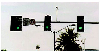
Figure 1-6. Overhead camera mounting on a mast arm as typically used to provide imagery to a VIP for arterial signal control
(Photograph courtesy of Lawrence A. Klein).
Algorithms utilized in video image processing are designed to ignore gray level or color variations in the stationary image background. The algorithms are intended to also ignore variations caused by weather conditions, shadows, and daytime or nighttime artifacts, but retain objects identified as automobiles, trucks or buses, motorcycles, and bicycles. Traffic flow parameters are calculated by analyzing successive video frames.
Microwave radar was developed for detecting objects in the period before and during World War II. Radar is defined as "a device for transmitting electromagnetic signals and receiving echoes from objects of interest (i.e., targets) within its volume of coverage."(9) Radar was originally an acronym for RAdio Detection And Ranging.
The term microwave refers to the wavelength of the transmitted energy, usually between 0.4 inch and 11.8 inches (1 and 30 centimeters (cm)). This corresponds to a frequency range of 1 gigahertz (GHz (109 Hertz (Hz)) to 30 GHz 109 Hz. Microwave sensors designed for traffic data collection in U.S. roadside applications are limited by FCC regulations to operating frequency intervals near 10.5, 24.0, and 34.0 GHz. The sensor manufacturers satisfy these requirements, as well as others that restrict the transmitted power and bandwidth. Thus, the end users are not required to possess special licenses or test equipment to verify the output frequency or power of the devices. Radars at frequencies above 30 GHz operate in the millimeter-wave spectrum since the wavelength of the transmitted energy is expressed in terms of millimeters (mm). Most commercially available microwave radar sensors utilized in roadside applications transmit electromagnetic energy at the X-band frequency of 10.525 GHz. Higher frequencies illuminate smaller ground areas with a given size antenna and thus are capable of greater spatial resolution. FCC-approved frequencies for vehicle-mounted radars utilized in collision avoidance, obstacle detection, and automatic cruise control are 47.5 to 47.8 GHz and 76 to 77 GHz.
Figure 1-7 shows the transmission of energy by an overhead-mounted microwave radar toward an area of roadway. The beamwidth or area in which the radar energy is concentrated is controlled by the size and the distribution of energy across the aperture of the antenna. The sensor manufacturer usually establishes these design constraints. When a vehicle passes through the antenna beam, a portion of the transmitted energy is reflected back towards the antenna. The energy then enters a receiver where the detection is made and traffic flow data, such as volume, speed, and vehicle length, are calculated.
Figure 1-7. Microwave radar operation.
|
Figure 1-7 shows that a microwave radar mounted on overhead bridges, poles or mast arms transmits signals that are reflected off vehicles back to the radar sensor. The reflected energy is analyzed to produce traffic flow data. |
The radar sensor may be mounted over the middle of a lane to measure approaching or departing traffic flow parameters in a single lane, or at the side of a roadway to measure traffic parameters across several lanes as shown in Figure 1-8. Forward-looking wide beamwidth radars gather data representative of traffic flow in one direction over multiple lanes. Forward-looking narrow beamwidth radars monitor a single lane of traffic flowing in one direction. Side-mounted, multiple detection zone radars project their detection area (i.e., footprint) perpendicular to the traffic flow direction. These sensors provide data corresponding to several lanes of traffic, but generally not as accurately as can the same radar mounted in the forward-looking direction. Side-mounted, single detection zone radars are typically used to detect vehicle presence in one or more lanes at signalized intersections.(5)
Figure 1-8. Mounting of presence-detecting microwave radar sensors for multilane vehicle detection and signal actuation at an intersection
(Picture courtesy of EIS, Toronto, Canada).
Microwave sensors that transmit a continuous wave (CW) Doppler waveform detect vehicle passage and provide measurements of vehicle count and speed. They cannot detect stopped vehicles. Microwave sensors that transmit a frequency modulated continuous wave (FMCW) detect vehicle presence as well as vehicle passage. They can detect stopped vehicles and provide measurements of lane occupancy, vehicle count, speed, and vehicle length grouped into several length bins.
|
Figure 1-8 shows that presence-detecting microwave radar sensors can detect traffic flow in multiple lanes when mounted on poles adjacent to pedestrian crosswalks or roadway shoulders. |
Active and passive infrared sensors are manufactured for traffic flow monitoring applications. Active infrared sensors illuminate detection zones with low power infrared energy transmitted by laser diodes operating in the near infrared region of the electromagnetic spectrum at 0.85 mm. A portion of the transmitted energy is reflected or scattered by vehicles back towards the sensor. Although light-emitting diodes may also be utilized as the energy source in an active IR sensor, there are currently no commercial models marketed in the U.S. that exploit this design. A prototype sensor system using modulated light emitting diodes was designed to measure the speed and height of high and long trucks entering a curved freeway-to-freeway interchange. The diodes operated in the near infrared spectrum at 880 nanometers (nm). The signal modulation prevented interference from other sources of infrared energy, including sunlight. Two transmitter-receiver systems measured the vehicle speed and one measured the vehicle height. When trucks susceptible to rollover or jackknifing were encountered, flashers were activated to warn drivers to reduce speed.(5,10)
Passive sensors transmit no energy of their own. Rather they detect energy from two sources:
|
Passive infrared sensors transmit no energy of their own. Rather they detect energy emitted from roadways and vehicles or energy that is reflected from them. |
The energy captured by active and passive infrared sensors is focused by an optical system onto an infrared-sensitive material mounted at the focal plane of the optics. This material converts the reflected and emitted energy into electrical signals. Real-time signal processing is used to analyze the signals for the presence of a vehicle. The sensors are mounted overhead to view approaching or departing traffic. They can also be mounted in a side-looking configuration. Infrared sensors are utilized for signal control; volume, speed, and class measurement; detection of pedestrians in crosswalks; and transmission of traffic information to motorists.
Laser radars are active sensors in that they transmit energy in the near infrared spectrum. Models are available that scan infrared beams over one or two lanes or use multiple laser diode sources to emit a number of fixed beams that cover the desired lane width. An example of a laser radar beam-scanning configuration is shown in Figure 1-9. Laser radars provide vehicle presence at traffic signals, volume, speed, length assessment, queue measurement, and classification. Multiple units can be installed at the same intersection without interference from transmitted or received signals. Modern laser sensors produce two- and three-dimensional imagery of vehicles suitable for vehicle classification as illustrated in Figure 1-10. Their ability to classify 11 types of vehicles has found application on toll roads.
|
A laser radar is an active infrared sensor, since it transmits energy in the infrared spectrum. Figure 1-9 depicts a scanning laser radar mounted over a lane. This mounting configuration optimizes the sensor's view of vehicular traffic flow. |
Figure 1-9. Scanning infrared laser radar two-beam pattern across a traffic lane
(Drawing courtesy of Schwartz Electro-Optics, now OSI Laserscan, Orlando, FL).
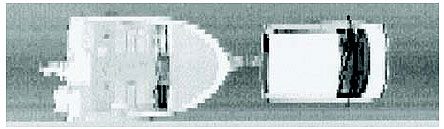
Figure 1-10. 3-D laser radar range image of a van pulling a boat
(Photograph courtesy of Schwartz Electro-Optics, now OSI Laserscan, Orlando, FL).
In addition to the technologies discussed above, others find application to traffic management. These include ultrasonic sensors, passive acoustic sensors, and devices that use a combination of sensor technologies. These devices are described further in Chapter 2. Chapter 2 also discusses the operation of passive infrared sensors in more detail.
|
Although not discussed in this chapter, other sensor technologies find application in traffic management. These include ultrasonic sensors, passive acoustic sensors, and devices that use a combination of sensor technologies. |
Traffic sensor literature often uses different terms to describe the same traffic flow sensors or their characteristics. To reduce potential confusion, the terms utilized in this Handbook are defined below. Words or phrases having the same meaning are listed along with the primary word being defined. Additional terms are defined in the glossary that appears in Appendix P.
Crosstalk: The adverse interaction of any channel of a sensor or sensor electronics unit with any other channel in that or another device. Crosstalk can occur via mutual coupling of magnetic fields in nearby inductive loops. The mutual coupling causes an interaction between two or more electronics units in the same cabinet when the units operate at the same or nearby frequencies. Crosstalk results in a sensor output actuation in the absence of a vehicle.
Detector Electronics Unit (Electronics Unit, Sensor Electronics Unit, Amplifier): An electronic device that energizes an inductive-loop detector, monitors loop inductance, and responds to a predetermined decrease in inductance with outputs that indicate the passage or presence of vehicles in the detection zones (NEMA).
An inductive-loop detector electronics unit is sometimes called an amplifier or detector, although it performs other functions as well, e.g., sensitivity adjustment, failure indication, and delayed actuation of controlled signals. Electronics units are also used with magnetic detectors and magnetometers. The electronics unit is typically located in a controller cabinet.
Detection Zone (Area of Detection, Detection Area, Zone of Detection, Effective Loop Area, Field of Influence, Field of View, Sensing Zone, Footprint): The area of the roadway within which a vehicle is detected by a sensor system.
Inductive-loop Detector (Loop Detector System): A sensor capable of detecting vehicle passage and presence. It consists of four parts, namely one or more turns of wire embedded in the pavement, a lead-in wire running from the wire loop in the pavement to the pull box, a lead-in cable spliced to the lead-in wire at the pull box, which connects to the controller, and an electronics unit housed in the controller.
Fluxgate Magnetometer: Two-axis fluxgate magnetometers are sensors that detect changes in the vertical and horizontal components of the Earth's magnetic field produced by a ferrous metal vehicle. They detect moving and stopped vehicles and thus provide passage and presence information.
Large Area Sensor (Area Sensor): For inductive-loop detectors utilized for traffic signal actuation, it is an inductive loop or combination of inductive loops connected in series, parallel, or series and parallel covering an area in the approach to an intersection. Detection area varies from 6 x 40 ft (1.8 x 12 m) to 6 x 100 ft (1.8 x 30 m) or larger. One of the more common configurations is four 6- x 6-ft (1.8- x 1.8-m) loops spaced 9 or 10 ft (2.75 or 3 m) apart for a length of 51 or 54 ft (15.5 or 16.5 m).
Lead-In Cable (Feeder Cable, Home-Run Cable, Transmission Line): The electrical cable that is spliced to the lead-in wire in the pull box and connects to the input of the inductive-loop detector electronics unit.
Lead-In Wire: That portion of an inductive-loop wire between the physical edge of the loop and the pull box. For a magnetic detector and magnetometer, it is the wire that runs from the sensor (probe) to the pull box.
Magnetic Detector (Induction or Search Coil Magnetometer): A passive device that detects changes in the Earth's magnetic field caused by the movement of a ferrous-metal vehicle in or near its detection area. It is placed under or in the roadway to detect the passage of a vehicle over the sensor. These sensors generally detect only moving vehicles. Their output is connected to an electronics unit.
Magnetic Sensor: Passive devices that detect the presence of a ferrous metal object through the perturbation (known as a magnetic anomaly) it causes in the Earth's magnetic field. Its output is connected to an electronics unit. The two types of magnetic sensors are fluxgate magnetometers and induction magnetometers, also referred to as magnetic detectors in this Handbook.
Passage Sensor (Motion Detector, Motion Sensor, Dynamic Detector, Movement Detector): A traffic flow sensor that detects the passage of a vehicle moving through the detection zone and ignores the presence of a vehicle stopped within the detection zone.
Presence Sensor: A traffic flow sensor that detects the presence of a vehicle within its detection zone and holds the call for a specified minimum time.
Pull Box: (Hand Hole, Junction Box, Junction Well, Splice Box): A container usually at least 1 cubic foot (e.g., approximately 1 ft3 (0.028 m3)) in size that is placed underground with a removable cover flush with the ground surface. Splices between lead-in cable and loop lead-in wire are located here.
Sensor: A device for indicating the presence or passage of vehicles or pedestrians. This general term is usually supplemented with a modifier indicating type (e.g., inductive-loop detector, magnetic detector, video image processor, microwave sensor, and infrared sensor); operation (e.g., point sensor, large area sensor, and presence sensor); or function (e.g., calling sensor, extension sensor, and classification sensor).
Sensor Amplifier: A device capable of intensifying the electrical energy or signal produced by a sensor. An example is a magnetic detector amplifier. An inductive-loop detector electronics unit is sometimes called an amplifier, although it performs other functions in addition to signal amplification.
Small Area Sensor (Point Sensor): A sensor that detects vehicles at a spot location, i.e., a small area usually not exceeding 6 x 6 ft (1.8 x 1.8 m).
Splashover: An unwanted actuation caused by a vehicle in a lane adjacent to that in which the sensor is located.
The Traffic Detector Handbook is structured to parallel the progression of decisions, activities, and functions related to the design, installation, and maintenance of sensor systems. Chapter 1 addresses the need for sensors as an integral part of modern traffic control and management systems and discussed the operation of several of the sensor technologies currently exploited for traffic management.
Chapter 2 describes the theory of operation of the inductive-loop detector, magnetometer, video image processor, microwave radar sensor, laser radar sensor, passive infrared sensor, ultrasonic sensor, passive acoustic sensor, and other sensors that utilize a combination of technologies. It addresses the needs of traffic and electrical engineers who have responsibility for selecting or specifying sensors that meet specific operational requirements. It also describes the NEMA Standards and the Type 170 and 2070 Controller Specifications.
Chapter 3 provides an overview of traffic control and management applications that rely on vehicle detection and monitoring of environmental conditions. It identifies how sensors support these applications.
The design and operating characteristics of in-roadway sensors such as inductive loops, magnetometers, and magnetic detectors for surface street and freeway traffic management are discussed in Chapter 4. This topic should be of particular interest to traffic engineers who develop plans and specifications for local intersections, traffic signal systems, and freeway surveillance and control systems.
Chapter 5 illustrates the installation procedures and best current practices for in-roadway and above-roadway sensors. The information is directed toward project engineers, contractors, inspectors, field crew supervisors, and traffic technicians.
Chapter 6 describes the broad spectrum of maintenance activities associated with in-roadway and over-roadway sensors. It provides management and supervising engineers with information needed to identify and resolve maintenance-related issues. The chapter contains detailed guidelines for maintenance supervisors and technicians to assist in identifying sensor failure mechanisms and corresponding corrective actions.
The appendices provide additional detailed information concerning several of the topics discussed in the main body of the Handbook.
FHWA-HRT-06-108

