U.S. Department of Transportation
Federal Highway Administration
1200 New Jersey Avenue, SE
Washington, DC 20590
202-366-4000
Federal Highway Administration Research and Technology
Coordinating, Developing, and Delivering Highway Transportation Innovations
 |
| This report is an archived publication and may contain dated technical, contact, and link information |
|
Publication Number: FHWA-HRT-06-139
Date: October 2006 |
This appendix describes the calculation of the electrical characteristics of twisted lead-in wire composed of Belden #14 AWG copper conductor wire. The wire size and spacing definitions are shown in Figure D-1. Here, D represents the distance between the center of the wire cores in the twisted pair and d is the diameter of the wire core.

Figure D-1.Wire spacing and size definitions used in wire inductance and capacitance calculations.
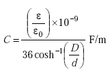
The capacitance C of the twisted wire pair is given by
 |
(D-1) |
where the factor ε/ε0 is the relative dielectric constant of the wire cover material.
#14 AWG Belden 9438 is commonly used to construct inductive loops. |
For Belden 9438, the relative dielectric constant of the polyethylene covering of the wire core is 2.3. Therefore,
 |
(D-2) |
The capacitance can also be expressed as
 |
(D-3) |
or
| (D-4) |
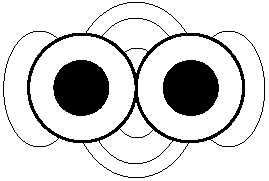
Figure D-2 depicts the electromagnetic field lines that surround the dielectric material in a twisted pair of wires.

Figure D-2. Dielectric field surrounding a pair of wires.
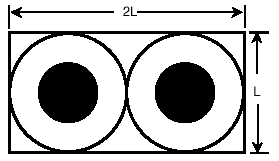
This geometry is simplified as shown in Figure D-3 by including the region that encompasses most of the electromagnetic field.

Figure D-3. Simplified geometry that includes most of the electromagnetic field surrounding a twisted pair of wires.
The following heuristic approach modifies the capacitance value given by Equation D-1 for estimating the capacitance of a twisted wire pair based on the geometry of Figure D-3. It assumes that all the electromagnetic field energy is contained in a box surrounding the two wires and their insulation. It gives a reasonable approximation to the capacitance in a closed form equation. An exact closed form solution for the capacitance is not known.
The area of the cable is given by
 |
(D-5) |
where L is the diameter of the wire, including the polyethylene insulation.
The area of the box surrounding the twisted wire pair is given as
| (D-6) |
The ratio of the cable area to the box area is thus:
 |
(D-7) |
From Equation D-3, the capacitance of the twisted wire pair becomes
| (D-8) |
For 100 ft (30 m) of wire,
| (D-9) |
Table D-1 shows that the actual measured capacitance is in the range of 997 to 1006 pF for 100 ft (30 m) of wire. All units of picofarads per foot may be converted to picofarads per meter by multiplying by 0.305 meters per foot. Thus, the heuristic calculation produces a reasonable value. The heuristic result may be fed into finite element analysis models as a first approximation to a final "exact" answer.
The internal inductance Li is calculated using Equation A-23 of Appendix A with µr =1 and µ0 =4 p x 10-7 H/m. |
µH/m can be converted to to µH/ft by dividing by 0.3048. |
The inductance L of the twisted wire pair is given by
| (D-10) |
The internal inductance Li of copper at 1 kHz is 0.05 µH/m. Thus,
| (D-11) |
For Belden 9438 wire,
| (D-12) |
or
| (D-13) |
For 100 ft (30 m) of wire,
| (D-14) |
| Frequency (kHz) | Open circuit measurement of capacitance (pF) | Open circuit measurement of conductance (µmhos) | Short circuit measurement of inductance (µH) | Short circuit measurement of resistance (Ω) |
|---|---|---|---|---|
| 0.1 | 997 | -0.0005 | 22.87 | 0.57 |
| 1.0 | 999 | -0.0082 | 22.95 | 0.57 |
| 5.0 | 1000 | -0.056 | 22.97 | 0.58 |
| 10.0 | 1001 | -0.14 | 22.91 | 0.60 |
| 15.0 | 1002 | -0.24 | 22.83 | 0.63 |
| 20.0 | 1002 | -0.36 | 22.72 | 0.67 |
| 25.0 | 1002 | -0.51 | 22.60 | 0.72 |
| 30.0 | 1002 | -0.67 | 22.47 | 0.77 |
| 35.2941 | 1003 | -0.85 | 22.33 | 0.82 |
| 40.0 | 1003 | -1.02 | 22.21 | 0.87 |
| 45.4545 | 1003 | -1.21 | 22.09 | 0.92 |
| 50.0 | 1003 | -1.40 | 21.99 | 0.97 |
| 54.5454 | 1003 | -1.58 | 21.90 | 1.01 |
| 60.0 | 1003 | -1.77 | 21.8 | 1.06 |
| 66.6666 | 1003 | -2.03 | 21.69 | 1.12 |
| 71.4286 | 1003 | -2.26 | 21.62 | 1.16 |
| 75.0 | 1004 | -2.43 | 21.57 | 1.19 |
| 80.0 | 1004 | -2.67 | 21.51 | 1.24 |
| 85.714 | 1004 | -2.95 | 21.44 | 1.28 |
| 96.0 | 1004 | -3.46 | 21.33 | 1.37 |
| 100.0 | 1005 | -3.79 | 21.29 | 1.4 |
| 120.0 | 1005 | -4.74 | 21.12 | 1.56 |
| 125.0 | 1006 | -5.02 | 21.09 | 1.59 |
| 150.0 | 1006 | -6.52 | 20.93 | 1.78 |
| Type: Twisted pair of Belden 9438 wire (not shielded) |
| Gauge: #14 AWG |
| Twists per foot: 5.5 (18.1 twists per meter) |
| Pair length: 100 ft (30 m) |
| Wire location: Laboratory floor, Turner-Fairbank Highway Research Center |
| Measuring Instrument: HP 4284A |
| Note: Balun unavailable; instrument unbalanced during measurements |
| Frequency (kHz) | Belden 8718 cable (#12 AWG) | Belden 8720 cable | ||
|---|---|---|---|---|
| Inductance (µH) | Resistance (Ω) | Inductance (µH) | Resistance (Ω) | |
| 0.1 | 19.78 | 0.35 | 21.00 | 0.59 |
| 1 | 19.96 | 0.35 | 21.14 | 0.59 |
| 5 | 19.94 | 0.37 | 21.16 | 0.60 |
| 10 | 19.78 | 0.43 | 21.07 | 0.64 |
| 15 | 19.54 | 0.51 | 20.94 | 0.71 |
| 20 | 19.26 | 0.62 | 20.76 | 0.80 |
| 25 | 18.96 | 0.74 | 20.56 | 0.91 |
| 30 | 18.65 | 0.87 | 20.33 | 1.04 |
| 35.2941 | 18.33 | 1.02 | 20.08 | 1.19 |
| 40 | 18.05 | 1.16 | 19.84 | 1.33 |
| 45.4545 | 17.74 | 1.33 | 19.57 | 1.50 |
| 50 | 17.49 | 1.47 | 19.34 | 1.64 |
| 54.5454 | 17.24 | 1.62 | 19.11 | 1.79 |
| 60 | 16.96 | 1.79 | 18.84 | 1.97 |
| 66.6666 | 16.63 | 2.00 | 18.51 | 2.20 |
| 71.4286 | 16.39 | 2.16 | 18.28 | 2.36 |
| 75 | 16.23 | 2.27 | 18.11 | 2.48 |
| 80 | 16.00 | 2.43 | 17.88 | 2.65 |
| 85.714 | 15.75 | 2.60 | 17.78 | 2.89 |
| 96 | 15.32 | 2.91 | 17.18 | 3.18 |
| 100 | 15.16 | 3.03 | 17.01 | 3.30 |
| 120 | 14.43 | 3.58 | 16.25 | 3.90 |
| 125 | 14.27 | 3.711 | 16.07 | 4.04 |
| 150 | 13.52 | 4.29 | 15.27 | 4.67 |
| Type: Shielded cable |
| Gauge: #12 or #14 AWG |
| Length: 100 ft (30 m) |
| Wire location: Laboratory floor, Turner-Fairbank Highway Research Center |
| Measuring Instrument: HP 4284A |
| Note: Balun unavailable; instrument unbalanced during measurements |
| Frequency (kHz) | Inductance (µH) | Resistance (Ω) | Quality factor (Q) |
|---|---|---|---|
| 0.1 | 94.80 | 0.53 | 0.1 |
| 1 | 94.52 | 0.53 | 1 |
| 5 | 94.08 | 0.56 | 5 |
| 10 | 93.27 | 0.63 | 9 |
| 15 | 93.37 | 0.73 | 12 |
| 20 | 92.98 | 0.86 | 14 |
| 25 | 92.59 | 1.01 | 15 |
| 30 | 92.21 | 1.16 | 15 |
| 35.2941 | 91.81 | 1.34 | 15 |
| 40 | 91.47 | 1.49 | 15 |
| 45.4545 | 91.09 | 1.68 | 16 |
| 50 | 90.79 | 1.84 | 16 |
| 54.5454 | 90.50 | 2.00 | 16 |
| 60 | 90.17 | 2.18 | 16 |
| 66.6666 | 89.79 | 2.41 | 16 |
| 71.4286 | 89.53 | 2.57 | 16 |
| 75 | 89.34 | 2.69 | 16 |
| 80 | 89.09 | 2.85 | 16 |
| 85.714 | 88.82 | 3.03 | 16 |
| 96 | 88.36 | 3.33 | 16 |
| 100 | 88.20 | 3.44 | 16 |
| 120 | 87.47 | 3.93 | 17 |
| 125 | 87.31 | 4.03 | 17 |
| 150 | 86.65 | 4.44 | 18 |
| Loop size: 6 x 6 ft (1.8 x 1.8 m) |
| Number of turns: 3 (closely wound) |
| Gauge: #14 AWG Loop location: 3 ft (0.9 m) above electronics laboratory floor, Turner-Fairbank Highway Research Center Lead-in cable: Belden 8718 (# 12 AWG) |
| Lead-In cable length: 100 ft (30 m) |
| Measuring Instrument: HP 4284A |
| Note: Balun unavailable; instrument unbalanced during measurements |
| Frequency (kHz) | Inductance (µH) | Resistance (Ω) | Quality factor (Q) |
|---|---|---|---|
| 0.1 | 96.80 | 0.77 | 0.1 |
| 1 | 95.78 | 0.77 | 0.8 |
| 5 | 95.37 | 0.79 | 4 |
| 10 | 95.10 | 0.85 | 7 |
| 15 | 94.85 | 0.94 | 10 |
| 20 | 94.59 | 1.05 | 11 |
| 25 | 94.29 | 1.18 | 13 |
| 30 | 94.00 | 1.33 | 13 |
| 35.2941 | 93.67 | 1.49 | 14 |
| 40 | 93.38 | 1.65 | 14 |
| 45.4545 | 93.04 | 1.84 | 14 |
| 50 | 92.76 | 2.00 | 15 |
| 54.5454 | 92.48 | 2.17 | 15 |
| 60 | 92.16 | 2.37 | 15 |
| 66.6666 | 91.78 | 2.60 | 15 |
| 71.4286 | 91.51 | 2.77 | 15 |
| 75 | 91.20 | 2.90 | 15 |
| 80 | 91.06 | 3.07 | 15 |
| 85.714 | 90.77 | 3.26 | 15 |
| 96 | 90.28 | 3.59 | 15 |
| 100 | 90.10 | 3.70 | 15 |
| 120 | 89.30 | 4.24 | 16 |
| 125 | 89.12 | 4.35 | 16 |
| 150 | 88.35 | 4.80 | 17 |
| Loop size: 6 x 6 ft (1.8 x 1.8 m) |
| Number of turns: 3 (closely wound) |
| Gauge: #14 AWG |
| Loop location: 3 feet (0.9 m) above electronics laboratory floor, Turner-Fairbank Highway Research Center |
| Lead-in cable: Belden 8720 (# 14 AWG) |
| Lead-in cable length: 100 ft (30 m) |
| Measuring instrument: HP 4284A |
| Note: Balun unavailable; instrument unbalanced during measurements |
| Frequency (kHz) | Inductance (µh) | Resistance (Ω) | Quality factor (Q) |
|---|---|---|---|
| 0.1 | 98.19 | 0.75 | 0.1 |
| 1 | 97.83 | 0.75 | 0.8 |
| 5 | 97.43 | 0.77 | 4 |
| 10 | 97.20 | 0.81 | 8 |
| 15 | 97.04 | 0.86 | 11 |
| 20 | 96.88 | 0.92 | 13 |
| 25 | 96.74 | 0.99 | 15 |
| 30 | 96.61 | 1.06 | 17 |
| 35.2941 | 96.50 | 1.14 | 19 |
| 40 | 96.43 | 1.21 | 20 |
| 45.4545 | 96.37 | 1.30 | 21 |
| 50 | 96.34 | 1.36 | 22 |
| 54.5454 | 96.34 | 1.43 | 23 |
| 60 | 96.36 | 1.51 | 24 |
| 66.6666 | 96.43 | 1.60 | 25 |
| 71.4286 | 96.50 | 1.67 | 26 |
| 75 | 96.56 | 1.72 | 27 |
| 80 | 96.68 | 1.78 | 27 |
| 85.714 | 96.83 | 1.86 | 28 |
| 96 | 97.18 | 2.00 | 29 |
| 100 | 97.34 | 2.05 | 30 |
| 120 | 98.34 | 2.31 | 32 |
| 125 | 98.63 | 2.38 | 33 |
| 150 | 100.42 | 2.7 | 35 |
| Loop size: 6 x 6 ft (1.8 x 1.8 m) |
| Number of turns: 3 (closely wound) |
| Gauge: #14 AWG |
| Loop location: 3 ft (0.9 m) above electronics laboratory floor, Turner-Fairbank Highway Research Center |
| Lead-in cable: Belden 9438 twisted-pair (5.5 twists/ft) (15/m) |
| Lead-in cable length: 100 ft (30 m) |
| Measuring instrument: HP 4284A |
| Note: Balun unavailable; instrument unbalanced during measurements |
| Frequency (kHz) | Inductance (µH) | Resistance (Ω) | Quality factor (Q) |
|---|---|---|---|
| 0.1 | 75.02 | 0.18 | 0.3 |
| 1 | 74.33 | 0.19 | 3 |
| 5 | 74.35 | 0.20 | 12 |
| 10 | 74.15 | 0.21 | 22 |
| 15 | 74.04 | 0.23 | 30 |
| 20 | 73.95 | 0.25 | 37 |
| 25 | 73.86 | 0.28 | 42 |
| 30 | 73.79 | 0.30 | 46 |
| 35.2941 | 73.71 | 0.33 | 50 |
| 40 | 73.66 | 0.36 | 52 |
| 45.4545 | 73.61 | 0.39 | 55 |
| 50 | 73.57 | 0.41 | 57 |
| 54.5454 | 73.53 | 0.43 | 59 |
| 60 | 73.48 | 0.46 | 61 |
| 66.6666 | 73.44 | 0.49 | 63 |
| 71.4286 | 73.41 | 0.51 | 64 |
| 75 | 73.39 | 0.53 | 65 |
| 80 | 73.36 | 0.55 | 67 |
| 85.714 | 73.34 | 0.58 | 68 |
| 96 | 73.30 | 0.62 | 71 |
| 100 | 73.29 | 0.64 | 72 |
| 120 | 73.25 | 0.73 | 76 |
| 125 | 73.25 | 0.75 | 77 |
| 150 | 73.25 | 0.84 | 82 |
| Loop size: 6 x 6 ft (1.8 x 1.8 m) |
| Number of turns: 3 (closely wound) |
| Gauge: #14 AWG |
| Loop location: 3 ft (0.9 m) above electronics laboratory floor, Turner-Fairbank Highway Research Center |
| Lead-in cable: None |
| Lead-in Length: 0 ft (0 m) |
| Measuring instrument: HP 4284A |
| Note: Balun unavailable; instrument unbalanced during measurements |
Previous | Table of Contents | Next
FHWA-HRT-06-139 |