U.S. Department of Transportation
Federal Highway Administration
1200 New Jersey Avenue, SE
Washington, DC 20590
202-366-4000


Skip to content
Facebook iconYouTube iconTwitter iconFlickr iconLinkedInInstagram

Federal Highway Administration Research and Technology
Coordinating, Developing, and Delivering Highway Transportation Innovations

Report
This report is an archived publication and may contain dated technical, contact, and link information
Publication Number: FHWA-HRT-06-139
Date: October 2006

Traffic Detector Handbook:Third Edition—Volume II

APPENDIX E. VEHICLE DETECTION SENSITIVITY FORMULAS FOR RECTANGULAR LOOPS

ABSTRACT

This appendix describes the derivation and application of formulas to calculate the vehicle detection sensitivity of single-turn and multiturn rectangular loops of coaxial wire. The effect on detection sensitivity of reinforcing steel mesh in the pavement and lead-in cable inductance is accounted for in the models. The loop is installed in the roadway pavement and connected to a roadside electronics unit by lead-in cable, which is modeled as a transmission line. When a vehicle passes over the loop, eddy currents induced in the vehicle undercarriage cause a decrease in loop inductance, which is sensed by the electronics unit.

The multiturn rectangular loop is modeled as a number of series connected, single-turn, rectangular loops that exhibit mutual coupling between each turn of wire. The multiturn loop is represented by the primary of an air core transformer, which contains two secondary windings composed of shorted turns that simulate the vehicle undercarriage and reinforcing steel mesh. The derived equations are used to calculate tables of vehicle detection sensitivity, expressed as vehicle undercarriage detection height, as a function of number of loop turns, loop size, and loop spacing.

INTRODUCTION

The inductive-loop detector (ILD) system is used nationwide to detect stopped or moving vehicles for traffic surveillance and control systems. A typical ILD system consists of a 3-turn, 6- x 6-ft (1.83- x 1.83-m) loop of #14 AWG wire embedded in the pavement, a lead-in cable to roadside, and roadside electronics unit. The vehicle-detection sensitivity is the normalized inductance change at the terminals of the electronics unit when a vehicle is sensed by the loop. High-ground-clearance vehicles such as trucks cause a small change in loop inductance, which sometimes results in nondetection of part of the vehicle. Increasing the sensitivity of the electronics unit to sense such small inductance changes usually increases the response time of the electronics unit, which causes errors in ILD applications for measuring vehicle speed.

The vehicle-detection sensitivity of an inductive-loop detection system is maximized when the spacing between loop turns is correctly selected. The increased sensitivity should improve detection of high-ground-clearance trucks.

This appendix is based on a previous paper that developed a detectionsensitivity formula for a single-turn rectangular loop.(1) It was shown that, with no reinforcing steel, the sensitivity is proportional to the mutual inductance squared, divided by the product of the self-inductance of the single-turn loop and the self-inductance of the shorted-turn loop simulating the vehicle. If the loop turns of a multiturn, rectangular loop are tightly coupled, the sensitivity is independent of the number of loop turns, provided the loop inductance is approximately ten times larger than the inductance of the lead-in cable. A formula for the self-inductance of a multiturn rectangular loop, which accounts for leakage flux, was developed in a second paper.(2) As the loop turns become more widely spaced, the increased leakage flux causes the loop self-inductance to decrease, which results in increased detection sensitivity until the decrease in mutual coupling to the shorted turn becomes significant.

VEHICLE-DETECTION SENSITIVITY THEORY

VEHICLE MODEL

The vehicle is modeled as a flat, perfectly conducting plate at a height above the loop approximately equal to the average undercarriage height of the vehicle. The width and length of the plate are equal to the width and length of the vehicle. The continuous, perfectly conducting plate can be simulated by a wire grid, provided the mesh elements are sufficiently small.

In order to simplify the calculations of loop system sensitivity, the wire grid simulating the vehicle is set equal to the size of the inductive loop in the roadway. When the wire grid is coaxially located over the loop, the interior currents induced in the grid by the loop cancel, leaving a current flowing around the perimeter of the grid, provided the grid width and length are equal to those of the loop. Thus, the grid can be replaced with a wire loop or shorted turn equal to the grid perimeter. This case represents a vehicle centered over the loop (i.e., maximum percentage inductance change of the loop). Magnetic effects on the loop due to the permeable material of the vehicle are assumed to be negligible.

REINFORCING STEEL MODEL

The mesh elements of the reinforcing steel in the pavement are considered sufficiently small and the size of the mesh sufficiently large compared to the loop so that the steel mesh can be replaced with a perfectly conducting plane of infinite extent. Based on image theory, the infinitely conducting plane is replaced with an image loop at twice the distance from the loop to the reinforcing steel. Figure E-1 illustrates the geometry of the vehicle and reinforcing steel shorted turn model for a two-turn rectangular inductive loop. The direction of induced currents determines the sign of the mutual inductance terms used in the circuit model. A plus sign indicates current flow in the same direction and a minus sign current flow in opposite directions.
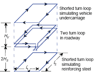
Figure E-1 models the vehicle and reinforcing steel as rectangular shorted turns of the same size, and above and below, a square two-turn rectangular inductive loop. A shorted turn rectangular loop simulates the effects of a vehicle undercarriage at a height of Capital H sub V on the loop. Similarly, a second shorted turn rectangular loop at a depth of two times Capital H sub S simulates the effects of reinforcing steel rebars in the pavement. The direction of induced currents determines the sign of the mutual inductance terms used in the following circuit model. The lengths of the sides of the loops are represented by the terms italic small L sub 1 and italic small L sub 2.

Figure E-1. Two-turn loop in roadway.

CIRCUIT MODEL FOR ONE-TURN LOOP

Figure E-2 shows the air core transformer model of a one-turn inductive loop, vehicle undercarriage, and reinforcing steel mesh. The inductive loop is modeled as the primary winding of the transformer, while the vehicle and reinforcing steel are modeled as shorted turn secondary windings. The secondary winding simulating the vehicle is movable to simulate changes in vehicle undercarriage height HV. The secondary winding modeling the shorted turn reinforcing steel mesh is located at a distance of twice the steel mesh to inductive loop spacing HS.
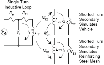
Figure E-2 illustrates the conversion of the electrical models of Figure E-1 into circuit diagrams. The larger circuit represents the inductive loop. The two smaller circuits simulate the vehicle and the reinforcing steel. The vehicle circuit has a resistance of R sub 22 and a current of I sub 2 while the reinforcing steel circuit has a resistance of R sub 33 and a current of I sub 3. There is an inductance of L sub 11 in the main circuit and of L sub 22 and L sub 33 in the vehicle and reinforcing steel circuits respectively.

Figure E-2. Single-turn inductive-loop circuit model.

Circuit Equations for One-Turn Loop

The circuit equations corresponding to Figure E-2 are:

Z is impedance in ohms. I is current in amperes.Equations E-2 and E-3 are set equal to 0 since there is no external driving voltage in the two secondary windings in Figure E-2 that contain L22 and L33.

Equation E-1. Capital V subscript 1 is equal to the sum of the product of Capital Z subscript 11 multiplied by Capital I subscript 1, added to the product of Capital Z subscript 12 multiplied by Capital I subscript 2, added to the product of Capital Z subscript 12 multiplied by Capital I subscript 3. (E-1)
Equation E-2. Capital O is equal to the sum of the product of Capital Z subscript 21 multiplied by Capital I subscript 1, added to the product of Capital Z subscript 22 multiplied by capital I subscript 2, added to the product of Capital Z subscript 23 multiplied by capital I subscript 3. (E-2)
Equation E-3. Capital O is equal to the sum of the product of Capital Z subscript 31 multiplied by Capital I subscript 1, added to the product of Capital Z subscript 32 multiplied by capital I subscript 2, added to the product of Capital Z subscript 33 multiplied by capital I subscript 3. (E-3)
 

where

Equation E-4. Capital Z subscript 11 is equal to the sum of Capital R subscript 11 added to the product of lowercase j multiplied by omega multiplied by Capital L subscript 11. (E-4)
Equation E-5. Capital Z subscript 22 is equal to the sum of Capital R subscript 22 added to the product of lowercase j multiplied by omega multiplied by Capital L subscript 22. (E-5)
Equation E-6. Capital Z subscript 33 is equal to the sum of Capital R subscript 33 added to the product of lowercase j multiplied by omega multiplied by Capital L subscript 33. (E-6)
Equation E-7. Capital Z subscript 12 is equal to the product of lowercase j multiplied by omega multiplied by Capital M subscript 12. (E-7)
Equation E-8. Capital Z subscript 13 is equal to the product of lowercase j multiplied by omega multiplied by Capital M subscript 13. (E-8)

R is resistance in ohms. j represents the square root of -1 in the imaginary term. ω is frequency in radians. L is inductance in henries.

All mutual impedances are symmetrical (i.e., Z12 = Z21, Z13 = Z31, Z23 = Z32).

Experimental measurements show that the quality factor ωL11 /R11 of the loop driving point impedance Z11 is ≥ 10.

Assuming small circuit loss to simplify calculations gives

Equation E-9. Capital Z subscript 11 is equal to the product of lowercase j multiplied by omega multiplied by Capital L subscript 11. (E-9)
Equation E-10. Capital Z subscript 22 is equal to the product of lowercase j multiplied by omega multiplied by Capital L subscript 22. (E-10)
Equation E-11. Capital Z subscript 33 is equal to the product of lowercase j multiplied by omega multiplied by Capital L subscript 33. (E-11)
Inductive-Loop Driving-Point Impedance

The loop driving-point impedance Z1 from Equations E-1, E-2, and E-3 is

Equation E-12. Capital Z subscript 1 is equal to the quotient of Capital V subscript 1 divided by Capital I subscript 1, which in turn is equal to the following quotient. The numerator is equal to the difference of the product of Capital Z subscript 11 multiplied by Capital Z subscript 22 multiplied by Capital Z subscript 33, minus the product of Capital Z subscript 31 squared multiplied by Capital Z subscript 22, minus the product of Capital Z subscript 32 squared multiplied by Capital Z subscript 11, minus the product of Capital Z subscript 21 squared multiplied by Capital Z subscript 33, added to the product of 2 multiplied by Capital Z subscript 21 multiplied by Capital Z subscript 31 multiplied by Capital Z subscript 32. The denominator is equal to the difference of the product of Capital Z subscript 22 multiplied by Capital Z subscript 33 minus Capital Z subscript 32 squared. (E-12)

If the reinforcing mesh is spaced a great distance from the inductive loop,

Then

Equation E-13. Capital Z subscript 1 is equal to the quotient of the difference of the product of Capital Z subscript 11 multiplied by Capital Z subscript 22 minus Capital Z subscript 21 squared, all divided by Capital Z subscript 22. (E-13)

In this case, the loop driving-point impedance Z1 depends only on the effect of the vehicle.

Inductive-Loop Sensitivity

The sensitivity SL of an inductive loop is defined as

NV represents the value of the variable when no vehicle is present.V represents the value of the variable when a vehicle is present.

Equation E-14. Capital S subscript Capital L is equal to the quotient of Delta Capital Z subscript 1 divided by Capital Z subscript 1 superscript capital N capital V. (E-14)

The change in loop driving-point impedance ΔZ1 is given by

Equation E-15. Delta Capital Z subscript 1 is equal to the difference between Capital Z subscript 1 superscript capital N capital V, minus Capital Z subscript 1 superscript capital V. (E-15)

where ΔZ1NV is the loop driving-point impedance with no vehicle present and ΔZ1V is the loop driving-point impedance when sensing a vehicle.

The loop driving-point impedance Z1 can also be expressed as

Equation E-16. Capital Z subscript 1 is equal to Capital Z subscript 11 minus the following quotient. The numerator is equal to the sum of the product of Capital Z subscript 13 squared multiplied by Capital Z subscript 22, added to the product of Capital Z subscript 12 squared multiplied by Capital Z subscript 33, minus the product of 2 multiplied by Capital Z subscript 12 multiplied by Capital Z subscript 13 multiplied by Capital Z subscript 23. The denominator is equal to the difference of the product of Capital Z subscript 22 multiplied by Capital Z subscript 33 minus Capital Z subscript 23 squared. (E-16)

Then, if no vehicle is present,

Equation E-17. Capital Z subscript 1 superscript capital N capital V is equal to Capital Z subscript 11 minus the quotient of Capital Z subscript 13 squared divided by Capital Z subscript 33. This in turn is equal to the quotient of the difference of the product of Capital Z subscript 11 multiplied by Capital Z subscript 33 minus Capital Z subscript 13 squared all divided by Capital Z subscript 33. (E-17)
Equation E-18. Capital Z subscript 1 superscript capital V is equal to Capital Z subscript 11 minus the following quotient. The numerator is equal to the sum of the product of Capital Z subscript 13 squared multiplied by Capital Z subscript 22, added to the product of Capital Z subscript 12 squared multiplied by Capital Z subscript 33, minus the product of 2 multiplied by Capital Z subscript 12 multiplied by Capital Z subscript 13 multiplied by Capital Z subscript 33 multiplied by Capital Z subscript 23. The denominator is equal to the difference of the product of Capital Z subscript 22 multiplied by Capital Z subscript 33, minus Capital Z subscript 23 squared. (E-18)
Equation E-19. Delta Capital Z subscript 1 is equal to the following quotient. The numerator is equal to the sum of the product of Capital Z subscript 13 squared multiplied by Capital Z subscript 23 squared, added to the product of Capital Z subscript 12 squared multiplied by Capital Z subscript 33 squared, minus the product of 2 multiplied by Capital Z subscript 12 multiplied by Capital Z subscript 13 multiplied by Capital Z subscript 33 multiplied by Capital Z subscript 23. The denominator is equal to the product of the sum of the product of Capital Z subscript 22 multiplied by Capital Z subscript 33, minus Capital Z subscript 23 squared, all multiplied by Capital Z subscript 33. (E-19)

The loop sensitivity SL is given by

Equation E-20. Capital S subscript Capital L is equal to the quotient of Delta Capital Z subscript 1 divided by Capital Z subscript 1 superscript capital N capital V, which is also equal to the following quotient. The numerator is equal to the sum of the product of Capital Z subscript 13 squared multiplied by Capital Z subscript 23 squared added to the product of Capital Z subscript 12 squared multiplied by Capital Z subscript 33 squared minus the product of 2 multiplied by Capital Z subscript 12 multiplied by Capital Z subscript 13 multiplied by Capital Z subscript 33 multiplied by Capital Z subscript 23. The denominator is equal to the product of the difference of the product of Capital Z subscript 11 multiplied by Capital Z subscript 33 minus the square of Capital Z sub 13, multiplied by the product of Capital Z subscript 22 multiplied by Capital Z subscript 33 minus Capital Z subscript 23 squared. (E-20)

if

Equation E-21. Capital S subscript Capital L is equal to the quotient of the square of Capital Z subscript 12 divided by the product of Capital Z subscript 11 multiplied by Capital Z subscript 22. (E-21)

Applying Equations E-9, E-10, and E-11 to Equation E-20 yields the loop sensitivity SL in percent as

Equation E-22. Capital S subscript Capital L is equal to 100 multiplied by the following quotient. The numerator is equal to the sum of the product of Capital M subscript 12 squared multiplied by Capital L subscript 33 squared, added to the product of Capital M subscript 13 squared multiplied by Capital L subscript 23 squared minus the product of 2 multiplied by Capital M subscript 12 multiplied by Capital M subscript 13 multiplied by Capital M subscript 23 multiplied by Capital L subscript 33. The denominator is equal to the product of the difference of the product of Capital L subscript 11 multiplied by Capital L subscript 33 minus Capital M subscript 13 squared minus Capital M subscript 13 squared, multiplied by the difference of the product of Capital L subscript 22 multiplied by Capital L subscript 33 minus Capital M subscript 23 squared. (E-22)
where  
 SL = inductive loop sensitivity (percent)
 M12 = mutual inductance between inductive loop and loop-simulating vehicle (H)
 M13 = mutual inductance between inductive loop and loop-simulating reinforcing mesh (H)
 M23 = mutual inductance between loop-simulating vehicle and loop-simulating reinforcing mesh (H)
 L11 = self-inductance of inductive loop (H)
 L22 = self-inductance of loop-simulating vehicle (H)
 L33 = self-inductance of loop-simulating reinforcing steel mesh (H).

When reinforcing steel mesh is not present,

Equation E-23. Capital S subscript capital L is equal to 100 multiplied by the quotient of the square of Capital M subscript 12, divided by the product of Capital L subscript 11 multiplied by Capital L subscript 22. (E-23)

CIRCUIT MODEL FOR TWO-TURN LOOP

Figure E-3 shows the air core transformer model of a two-turn inductive loop, vehicle undercarriage, and reinforcing steel mesh. Mutual inductance terms that model the effects of the multiple-turn loop have been added to the model.
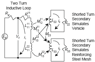
Figure E-3 illustrates the conversion of the electrical models of Figure E-1 into circuit diagrams. The larger circuit represents the inductive loop with two turns of wire rather than one. Each turn of wire interacts with both the shorted turn of vehicle circuit and the shorted turn of the reinforcing steel mesh in the roadway circuit. These two smaller circuits simulate the vehicle and the reinforcing steel. The vehicle circuit has a resistance of R sub 22 and a current of I sub 2 while the reinforcing steel circuit has a resistance of R sub 33 and a current of I sub 3. There is an inductance of L sub 11 in the main circuit and of L sub 22 and L sub 33 in the vehicle and reinforcing steel circuits respectively. These create interactions between the simulated vehicle of M sub 12 super 11 with the first turn of loop wire and of M sub 13 super 22 with the second turn of loop wire. Similarly, there are interactions between the simulated reinforcing steel of M sub 13 super 11 with the first turn of loop wire and of M sub 13 super 22 with the second turn of loop wire.

Figure E-3. Two-turn inductive-loop circuit model.

Circuit Equations for Two-Turn Loop

From Figure E-3, the circuit equations for the two-turn loop are given by

Equation E-24. Capital V subscript 1 is equal to the sum of the following three products. The first product is the sum of Capital Z subscript 11 superscript 11 added to capital Z subscript 11 superscript 22 added to Capital Z subscript 11 superscript 12 added to Capital Z subscript 11 superscript 21, all multiplied by capital I subscript 1. The second product is the sum of Capital Z subscript 12 superscript 11 added to Capital Z subscript 12 superscript 22, all multiplied by capital I subscript 2. The third product is the sum of Capital Z subscript 13 superscript 11 added to Capital Z subscript 13 superscript 22, all multiplied by Capital I subscript 3. (E-24)
Equation E-25. Zero is equal to the sum of the product of the sum of Capital Z subscript 21 superscript 11 added to Capital Z subscript 21 superscript 22 all multiplied by Capital I subscript 1, added to the product of Capital Z subscript 22 superscript 22 multiplied by Capital I subscript 2, added to the product of Capital Z subscript 23 superscript 22 multiplied by Capital I subscript 3. (E-25)
Equation E-26. Zero is equal to the sum of the product of the sum of Capital Z subscript 31 superscript 11 added to Capital Z subscript 31 superscript 22, all multiplied by Capital I subscript 1, added to the product of Capital Z subscript 32 superscript 22 multiplied by Capital I subscript 2, added to the product of Capital Z subscript 33 superscript 33 multiplied by Capital I subscript 3. (E-26)
where 
 Z1211 = mutual impedance between primary turn 1 of the transformer and secondary shorted turn 2, which models the vehicle,
 Z1222 = mutual impedance between primary turn 2 of the transformer and secondary shorted turn 2, which models the vehicle,
 Z1112 = mutual impedance between primary turn 1 and primary turn 2.

Then

Equation E-27. Capital Z subscript 11 is equal to the sum of Capital Z subscript 11 superscript 11 added to Capital Z subscript 11 superscript 22 added to Capital Z subscript 11 superscript 12 added to Capital Z subscript 11 superscript 21. (E-27)
Equation E-28. Capital Z subscript 12 is equal to the sum of Capital Z subscript 12 superscript 11 added to Capital Z subscript 12 superscript 22. (E-28)
Equation E-29. Capital Z subscript 13 is equal to the sum of Capital Z subscript 13 superscript 11 added to Capital Z subscript 13 superscript 22 (E-29)
Equation E-30. Capital Z subscript 21 is equal to the sum of Capital Z subscript 21 superscript 11 added to Capital Z subscript 21 superscript 22 (E-30)
Equation E-31. Capital Z subscript 22 is equal to Capital Z subscript 22 superscript 22. (E-31)
Equation E-32. Capital Z subscript 23 is equal to Capital Z subscript 23 superscript 22. (E-32)
Equation E-33. Capital Z subscript 31 is equal to the sum of Capital Z subscript 31 superscript 11 added to Capital Z subscript 31 superscript 22. (E-33)
Equation E-34. Capital Z subscript 32 is equal to Capital Z subscript 32 superscript 22. (E-34)
Equation E-35.Capital Z subscript 33 is equal to Capital Z subscript 33 superscript 33. (E-35)

As compared to the one-turn loop model, the self-impedance Z11 is replaced by the total two-turn loop impedance. Each mutual impedance is replaced by the sum of the mutual impedances from each turn.

CIRCUIT EQUATIONS FOR MULTITURN LOOP

Circuit equations for a multiturn loop are given by

Equation E-36. Capital V subscript 1 is equal to the sum of the product of Capital Z multiplied by Capital I subscript 1 added to the following two products. The first product is small delta subscript capital I capital J multiplied by Summation from capital I is equal to 1 to Capital N of Summation from capital J is equal to 1 to Capital N of Capital Z subscript 12 superscript capital I capital J multiplied by Capital I subscript 2. The second product is small delta subscript capital I capital J multiplied by Summation from capital I is equal to 1 to Capital N of Summation from capital J is equal to 1 to Capital N of Capital Z subscript 13 superscript capital I capital J multiplied by Capital I subscript 3. (E-36)
Equation E-37. Zero is equal to the sum of the product of small delta subscript capital I capital J multiplied by Summation from capital I is equal to 1 to Capital N of Summation from capital J is equal to 1 to Capital N of Capital Z subscript 21 superscript capital I capital J multiplied by Capital I subscript 1 added to the product of Capital Z subscript 22 multiplied by Capital I subscript 2 added to the product of Capital Z subscript 23 multiplied by Capital I subscript 3. (E-37)
Equation E-38. Zero is equal to the sum of the product of small delta subscript capital I capital J multiplied by Summation from capital I is equal to 1 to Capital N of Summation from capital J is equal to 1 to Capital N of Capital Z subscript 31 superscript capital I capital J multiplied by Capital I subscript 1 added to the product of Capital Z subscript 32 multiplied by Capital I subscript 2 added to the product of Capital Z subscript 33 multiplied by Capital I subscript 3. (E-38)

where δij is the Kronecker Delta function (i.e., δij = 1 for i = j and δij = 0 for i not equal to j). Then

Equation E-39. Capital Z subscript 11 is equal to Capital Z subscript Capital N is equal to multiturn loop self impedance. (E-39)
Equation E-40. Capital Z subscript 12 is equal to the product of delta subscript capital I capital J multiplied by Summation from capital I is equal to 1 to Capital N of Summation from capital J is equal to 1 to Capital N of Capital Z subscript 12 superscript capital I capital J. (E-40)
Equation E-41. Capital Z subscript 13 is equal to the product of delta subscript capital I capital J multiplied by Summation from capital I is equal to 1 to Capital N of Summation from capital J is equal to 1 to Capital N of Capital Z subscript 13 superscript capital I capital J. (E-41)
Equation E-42. Capital Z subscript 21 is equal to the product of delta subscript capital I capital J multiplied by Summation from capital I is equal to 1 to Capital N of Summation from capital J is equal to 1 to Capital N of Capital Z subscript 21 superscript capital I capital J. (E-42)
Equation E-43. Capital Z subscript 31 is equal to the product of delta subscript capital I capital J multiplied by Summation from capital I is equal to 1 to Capital N of Summation from capital J is equal to 1 to Capital N of Capital Z subscript 31 superscript capital I capital J (E-43)

Equations E-39–E-43 are generalized for the multiturn case by letting

Equation E-44. Capital L subscript 11 is equal to Capital L subscript N superscript star. (E-44)
Equation E-45. Capital M subscript 12 is equal to the product of delta subscript capital I capital J multiplied by Summation from capital I is equal to 1 to Capital N of Summation from capital J is equal to 1 to Capital N of Capital M subscript 12 superscript capital I capital J. (E-45)
Equation E-46. Capital M subscript 13 is equal to the product of delta subscript capital I capital J multiplied by Summation from capital I is equal to 1 to Capital N of Summation from capital J is equal to 1 to Capital N of Capital Z subscript 13 superscript capital I capital J. (E-46)

where L*N is the total self-inductance of the loop.

VEHICLE-DETECTION SENSITIVITY FOR A MULTITURN LOOP

Detection sensitivity is expressed as

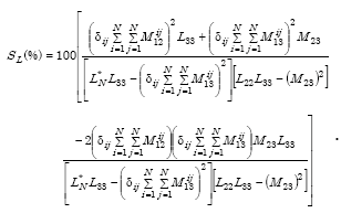
Equation E-47. Capital S subscript capital L expressed as a percentage is equal to 100 multiplied by the following quotient. The numerator is equal to 3 products summed together. The first product is the value of the product of delta subscript capital I capital J multiplied by Summation from capital I is equal to 1 to Capital N of Summation from capital J is equal to 1 to Capital N of Capital M subscript 12 superscript capital I capital J, all squared, multiplied by capital L subscript 33. The second product is the value of the product of delta subscript capital I capital J multiplied by Summation from capital I is equal to 1 to Capital N of Summation from capital J is equal to 1 to Capital N of Capital M subscript 13 superscript capital I capital J, all squared, multiplied by capital M subscript 23. The third product is negative 2 multiplied by the value of the product of delta subscript capital I capital J multiplied by Summation from capital I is equal to 1 to Capital N of Summation from capital J is equal to 1 to Capital N of Capital M subscript 12 superscript capital I capital J, multiplied by the value of the product of delta subscript capital I capital J multiplied by Summation from capital I is equal to 1 to Capital N of Summation from capital J is equal to 1 to Capital N of Capital M subscript 13 superscript capital I capital J, multiplied by capital M subscript 23, multiplied by capital L subscript 33. The denominator is the product of 2 equations. The first equation is the difference between the product of capital L subscript capital N superscript star multiplied by capital L subscript 33, minus the square of the product of delta subscript capital I capital J multiplied by Summation from capital I is equal to 1 to Capital N of Summation from capital J is equal to 1 to Capital N of Capital M subscript 13 superscript capital I capital J. The second equation is the difference between the product of capital L subscript 22 multiplied by capital L subscript 33, minus the square of capital M subscript 23. (E-47)

For a two-turn (N = 2) loop,

Equation E-48. Capital S subscript capital L expressed as a percentage is equal to 100 multiplied by the following quotient.The numerator is made up of 3 summations. The first summation is the product of the squared sum of Capital M subscript 12 superscript 11 added to Capital M subscript 12 superscript 22, multiplied by capital L subscript 33. The second summation is the product of the squared sum of Capital M subscript 13 superscript 11 added to Capital M subscript 13 superscript 22, multiplied by capital M subscript 23. The third summation is the product of the sum of the product of negative 2 multiplied by the sum of Capital M subscript 12 superscript 11 added to Capital M subscript 12 superscript 22, multiplied by the sum of Capital M subscript 13 superscript 11 added to Capital M subscript 13 superscript 22, multiplied by Capital M subscript 23 multiplied by Capital L subscript 33. The denominator is made up of the product of 2 equations. The first equation is the difference of the product of Capital L subscript N superscript star multiplied by Capital L subscript 33, minus the square of the sum of Capital M subscript 13 superscript 11 added to Capital M subscript 13 superscript 22. The second equation is the difference of the product between Capital L subscript 22 multiplied by Capital L subscript 33, minus the square of Capital M subscript 23. (E-48)

The formula for multiturn loop-sensitivity can be applied to any loop geometry, provided the vehicle and reinforcing steel mesh can be modeled as shorted turns.

When no reinforcing steel mesh is present, the sensitivity of the electronics unit to a change in loop-system inductance caused by vehicle passage or presence is given by

Equation E-49. Capital S subscript L calculated as a percent is equal to 100 multiplied by the following quotient. The numerator is equal to the square of the product of delta subscript capital I capital J multiplied by Summation from capital I is equal to 1 to Capital N of Summation from capital J is equal to 1 to Capital N of Capital M subscript 12 superscript capital I capital J. The denominator is equal to the product of Capital L subscript N superscript star multiplied by Capital L subscript 22. (E-49)

Equation E-47 can be applied to a multiturn rectangular loop with N coaxial, equal-spaced, identical turns. The low-frequency inductance LN for such a loop is given by(3)

Equation E-50. Capital L subscript Capital N is equal to the sum of the product of Capital N multiplied by Capital L subscript 11 added to the product of 2 multiplied by the value of Capital N minus 1 multiplied by Capital M subscript 12 added to the product of 2 multiplied by the value of Capital N minus 2 multiplied by Capital M subscript 13 added to, a continuation of the function. (E-50)

or

Equation E-51. Capital L subscript Capital N is equal to the sum of the product of Capital N multiplied by Capital L subscript 11 added to the product of 2 multiplied by the Summation from capital I is equal to 1 to Capital N of the value of capital N minus capital I, multiplied by capital M subscript equal to 1 comma capital I added to 1. (E-51)

where L11 is the self-inductance of a single turn and M1,i+1 is the mutual inductance between turn one and the i + 1 turn. This formula assumes that the smallest dimension of a loop turn length or width is much greater than the largest spacing between loop turns.

For a two-turn loop,

Equation E-52. Capital L subscript Capital N is equal to the sum of the product of 2 multiplied by Capital L subscript 11 added to the product of 2 multiplied by Capital M subscript 12. (E-52)

The total self-inductance L*N of the loop is equal to the sum of the low–frequency inductance LN and the high-frequency, skin-effect inductance LH and is expressed as

Equation E-53. Capital L subscript Capital N superscript star is equal to the sum of Capital L subscript capital N added to Capital L subscript Capital H. (E-53)

where

Equation E-54. Capital L subscript Capital H is equal to the product of 2 multiplied by the sum of the value of zeta subscript 1 added to zeta subscript 2, multiplied by Capital L superscript capital I. (E-54)

l1 and l2 are turn width (m) and turn length (m), respectively, and the internal inductance Li is 0.036 µH/m (0.111 µH/ft) at 47 kHz.

INDUCTIVE-LOOP DETECTOR SENSITIVITY

The series inductance LC of the transmission line connecting the loop in the roadway to the electronics unit reduces the inductive-loop system sensitivity SL at the electronics unit to
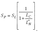
Equation E-55. Capital S subscript Capital P is equal to Capital S subscript Capital L multiplied by the following quotient. The numerator is equal to 1. The denominator is equal to 1 added to the quotient of Capital L subscript Capital C divided by Capital L subscript Capital N superscript star. (E-55)

LOOP-DETECTOR SENSITIVITY MEASURED DATA AND CALCULATED RESULTS

LOOP-DETECTOR SENSITIVITY COMPUTER PROGRAM

Equations E-47, E-51, E-53, and E-55 were programmed in BASIC and run on an IBM computer. The main program calls a subroutine, which calculates the sum of the mutual inductance from each loop turn to the image loop simulating the vehicle and image loop simulating the reinforcing steel. The main program also calls a subroutine, which calculates the external, or low-frequency inductance of a coaxial, multiturn, rectangular loop of round wire. This low-frequency inductance subroutine calls a subroutine, which calculates the mutual inductance between two coaxial, single-turn, rectangular loops. The single-turn, mutual inductance subroutine calls a subroutine, which calculates the mutual inductance between two parallel current elements.

MEASURED LOOP-DETECTOR SENSITIVITY DATA

The only known measured loop-detector sensitivity data(4) versus number of loop conductor turns are presented in Table E-1. These data were obtained by driving a compact automobile over a 6- x 6-ft (1.83- x 1.83-m) loop with 10 ft (3.05 m) of #14 underground feeder (UF) cable connected between the loop and the laboratory equipment. Loop sensitivity as a function of the number of loop turns was calculated from the change in loop inductance recorded with and without the vehicle. The sensitivity magnitude increased approximately 5 percent when the operating frequency changed from 15 to 100 kHz for four or more loop turns.

COMPARISON BETWEEN MEASURED AND CALCULATED SENSITIVITY DATA

Since the average undercarriage height of the compact automobile used was unknown, the automobile was modeled with a 6- x 6-ft (1.83- x 1.83-m) shorted turn coaxially located 0.71 ft (216 mm) over the loop of #14 AWG wire. A loop-wire spacing of 150 mils (38 mm) and lead-in cable inductance of 0.22 µH/ft (0.72 µH/m) were assumed.

Table E-1 shows that the agreement between measured and calculated loopdetector sensitivity is good. Therefore, values calculated from the computer program model can be used to infer the effects of inductive-loop design parameters on loop sensitivity as described below.

Table E-1. Comparison of measured and calculated loop detector sensitivity data.
Loop turnsMeasured loop detector
sensitivity**
(%)
Calculated loop detector
sensitivity
(%)
Difference
(%)
1 3.25 3.72 14.47
2 4.75 4.75 0
3* 5.20 5.20 0
4 5.50 5.47 -0.55
5 5.60 5.68 1.43
6 5.65 5.83 3.19
8 5.75 6.07 5.57
10 6.05 6.25 3.31
*The height of 0.71 ft (0.22 m) was selected so that the difference equaled zero.
**Data measured at f = 50 kHz.

EFFECT OF LOOP TURNS ON SENSITIVITY

Vehicle-detection height slowly increases when the turn spacing exceeds 1 inch (25 mm).

A survey by Dorsey(5) found that 15 of 21 States cut loop slots greater than 2 inches (50.8 mm) in the pavement. The spacing between the center of the conductor of the top loop turn and the center of the conductor of the bottom loop turn was assumed to be 2 inches (50.8 mm) for analysis. In practice, a much closer top-to-bottom turn spacing is used. A loop slot depth of 1-3/8 inches (35 mm) is recommended in the Traffic Detector Handbook for a two-turn loop. A nominal sensitivity of 0.098 percent was assumed for the detection threshold.

A lead-in cable length of zero was used so that the effect of loop turns on sensitivity would be independent of lead-in cable length.

The effect of the reinforcing steel mesh was removed by spacing the mesh 1000 ft (304.8 m) from the loop. Results from the loop-detector system sensitivity computer program are presented in Table E-2 for 1 to 8 loop turns. The vehicle undercarriage detection height is approximately proportional to the volume enclosed by the loop conductors and is approximately independent of the number of loop turns for a given volume. For example, the volume of the 6- × 6-ft (1.83- × 1.83-m) by 2000-mils (50.8-mm) loop is 6 ft3 (0.171 m3), as illustrated by the results in Table E-2.

EFFECT OF LOOP VOLUME ON SENSITIVITY

Vehicle-detection height slowly increases when the turn spacing exceeds 1 inch (25 mm).

Since Table E-2 demonstrates that the undercarriage detection height is approximately independent of the number of loop turns for three or more turns, the effect on loop sensitivity and hence detection height of increasing the spacing between turns in a three-turn loop was calculated as shown in Table E-3. The vehicle undercarriage detection height slowly increases when the turn spacing exceeds 1 inch (25 mm). The volume of the 6- × 6-ft (1.83- × 1.83-m) by 300-mils (7.6-mm) loop is 0.90 ft3 (0.25 mm3) with a detection height of 4.7 ft (1.43 m). Increasing the loop volume by a factor of 10 results in a 0.3-ft (9.1-cm) increase in vehicle detection height.

Table E-2. Vehicle undercarriage detection height versus number of loop turns and spacing (calculated results).
Loop turnsLoop turn spacing (mils)Loop turn spacing (mm)Vehicle detection height for 5- × 5-ft (1.52- × 1.52-m) loop (ft)Vehicle detection height for 5- × 5-ft (1.52- × 1.52-m) loop (m)Loop inductance for 6- × 6-ft (1.83- × 1.83-m) loop (µh)Vehicle detection height for 6- × 6-ft (1.83- × 1.83-m) loop (ft)Vehicle detection height for 6- × 6-ft (1.83- × 1.83-m) loop (m)
1NANA3.81.1610.424.51.37
22,00050.84.11.2529.154.81.46
31,00025.44.21.2860.155.01.52
466016.84.31.31103.475.01.52
550012.74.31.31158.725.01.52
640010.24.31.31226.485.01.52
73308.44.31.31307.235.01.52
82867.34.31.31399.105.01.52
Conductor type:#14 AWG Cable
Lead-in cable length:0 ft
Mesh spacing:1,000 ft (305 m)
Detection sensitivity threshold:0.098 percent
 
Table E-3. Vehicle undercarriage detection height versus loop-turn spacing for 3-turn loop in inch-pound and metric units (calculated results).
Loop turn spacing (mils)Vehicle detection height for
6- × 6-ft loop (ft)
Loop turn spacing (mm)Vehicle detection height for
1.83- × 1.83-m loop (m)
1504.73.81.43
3004.87.61.46
4504.811.41.46
6004.915.21.49
7504.919.11.49
9004.922.91.49
1,0505.026.71.52
1,2005.030.51.52
1,3505.034.31.52
1,5005.038.11.52
Conductor type:#14 AWG cable
Lead-in cable length:0
Mesh spacing:1,000 ft (305m)
Detection sensitivity threshold:0.098 percent

EFFECT OF LEAD-IN CABLE INDUCTANCE ON SENSITIVITY

Lead-in cable inductance reduces loop sensitivity and hence vehicle detection height.

Lead-in cable inductance reduces loop sensitivity to vehicles and hence vehicle undercarriage detection height. Additional loop turns increase the loop inductance, which reduces the detrimental effect of the lead-in cable inductance. Tables E-4 and E-5 illustrate this effect.

EFFECT OF MESH ON SENSITIVITY

Reinforcing steel mesh reduces loop sensitivity and hence vehicle detection height.

Reinforcing steel mesh also reduces loop sensitivity to vehicles and hence vehicle undercarriage detection height. Adding loop turns has little effect on negating the reduced sensitivity caused by the mesh, as shown in Tables E-4 and E-5.

EFFECT OF LEAD-IN CABLE AND MESH ON SENSITIVITY

Combined effects of lead-in cable inductance and steel mesh accentuate the reduction of loop sensitivity and hence vehicle detection height.

The combined effects of lead-in cable inductance and steel mesh accentuate the reduction of loop sensitivity and hence vehicle undercarriage detection height. Tables E-4 and E-5 show that the number of loop turns should be five or more for detection of 4-ft-high (1.22-m-high) ground-clearance trucks when lead-in cable and steel mesh are present.


Table E-4. Vehicle undercarriage detection height versus number of loop turns and spacing with lead-in cable and reinforcing steel mesh for 5- × 5-ft loop (calculated results) (see Table E-5 for metric units version).
Loop turnsLoop turn spacing (mils)Vehicle detection
height with lead-in cable (ft)
Vehicle detection
height with mesh (ft)
Vehicle detection
height with lead-in
cable and mesh (ft)
1NA2.33.91.9
22,0003.54.33.0
31,0004.14.43.6
46604.44.43.9
55004.64.54.1
64004.74.54.2
73304.84.54.3
82864.94.54.3
Conductor type:#14 AWG Cable
Lead-in cable length:250 ft
Mesh spacing:3,000 mils
Detection sensitivity threshold:0.098 percent
 
 
Table E-5. Vehicle undercarriage detection height versus number of loop turns and spacing with lead-in cable and reinforcing steel mesh for 1.52- x 1.52-m loop (calculated results) (see Table E-4 for inch-pound units version)
Loop turnsLoop turn
spacing (mm)
Vehicle detection height
with lead-in cable (m)
Vehicle detection
height with mesh (m)
Vehicle detection height with
lead-in cable and mesh (m)
1NA0.701.190.58
250.80.941.310.91
325.41.251.341.10
416.81.341.341.19
512.71.401.371.25
610.21.431.371.28
78.41.461.371.31
87.31.491.371.31
Conductor type:#14 AWG Cable
Lead-in cable length:76.2 m
Mesh spacing:72.6 mm
Detection sensitivity threshold:0.098 percent

RESULTS AND CONCLUSIONS

A formula for calculating the vehicle detection sensitivity for a multiturn loop was presented. Results from this formula indicate that the vehicle detection sensitivity for a 6- × 6-ft (1.83- × 1.83-m), 3-turn loop of #14 AWG wire increases as the spacing between turns increases. Although a maximum detection height of 5.05 ft (1.54 m) occurs with a turn spacing of 2 inches (50.8 mm), a detection height of 4.99 ft (1.52 m) occurs at the more practical turn spacing of 1 inch (2.54 cm). A very small increase in detection height to 5.06 ft (1.54 cm) was noted when #12 AWG wire was used instead of #14 AWG wire.

When the loop turns are spaced to use the maximum practical installation space in the pavement, the undercarriage detection height is approximately independent of the number of turns, provided that the loop inductance is approximately ten times larger than the inductance of the lead-in cable. For example, the self-inductance of a 6- × 6-ft (1.83- × 1.83-m), 3-turn loop of #14 AWG wire with a turn spacing of 1 inch (25.4 mm) is 60.15 µH. If the maximum inductance of the lead-in cable is 6 µH and the maximum lead-in cable length is 27 ft (8.23 m), then the lead-in cable inductance is 0.22 µH/ft (0.72 µH/m). The self-inductance of a 6- × 6-ft (1.83- × 1.83-m), 6-turn loop of #14 AWG wire with a turn spacing of 0.4 inches (10.2 mm) is 226 µH, which allows a lead-in cable length of 104 ft (31.7 m) when constrained by the requirement to limit the lead-in cable inductance to no more than 23 µH (i.e., 1/10 the value of the loop inductance).

If a vehicle undercarriage detection height of 4.1 ft (1.25 m) is acceptable, then the 3-turn loop with a loop-turn spacing of 1 inch (25.4 mm) can be used with 250 ft (76.2 m) of lead-in cable, as shown in Table E-4. The presence of reinforcing steel 3 inches (76.2 mm) from the top loop turn reduces the vehicle detection height to 3.6 ft (1.10 m) for the 3-turn loop.

A 5-turn loop spaced 0.5 inches (12.7 mm) between turns with a detector sensitivity of 0.098 percent has adequate vehicle detection height sensitivity for most applications. One possible method to obtain the 0.5-inch (12.7-mm) spacing is to use loop wire centered in a flexible, water-blocked, 0.5-inch (12.7-mm) height density polyethylene tube. Lead-in cables longer than 250 ft (76.2 m) require increasing the sensitivity of the electronics unit to a value greater than 0.098 percent.

REFERENCES

  1. Mills, M.K. "Inductive Loop Detector Analysis," 31st IEEE VTG Conference Record. April 1981.
  2. Mills, M.K. "Self Inductance Formulas for Multi-Turn Rectangular Loops used with Vehicle Detectors," 33rd IEEE VTG Conference Record. May 1983. pp 65–73.
  3. Mills, M.K. op. cit., p. 70.
  4. Link, Advanced Product Division. Link Inductance Loop Analysis Project, Final Report. August 1968. p. 21.
  5. Dorsey, W.F. Status Report on Vehicle Detectors, Report No. FHWARD-77-137. U.S. Department of Transportation, Federal Highway Administration, Washington, DC. November 1976.
  6. DeLaski, A.B., and P.S. Parsonson. Traffic Detector Handbook, Report No. FHWA-IP-81-1. U.S. Department of Transportation, Federal Highway Administration, Washington, DC. 1985. p. 113.

Previous | Table of Contents | Next

 
FHWA-HRT-06-139
Federal Highway Administration | 1200 New Jersey Avenue, SE | Washington, DC 20590 | 202-366-4000
Turner-Fairbank Highway Research Center | 6300 Georgetown Pike | McLean, VA | 22101