U.S. Department of Transportation
Federal Highway Administration
1200 New Jersey Avenue, SE
Washington, DC 20590
202-366-4000
Federal Highway Administration Research and Technology
Coordinating, Developing, and Delivering Highway Transportation Innovations
 |
| This report is an archived publication and may contain dated technical, contact, and link information |
|
Publication Number: FHWA-HRT-06-139
Date: October 2006 |
Appendix L describes a series of successively higher sensor density levels and how they relate to traffic control system requirements. Sensor density is described in terms of a web of sensors required for different kinds of arterial and network traffic control and surveillance systems by link and by lane.
|
Sensor density levels relate to traffic control levels and their requirements. Categories of control systems are described in more detail in the 2005 Traffic Control Systems Handbook. Their characteristics are described in Table 1 of Chapter 3 of this Handbook. |
The sensor web density level terminology used in this edition of the Traffic Detector Handbook and the 2005 edition of the Traffic Control Systems Handbook (TCSH) differs slightly from that used in previous editions of the TCSH.(1) The refinement of the terminology is due to several factors. The first is the need to distinguish between levels of sensor density and sensor characteristics. The second is the need to distinguish how different kinds of interconnected traffic control systems utilize sensor data and thus require different densities and distributions of sensors. A third factor is that traffic adjusted and traffic responsive systems have evolved since control systems were originally introduced to traffic management. The evolution was spurred on by increases in computing power and speed of communications. Similarly, traffic adaptive systems require a sensor density and data transmission rate that were not physically nor fiscally feasible 30 years ago. The control systems terminology is described in more detail in the TCSH and in Table 3-1.
For the purposes of this Handbook, control systems are broken down into the following categories:
|
The first traffic control system to use volume and occupancy to select timing plans was developed by the company Automatic Signal in the 1950s. They named their system a traffic adjusted system—hence the use of the term here to distinguish it from systems using and manipulating flexible timing plans (see definitions on next page,) |
This is a form of signal control in which an individual signalized intersection has neither control relationships between intersections nor any data flow between intersections. There are no system sensors. The individual isolated intersection may have local actuated control or Time of Day/Day of Week (TOD/DOW) changes based on historical traffic flows. This category has also been called isolated signal control and totally isolated systems. These systems have neither time-based nor communications-based connections between intersections. They present no system response to variations in traffic demand.
These are control systems in which basic coordination is provided by a highly accurate real-time clock within the traffic signal controller. This information is used to determine the local signal timing of offset and cycle/split or actuated timing based on the TOD/DOW. There are no system sensors. System response to variations in traffic demand is measured in weeks or months. In a fixed timing plan, cycle, split, offset and actuated settings are not adjusted between switching of timing plans. These are used in uncoordinated signal control, time-based coordinated control, interconnected control, and traffic adjusted control systems.
|
The key difference between categories of traffic control is how rapidly a system makes changes in response to variations in traffic demand. |
These are control systems in which basic coordination is provided by wireline or wireless interconnect. There are no system sensors. This information is used to determine the local signal timing of offset and cycle/split or actuated timing based on TOD/DOW. The operator can select timing, download timing plans and changes, and monitor system status. System response to variations in traffic demand is measured in weeks or months.
Time of Day/Day of Week (TOD/DOW) are control features which isolated control systems, time-based control systems, and interconnected systems may possess. In systems using these features, timing plan selections are based on the clock and calendar rather than on system traffic information. TOD/DOW systems operate with no system sensors (or at a sensor web density level of 0). These systems do not measure any characteristics of traffic flow. They may use clocks or wireline or wireless communications to provide the timing plan selection. Totally isolated and TOD/DOW may be given some response to traffic through the use of traffic actuated controllers.
These systems operate with few sensors (or at sensor web density levels of 1.0 and 1.5) and use fixed timing plans, selection of which is adjusted by a minimum number of system sensors at periodic intervals. The sensors in these systems measure systemwide variations in traffic demand using either volume plus weighted occupancy or using predominant direction of flow. They then use pattern matching to choose from among a set of preselected fixed plans. This definition builds on the original definition by Kell and Fullerton in the Manual of Traffic Signal Design.(2) This in turn is built on that of Automatic Signal. System response to variations in traffic demand is about 15 minutes.
|
Traffic adjusted systems are particularly beneficial where traffic is not disrupted by unpredictable incidents and special events and traffic growth is very predictable. |
These systems operate at a moderate sensor density (sensor web density levels of 2.0 and 2.5) and use flexible timing plans in which the offsets, splits, and phase durations can be adjusted in reaction to changes in traffic on a nearly cycle-by-cycle basis and have to have at least one sensor per link up to one sensor per lane per link. Cycle, split, and offset are each optimized in the selection of the flexible timing plan to be implemented. These systems typically use macroscopic measures of traffic flow on individual links such as platoon dispersion and other characteristics. System response to variations in traffic demand ranges from one cycle length to 15 minutes, depending on the extent of the changes.
|
In a flexible timing plan, cycle, split, offset, and actuated settings are adjusted once per cycle. This occurs between switching of timing plans. These are used in traffic responsive systems. |
These systems operate with two sensors per lane per link for optimum efficiency (sensor web density level of 3.0). Adaptive systems do not have cycle, split, or offsets in the classic sense. They forecast traffic into the near future and proactively change signal timing, including selection and sequence of phasing. These systems need to measure the flow of individual vehicles so that they can predict the future flow of the individual vehicles.
System response to variations in traffic demand ranges from a few seconds to a minute.
The key difference between interconnected, traffic adjusted, traffic responsive and traffic adaptive control strategies is the rapidity of response to variations in traffic flow. As the response time is decreased, the frequency of changes to the control parameters must increase and the selection of timing features must change. More rapid response requires more sensor data and more frequent updates of the sensor data. This in turn leads to changes in requirements for sensor density and data communications rates. These differences are highlighted in Table 3-1. If a jurisdiction cannot afford to operate and maintain the dense sensor and communications networks required for traffic responsive or traffic adaptive systems, then those systems are not good choices for that jurisdiction. However, the additional costs required by denser sensor networks introduce increased capabilities to the control systems, and thus justify their introduction in that manner.
Sensor web density levels are described in the next section along with figures illustrating them in a sample networks.
|
Traffic responsive and traffic adaptive systems are particularly beneficial where traffic is regularly disrupted by unpredictable incidents and special events and/or traffic growth is strong but erratic.(1) |
This density level has no vehicle detection or sensors. Therefore, no maintenance of sensors is required. See Figure L-1 for the network layout.
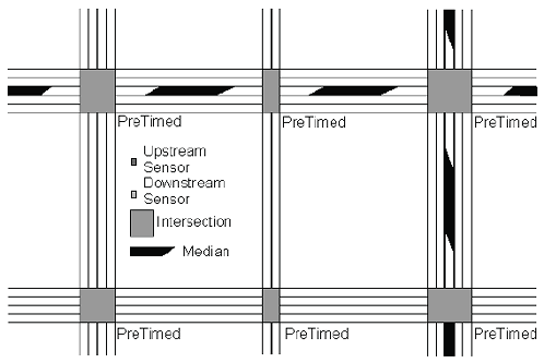
Figure L-1. Network sensor web density level 0.0—no sensors.
Systems may operate on fixed timing plans with no actuated phases. The systems may operate either as totally isolated systems or as TOD/DOW, in which precalculated, fixed timing plans are implemented accordingly.
This has a very low level of sensor density. Thus, a very low level of maintenance is needed. See Figure L-2 for a typical network layout.
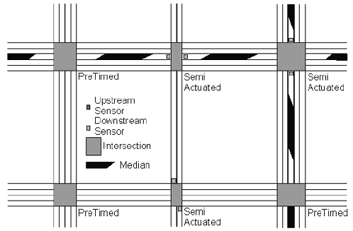
Figure L-2. Network sensor web density level 0.5—occasional minor movement stop bar detection.
These systems are TOD/DOW systems made more responsive to traffic by the incorporation of semiactuated and fully actuated controllers at key locations. The purpose of the semiactuated controllers is generally to minimize the breakup of progressive flow when side-street traffic is not present. The traffic actuated controller’s actuated signal settings may be varied by time of day and day of week. Generally only left turns and minor side streets are actuated.
This density level provides a low level of sensor density with up to one sensor per link. A low level of sensor maintenance is needed. See Figure L-3 for a typical network layout.
This density level is used for traffic adjusted systems. For this Handbook, a traffic adjusted system is defined as one in which a timing plan is selected based on a combination of TOD/DOW and the real demands of traffic. These systems require system sensors for volume plus weighted occupancy (VPLUSKO) or peak direction of flow data to choose timing plans. However, the timing plans are selected from a fixed library of timing plans previously calculated (either on line or off line). Examples of traffic adjusted systems are UTCS (Urban Traffic Control System) 1st Generation traffic responsive, UTCS 1.5 Generation and various closed loop systems. Periodic manual traffic counts are required for calibration of system sensors.
|
How to locate system detectors for traffic adjusted systems is described in “Locating Detectors for Advanced Traffic Control Strategies.”(4.5) These reports state that this kind of system “requires instrumentation on the entrance links and approximately every fourth block thereafter on arterials and on every third block within grid networks. Links that carry low volumes (peak hour volumes of less than 100 vph [vehicles per hour]/lane should not be instrumented …” |
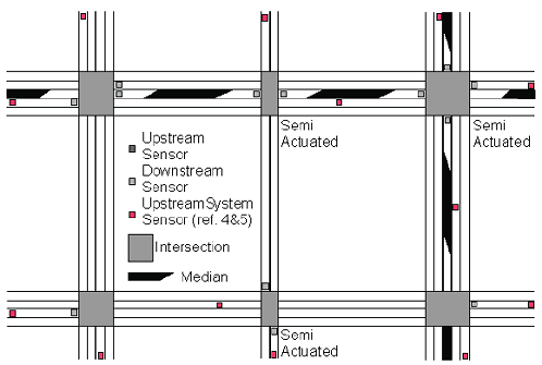 Figure L-3. Network sensor web density level 1.0 (UTCS 1.5, closed-loop systems—several minor movement without detectors). |
This density level provides a moderate sensor density with up to one sensor per link and additional sensors for actuated controllers. A moderate level of sensor maintenance required due to the greater density of system and traffic actuated sensors.
This level might be used for a traffic adjusted system that has been made more responsive to traffic by the incorporation of traffic actuated controllers. The actuated signal settings may be varied by time of day and day of week. Sensors are placed at key locations along with more intensive sensor placement at actuated locations. Periodic manual traffic counts are required. A moderate degree of sensor maintenance is also required due to the greater density of system and traffic actuated sensors. See Figure L-4 for a typical network layout.
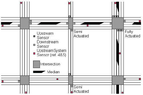
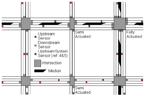
This density level provides a medium density of at least one system sensor per approach link. A medium level of sensor maintenance is required due to the greater density of system sensors. See Figure L-5 for a typical network layout.
|
UTCS 2 GC “requires instrumentation on all links between ‘major intersections which are defined as those intersections operating within the strategic optimization routine”(p. 84, ref. 5). |
Sensor Web Density Level 2.0 is applicable to simpler traffic responsive control systems found in arterial and closed loop systems. These systems are characterized by timing plans that are selected or computed based on real-time demands of traffic as detected by vehicle sensors. The plans are implemented at regular intervals of not less than 15 minutes (and rechecked at shorter intervals thereafter). Since traffic responsive systems have fixed offsets, changes of these plans more than once every 15 minutes may result in system degradation. An example of a system using a Level 2 density is UTCS 2nd Generation Traffic Responsive. Systems using Level 2 sensor web density and above are usually able to include some form of traffic prediction. Periodic manual calibration counts are required to obtain an accurate distribution of traffic across lanes for fully utilizing system sensors.
Note that some major phases may need dilemma zone protection. TxDOT has offered several publications describing different kinds of techniques and dilemma zone systems that might be useful.(6,7,8) The sensor network needed for dilemma zone protection is discussed under sensor web density level 3.0.
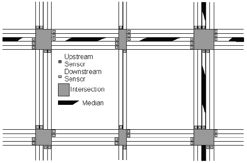
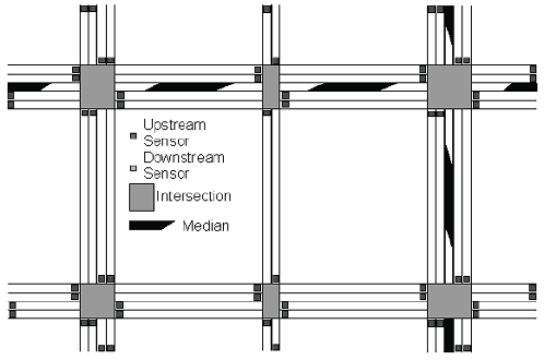
This level provides a high sensor density of at least one sensor per lane per link (as for example, the approach link for SCATS (Sydney Coordinated Adaptive Control System) or the departure leg of SCOOT (The split, cycle and offset optimization technique). Sensor web density level 2.5 requires a large amount of sensor and communications maintenance due to the heavy concentration of system sensors.
This density level might be used for traffic responsive systems. A traffic responsive system is defined as one in which key aspects of the timing plan may be altered between signal timing plan updates and timing plan updates are possible at least every 15 minutes. These would include the distributed intelligence traffic control system (DITCS) that uses timing plans but dynamically adjusts splits. Also, SCATS(9,10) updates intersection cycle length using the sensors at the stop line. SCATS allows for phase skipping. Sensor web density level 2.5 systems might typically include some form of traffic prediction. SCOOT(11,12) may make modest adjustments (<4 s) to the offset, split, and cycle in each cycle. See Figure L-6 for a typical network layout for SCATS and Figure L-7 for a typical network layout for SCOOT.
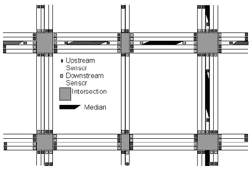
This density level has two or more sensors per lane per link. This requires a very high level of sensor and communications maintenance. See Figure L-8 for a typical network layout.
|
For ACS systems, the upstream sensors should be placed to provide a rolling 10-second traffic prediction window. This means at 10 seconds travel time distance upstream from the stop bar. This will be approximately 250 feet (76 m) at 25 ft/s (7.6 m/s).(14) |
Level 3 is applicable to traffic adaptive systems. A traffic adaptive system for this purpose is defined as one in which all signal timings are evaluated and changed based on forecasts of future traffic flow continuously in real time. A rolling prediction horizon of from 1 to 4 seconds to 20 seconds is a key element of traffic adaptive systems. A traffic adaptive system usually does not have offsets in the classical pretimed or traffic responsive sense. This is because the signal settings are in constant adaptation. Traffic adaptive systems are frequently distributed systems with the algorithms running in individual controllers and the controllers negotiating with each other over the settings. For example, RHODES requires an upstream, free-flow sensor and a downstream stop bar sensor and left turn bay sensors to operate at full efficiency. Thus, RHODES(13,15) and other ACS systems operate at a sensor web density level 3.0.
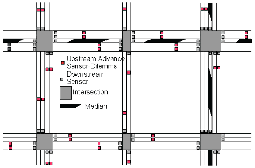
Sensor density level 3.0a is really a higher density version of sensor web density level 2. This level presents advance systems for dilemma zone protection on the major approaches and stop bar sensors for minor movement protection on minor approaches and phases. Density level 3.0a is illustrated in Figure L-9. Network Sensor Web Density Level 3.0a
Density level 3.0a is used by State highway departments on rural, high-speed State highways to help prevent red light running crashes. The upstream detectors on coordinated movements may also be used for volume-density operation. Volume-density, where it is configured correctly, is quite effective.
This is an enhancement of level 3.0. This level uses vehicle identification, classification and tracking sensors. It could be used for traffic responsive or traffic adaptive systems. This level uniquely identifies each vehicle entering a leg, know its classification, and know when that vehicle left the leg. The sensors to support this level are in research and development, and the first research networks are being built.
This is a hypothetical level that will become possible with the widespread adoption of DSRC (Dedicated Short-Range Communications), high-accuracy GPS, (Global Positioning System) and in-vehicle computers and communications. Each vehicle will regularly report its location, and possibly its destination, to the traffic management system. This would allow the creation of a new category of traffic control using long time horizon traffic prediction, which might be called, for example, traffic predictive control.
The higher the sensor density level number, the higher is the need for detectors. Level 0.0 density systems do not support real-time systems and do not need sensors. Level 0.5 systems only have sensors for locally actuated controllers.
The more variable and unpredictable the traffic, the greater is the need for sensors.
Closed-loop systems that use less communications to the central master and microcomputer-based masters can fit into many of the above categories. ACS Lite is a closed-loop subset of ACS and may utilize a sensor web density of level of 1.0 or 1.5.
Previous | Table of Contents | Next
FHWA-HRT-06-139 |