

Archived: Interstate Technical Group on Abandoned Underground Mines
Fourth Biennial Abandoned Underground Mine Workshop
Figures: Underground Mining and Its Surface Effects
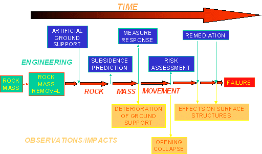
Figure 1. Schematic developments of mine effects.
Figure 2. Longwall coal face ripper. The overlying strata are of varying thickness and rock types (photo courtesy of David Young).
Figure 3. Folded coal and other sedimentary strata, Smokey River Coal Mine, Alberta (photo courtesy of Dave Young).
![Drawing shows longwall mining method. A drum shearer moves along a coal face as a chain conveyor carries the coal to one side to a belt conveyor in a transport drift. [Brady and Brown, 1985].](images/bet04.jpg)
Figure 4. Longwall mining method and ground reaction [Brady and Brown, 1985].
![Drawing shows mine roof supported by the longwall equipment shields. Immediately behind the equipment, the roof fails and collapses into the mined seam. [Whittaker and Reddish, 1989].](images/bet05.jpg)
Figure 5. Rock mass behavior above and behind longwall mining face support [Whittaker and Reddish, 1989].
![Schematic: Strata movement above a longwall panel [Kolebaevna, 1968] in Peng (1992).](images/bet06.gif)
Figure 6. Drawing shows bending and breaking of strata above a mined longwall panel. [Kolebaevna, 1968] in Peng (1992).
Figure 7. Longwall mining subsidence effect.
![Drawing shows rock mass movements associated with longwall mining. Overburden rock at the face moves horizontally toward the previously mined zone. Overburden rock behind the longwall equipment moves vertically downward. [Whittaker and Reddish, 1989].](images/bet08.jpg)
Figure 8. Generic ground and rock mass movements associated with longwall mining [Whittaker and Reddish, 1989].
![Graph shows subsidence from longwall mining in terms of width and depth of working. Subsidence increases as the width to depth ratio approaches 1.0. The rate of increase decreases as the ratio approaches 1.2 then levels off. [Orchard, 1956-57], in Whittaker and Reddish (1989).](images/bet09.jpg)
Figure 9. Subsidence from longwall mining in terms of width and depth of working [Orchard, 1956-57], in Whittaker and Reddish (1989).
![Surface subsidence profiles for dipping seams. Drawings show profiles for increasing angles of dip. The point of maximum subsidence moves farther down-dip as the angle of dip increases. [Whittaker and Reddish, 1989].](images/bet10a.jpg)
![Surface subsidence profiles for dipping seams. Drawings show profiles for increasing angles of dip. The point of maximum subsidence moves farther down-dip as the angle of dip increases. [Whittaker and Reddish, 1989].](images/bet10b.jpg)
Figure 10. Surface subsidence profiles for dipping seams [Whittaker and Reddish, 1989].
![Drawing of arching over longwall mining. [Whittaker and Reddish, 1989].](images/bet11.jpg)
Figure 11. Location of arching over longwall mining [Whittaker and Reddish, 1989].
![Drawings of subcritical, critical, and supercritical subsidence surface effects. For subcritical subsidence the positive strains are maximum at the edges and negative strains are maximum in the middle. For critical subsidence the positive strains are maximum at the edges and the negative strains are maximum between the edge and the center decreasing to zero at a point in the center. For supercritical subsidence the positive strains are maximum at the edges, the negative strains are maximum between the center and the edges and there is an area of no strain in the center. [Whittaker and Reddish, 1989].](images/bet12.jpg)
Figure 12. Subcritical, critical and supercritical subsidence surface effects [Whittaker and Reddish, 1989].
![Drawing of subsidence profile with multiple mined seams shows that the subsidence effects are cumulative. [Whittaker and Reddish, 1989].](images/bet13.jpg)
Figure 13. Subsidence surface profile with multiple seam situation [Whittaker and Reddish, 1989].
![Graph of subsidence factor versus mining depth in the Appalachian coalfield. The subsidence factor decreases linearly with increasing depth. [Peng, 1992].](images/bet14.jpg)
Figure 14. Subsidence factor versus mining depth in the Appalachian coalfield [Peng, 1992].
![Figure shows the slope curves for subcritical and critical subsidence. The slope for critical subsidence is about twice that for subcritical subsidence. [Brady and Brown, 1985].](images/bet15.jpg)
Figure 15. Mathematical form of longwall mining subsidence profile [Brady and Brown, 1985].
![Drawing shows that for a dipping seam the ground rotates into the extraction around a point down dip of the extraction. [Whittaker and Reddish, 1989].](images/bet16.jpg)
Figure 16. Generic strata movement over inclined longwall extraction [Whittaker and Reddish, 1989].
![Drawing shows that for a dipping seam the ground rotates into the extraction around a point down dip of the extraction. [Degirmenci et al., 1988] in Whittaker and Reddish (1989).](images/bet17.jpg)
Figure 17. Points of rotation of subsiding ground over dipping longwall mining extraction [Degirmenci et al., 1988] in Whittaker and Reddish (1989).
![Graphic description of strain in a dipping seam shows that strain is greatest on the down-dip side of the extraction. [Whittaker and Reddish, 1989].](images/bet18.jpg)
Figure 18. Strains and displacements associated with inclined longwall mining [Whittaker and Reddish, 1989].
![Drawing shows subsidence in sloping ground over a level mined seam and associated tension. Increasing the slope increases the tension zone on the up-slope side [Whittaker and Reddish, 1989].](images/bet19a.jpg)
![Drawing shows subsidence in sloping ground over a level mined seam and associated tension. Increasing the slope increases the tension zone on the up-slope side [Whittaker and Reddish, 1989].](images/bet19b.jpg)
Figure 19. Inclined surface subsidence [Whittaker and Reddish, 1989].
![Drawing shows subsidence effects of mining seams close to an inclined surface. See text. [Whittaker and Reddish, 1989]](images/bet20a.jpg)
![Drawing shows subsidence effects of mining seams close to an inclined surface. See text. [Whittaker and Reddish, 1989]](images/bet20b.jpg)
Figure 20. Subsidence effects of mining seams close to inclined surface [Whittaker and Reddish, 1989]
![Drawing shows stresses resulting from mine extraction. Vertical compressive forces go around an arch over the mined void. Horizontal compressive forces exist within the arch above the mined void. Bending moment forces exist in the roof rock immediately above the void. Vertical shear forces exist in the mine extraction walls. [Whittaker and Reddish, 1989].](images/bet21.jpg)
Figure 21. Narrow roadway roof stability conditions [Whittaker and Reddish, 1989].
![Drawing shows subsidence hole and subsidence trough. See text. [Whittaker and Reddish, 1989].](images/bet22.jpg)
Figure 22. Common forms of subsidence in room and pillar coal mining [Whittaker and Reddish, 1989].
![Contour map of subsidence trough. See text. [O'Connor et al., 1996].](images/bet23.jpg)
Figure 23. Surface troughs over room and pillar mining, 0.025 m contour interval [O'Connor et al., 1996].
![Drawing shows stages of chimney caving of a mine roof. See text for description. [Whittaker and Reddish, 1989].](images/bet24.jpg)
Figure 24. Chimney caving height calculations [Whittaker and Reddish, 1989].
![Graph of the time aspects of subsidence shows that subsidence rate increases with increasing extraction rate. See text. [Wittaker and Reddish, 1989].](images/bet25.jpg)
Figure 25. Time aspects of subsidence over longwall mining [Wittaker and Reddish, 1989].
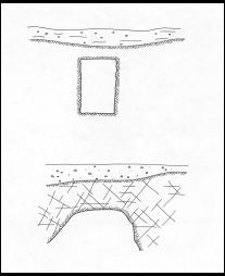
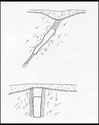
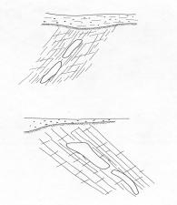
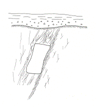
Figure 26. Common rock mass environments for metal mines [Bétournay, 1995]. Top: Poorly jointed, jointed and blocky, weak schistose orebody and competent walls, competent orebody, weak schistose walls. Bottom: Generally foliated, slaty, well developed stratification, fault -weakened, altered rock mass.
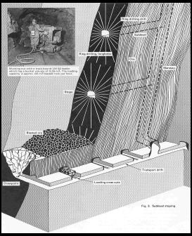
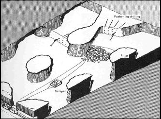
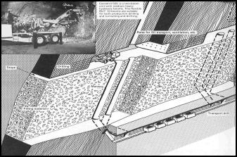
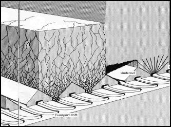
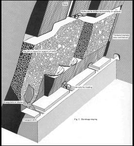
Figure 27. Common metal mining methods [Atlas Copco, 1973]. Top to bottom: Sublevel stoping, inclined room and pillar, shrinkage stoping, block caving, cut-and-fill.
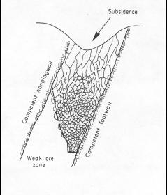
Figure 28. Common failure mechanisms of hard rock mines [Bétournay, 1995]. Top to bottom: Plug failure, destratification, ravelling failure, chimneying disintegration, Rock mass caving.
![Schematic of computer model of distinct element simulation of block caving showing simulated breakup of rock into distinct pieces and their progressive downward movement. [Voegele et al., 1978] in Brady and Brown, 1985.](images/bet29.jpg)
Figure 29. Distinct element simulation of block caving [Voegele et al., 1978] in Brady and Brown, 1985.
![Ellipsoid drawing pattern for caved rock. See text. [Janelid and Kvapil, 1966].](images/bet30.jpg)
Figure 30. Ellipsoid drawing pattern for caved rock [Janelid and Kvapil, 1966].