| << Previous | Contents | Next >> |
Geotechnical Aspects of Pavements Reference Manual
Chapter 7.0 Design Details And Construction Conditions Requiring Special Design Attention (continued)
7.3 Base Layers: Requirements, Stabilization & Reinforcement
The function of the base course varies according to the type of pavement, as was described in Chapter 1. Under rigid pavements, the base course is used to: (1) provide uniform and stable support, (2) minimize damaging effects of frost action, (3) provide drainage, (4) prevent pumping of fine-grained soils at joints, (5) prevent volume change of the subgrade, (5) increase structural capacity of the pavement, and (6) expedite construction. Under flexible pavements, the prime function of the base course is to structurally improve the load-supporting capacity of the pavement by providing added stiffness and resistance to fatigue, as well as to provide a relatively thick layer to distribute the load through a finite thickness of pavement. The base may also provide drainage and give added protection against frost action where necessary.
To meet these functional requirements, the base course as a minimum should have the following characteristics:
- To prevent pumping, a base course must be either free draining or it must be highly resistant to the erosive action of water. Erodibility is covered in more detail in the next section.
- To provide drainage, the base course may or may not be a well-graded material, but it should contain little or no materials finer than a 0.075 mm (No. 200) sieve. It may sometimes be stabilized with asphalt or cement.
- A base course design for frost action should be non-frost susceptible and free draining.
- To improve resistance to deformation and improve structural support or reduce the thickness, it may be desirable to stabilize the base course with asphalt or cement, as reviewed in Section 7.3.2 and 7.3.3, or to reinforce it with geosynthetics, as reviewed in Section 7.3.4.
- A base course need not be free draining to provide structural capacity, but it should be well-graded and should resist deformation due to loading.
The aggregate used for base must be hard, durable material. As a minimum, the aggregate should meet the following requirements:
- The aggregate should have at least two fractured faces; preferably, it should consist of 98% crushed stone.
- The L.A. abrasion wear should not exceed 45% as determined by AASHTO T 96, Resistance to Abrasion of Small Size Coarse Aggregate by Use of Los Angeles Machine.
- The soundness loss percent should not exceed 12 or 18%, as determined by the sodium sulfate or magnesium sulfate tests, respectively. The test should be performed in accordance with AASHTO T 104, Soundness of Aggregate by the Use of Sodium Sulfate or Magnesium Sulfate (see Chapter 5).
- For permeable base, the gradation of this layer should enable free movement of water with a minimum permeability value around 300 m/day (1,000 ft/day) (see Section 7.2) and the material passing the 0.425 mm (No. 40) sieve should be non-plastic in accordance with AASHTO T 90, Determining the Plastic Limit and Plasticity Index of Soils.
7.3.1 Erodibility of Bases
Preventing significant erosion of the base and subbase materials is very important for the control of moisture-related distresses, such as pumping and faulting in JPCP and punchouts in CRCP, as discussed in NCHRP 1-37A. Erodibility is the loss of base material due to hydraulic action, most often at the joints in rigid pavements, but also along the edge of both rigid and flexible pavements. The condition is related to the durability of the base in relation to its potential to break down under dynamic traffic loads, climatic conditions, environmental effects, as well as water action. As truck traffic increases, a more erosion resistant base is required, along with more adequate joint load transfer design (e.g., use of dowels in joints). Traffic level is a very critical factor in the consideration of base/subbase course erosion, especially considering that the base/subbase under PCC slabs of reconstructed projects will likely receive 10 to 20 times more load repetitions over their design life than in the past.
While the base course is the layer most often affected by erosion, any layer directly beneath a treated base can experience serious erosion. There are many examples of the erosion of fine grained soils beneath a stabilized base course causing loss of support and joint faulting. Thus, some agencies now place a dense graded granular subbase layer between the base and compacted subgrade to reduce this problem. Other agencies stabilize the top layer of a fine-grained soil with lime to reduce this problem; however, this approach must produce a sufficiently hard material with adequate compressive strength and uniformity along the project. Geotextiles are also used as separation layers to hold the subgrade materials in place. Another alternative that has been used successfully is to place a layer of recycled crushed PCC beneath the dense treated base.
The NCHRP 1-37A guide provides guidance for assessing the erodibility potential of various materials used in new JPCP and CRCP design and in PCC overlays of existing flexible or rigid pavements. The effect of erosion is considered empirically in the form of erodibility classification assessment for specific design levels. The design procedure provides the framework for which erosion can be considered on a more mechanistic basis in the future (such as iterative month-by-month damage accumulation, and inclusion of Level 1 laboratory erosion test). Tables 7-6, 7-7, and 7-8 provide the Material Classification requirements for Level 1, Level 2, and Level 3 design, respectively.
| Erodibility Class | Material Description and Testing |
|---|---|
| Class based on the material type and test results | Test not fully developed for nationwide uses; thus Level 1 cannot be implemented at this time. The tests currently being considered to assess the erodibility of paving materials include:
|
| Erodibility Class | Material Description and Testing |
|---|---|
| 1 |
|
| 2 |
|
| 3 |
|
| 4 | Unbound crushed granular material having dense gradation and high quality aggregates. |
| 5 | Untreated soils (PCC slab placed on prepared/compacted subgrade). |
| Erodibility Class | Material Description and Testing |
|---|---|
| 1 |
|
| 2 |
|
| 3 |
|
| 4 | Unbound crushed granular material having dense gradation and high quality aggregates. |
| 5 | Untreated subgrade soils (compacted). |
7.3.2 Bound Bases
In order to achieve the highest erodibility levels, stabilized base or subbase materials often produced by the addition of a sufficient quantity of stabilizing agent (usually cement or asphalt) to produce materials with significant tensile strength (e.g., Erodibility Class 1a in Table 7-7). Such materials are considered to be bound bases and have a substantial increase in structural capacity over that of unbound and modified (treated) bases. Bound bases or subbases are not considered to be geotechnical materials, and are not covered in this manual. Users are referred to NHI courses on pavements (e.g., NHI 131033) for additional information.
7.3.3 Modified (or Treated) Bases
The addition of cement or asphalt (typically less than 5%) to stabilize unbound base or subbase with the primary purpose of improving the stability for construction are considered to be modified or treated bases. Modified materials are usually considered to behave structurally as unbound granular material. These bases or subbases are considered to be geotechnical materials. Stabilization is most often required for open graded (permeable) bases (OGB), which tend to rut and weave under construction activities. Tables 7-9 and 7-10 provide the recommendations for asphalt-treated bases and cement-treated bases, respectively.
The strength of cement-treated bases will depend in part on adequate curing during construction. The mixture must be well compacted at optimum moisture content, and adequate density must be obtained throughout the layer. Density control will also be important for the uniformity of asphalt-treated base materials. Although stabilization is often used to reduce the thickness of the base, it should be recognized that thin bases (less than 150 mm (6 in.) thickness) are often extremely difficult to construct to the exact depth, creating the potential for very thin base layers in localized areas. Construction of thin bases requires a very competent subgrade or a good working platform (as reviewed in Section 7.6). Construction quality control for cement- and asphalt-treated materials is reviewed in Chapter 8.
| Specification | Requirement | Test Method |
|---|---|---|
| Aggregate | (a) hard, durable material with at least two fractured faces; preferably, consisting of 98% crushed stone. | Visual Classification |
| (b) L.A. abrasion wear should not exceed 45%. | AASHTO T 96 | |
| (c) Soundness loss percent should not exceed 12 as determined by the sodium sulfate, or 18% by the magnesium sulfate tests. | AASHTO T 104, Soundness of Aggregate by the Use of Sodium Sulfate or Magnesium Sulfate | |
| AC content | AC content must ensure that aggregates are well coated. Minimum recommended AC content is between 2.5 - 3% by weight. Final AC content should be determined according to mix gradation and film thickness around the coarse aggregates. | ASTM D 2489, Test Method for Degree of Particle Coating of Bituminous-Aggregate Mixtures. |
| AC grade | A stiff asphalt grade (typically 1 grade stiffer than the surface course is recommended). | Penetration, viscosity, or Superpave binder testing can be performed to determine AC grade. |
| Anti-stripping | Anti-stripping test should be performed on all AC treated materials. | AASHTO T283, Resistance of Compacted Bituminous Mixture to Moisture Induced Damage. |
| Anti-stripping Agents | Aggregates exhibiting hydrophilic characteristics can be counteracted with 0.5 - 1% lime. | NCHRP Report 274. |
| Permeability | Minimum mix permeability: 300 m/day (1000 ft/day). | AASHTO T 3637, Permeability of Bituminous Mixtures. |
| Specification | Requirement | Test Method |
|---|---|---|
| Aggregate | (a) Hard, durable material with at least two fractured faces; preferably, consisting of 98 percent crushed stone. | Visual Classification |
| (b) L.A. abrasion wear should not exceed 45%. | AASHTO T 96-94 | |
| (c) Soundness loss percent should not exceed 12 or 18%, as determined by the sodium sulfate or magnesium sulfate tests, respectively. | AASHTO T 104-86, "Soundness of Aggregate ...Use of Sodium Sulfate or Magnesium Sulfate" | |
| Cement | Portland cement content selected must ensure that aggregates are well coated. An application rate of 130 to 166 kg/m3 (220 to 285 lb/yd3) is recommended. | Must conform to the specification of AASHTO M 85, Portland Cement |
| Water-to- cement ratio | Recommended water-to-cement ratio to ensure strength and workability: 0.3 to 0.5. | |
| Workability | Mix slump should range between 25 - 75 mm (1 - 3 in.). | |
| Cleanness | Use only clean aggregates | |
| Permeability | Minimum mix permeability: (300 m/day)1,000 ft/day. |
7.3.4 Base Reinforcement
A more recent form of stabilization is the use of geosynthetics (primarily geogrids) to reinforce the base for flexible pavement systems, which has been found under certain conditions to provide significant improvement in performance of pavement sections. The principal effect of reinforcement in base-reinforced flexible pavements is to provide lateral confinement of the aggregate layer. Lateral confinement arises from the development of interface shear stresses between the aggregate and the reinforcement, which, in turn, transfers load to the reinforcement. The interface shear stress present when a traffic load is removed continues to grow with traffic load applications, meaning that the lateral confinement of the aggregate increases with increasing load applications. Increases in traffic volume up to a factor of 10 to reach the same distress level (25-mm (1 in.) rutting) have been observed for reinforced sections, versus unreinforced sections of the same design asphalt and base thickness (Berg et al., 2000). Table 7-11 provides a summary of the conditions for which various geosynthetic products should be considered for this application.
| Roadway Design Conditions | Geosynthetic Type | ||||||
|---|---|---|---|---|---|---|---|
| Subgrade | Base / Subbase Thickness1 (mm) | Geotextile | Geogrid2 | GG-GT Composite | |||
| Nonwoven | Woven | Extruded | Knitted or Woven | Open- Graded Base3 | Well-Graded Base | ||
| Soft (CBR < 3) (MR < 30 MPa) | 150 - 300 |  |  |  |  |  |  |
| > 300 |  |  |  |  |  |  | |
| Firm - Vy. Stiff (3 ≤ CBR ≤ 8) (30 ≤ MR ≤ 80) | 150 - 300 |  |  |  |  |  |  |
| > 300 |  |  |  |  |  |  | |
|
KEY:
NOTES:
| |||||||
Current design methods for flexible pavements reinforced with a geosynthetic in the unbound aggregate base layer are largely empirical methods based on a limited set of design conditions over which test sections have been constructed (i.e., AASHTO 4E-SR Standard of Practice Guidelines for Base Reinforcement). These design methods have been limited in use due to 1) absence of nationally recognized reinforced base design procedure, 2) narrow range of test section design conditions from which the method was calibrated, and 3) proprietary design methods pertaining to a single geosynthetic product. Recently FHWA sponsored a study to develop an interface for including geosynthetic base reinforcement in mechanistic empirical design, consistent with the NCHRP 1-37A model. This work is currently in review, but shows excellent promise for the incorporation of these methods into pavement design.
In the interim, AASHTO 4E includes a design approach that relies upon the assessment of reinforcement benefit as defined by a Traffic Benefit Ratio (TBR) or a Base Course reduction Ratio (BCR). TBR is defined as the ratio of the number of traffic loads between an otherwise identical reinforced and unreinforced pavement that can be applied to reach a particular permanent surface deformation of the pavement. BCR defines the percentage reduction in the base course thickness of a reinforced pavement such that equivalent life (e.g., surface deformation) is obtained between the reinforced and the unreinforced pavement with the greater aggregate thickness. The philosophy of this approach is one in which applicability of the technology and reinforcement benefits are assessed by empirical considerations. Reinforcement benefit defined in this manner is then used to modify an existing unreinforced pavement design.
The proposed design procedure in AASHTO 4E follows the steps listed below:
- Step 1. Initial assessment of applicability of the technology.
- Step 2. Design of the unreinforced pavement.
- Step 3. Definition of the qualitative benefits of reinforcement for the project.
- Step 4. Definition of the quantitative benefits of reinforcement (TBR or BCR).
- Step 5. Design of the reinforced pavement using the benefits defined in Step 4.
- Step 6. Analysis of life-cycle costs.
- Step 7. Development of a project specification.
- Step 8. Development of construction drawings and bid documents.
- Step 9. Construction of the roadway.
Step 1 involves assessing the project-related variables given in Table 7-11 and making a judgment on whether the project conditions are favorable or unfavorable for reinforcement to be effective and what types of reinforcement products (as defined in Table 7-11) are appropriate for the project.
Step 2 involves the design of a conventional unreinforced typical pavement design cross section or a series of cross sections, if appropriate, for the project. Any acceptable design procedure can be used for this step.
Step 3 involves an assessment of the qualitative benefits that will be derived by the addition of the reinforcement. The two main benefits that should be assessed are whether the geosynthetic will be used for an extension of the life of the pavement (i.e., the application of additional vehicle passes), a reduction of the base aggregate thickness, or a combination of the two. Berg et al. (2000) has listed additional secondary benefits that should also be considered.
Step 4 is the most difficult step in the design process and requires the greatest amount of judgment. This step requires the definition of the value, or values, of benefit (TBR and/or BCR) that will be used in the design of the reinforced pavement. The definition of these benefit values for a range of design conditions is perhaps the most actively debated and most currently studied topic within this field. Given the lack of a suitable analytical solution for the definition of these terms, Berg et al. (2000) has suggested that these values be determined by a careful comparison of project design conditions, as defined in previous steps, to conditions present in studies reported in the literature. The majority of these studies have been summarized in Berg et al. (2000) in a form that allows direct comparison to known project conditions. In the absence of suitable comparison studies, an experimental demonstration method involving the construction of reinforced and unreinforced pavement test sections has been suggested and described in Berg et al. (2000), and may be used for the definition of benefit for the project conditions. The reasonableness of benefit values should be carefully evaluated such that the reliability of the pavement is not undermined.
Step 5 involves the direct application of TBR or BCR to modify the unreinforced pavement design defined in Step 2. TBR can be directly used to define an increased number of vehicle passes that can be applied to the pavement, while BCR can be used to define a reduced base aggregate thickness such that equal life results. Within the context of an AASHTO pavement design approach, it is possible to calculate a BCR knowing a TBR and vise versa for the specific project design conditions, however this approach has not been experimentally or analytically validated.
With the unreinforced and reinforced pavement designs defined, a life-cycle cost analysis should be performed to assess the economic benefit of reinforcement. This step will dictate whether it is economically beneficial to use the geosynthetic reinforcement. Remaining steps involve the development of project specifications, construction drawings, bid documents, and plans for construction monitoring. Berg et al. (2000) has presented a draft specification that may be adopted for this application.
Even though the application of geosynthetic reinforcement of flexible pavements has been proposed and examined over the past 20 years, research in this area is quite active, meaning that new design methods should be expected in the near future. These new design methods will hopefully provide less empirical methods for assessing reinforcement benefit and be expressed as a function of the variables that are known to influence benefit.
7.4 Compaction
Compaction of the subgrade, unbound base, and subbase materials is a basic design detail and is one of the most fundamental geotechnical operations for any pavement project. Compaction is used to increase the stiffness and strength, decrease the permeability, and increase the erosion resistance of geomaterials. Compaction can also reduce the swelling potential for expansive soils. Thus, the intent of compaction is to maximize the soil strength (and minimize the potential volume change) by the proper adjustment of moisture and the densification at or near the ideal moisture content, as discussed in this section.
In most instances, once heavy earthwork and fine grading is completed, the uppermost zone of subgrade soil (roadbed) is improved. The typical improvement technique is by means of water content adjustments and densification by compaction. Higher density requirements are routinely established for the top two feet of at-grade roadbeds and for embankments. The soil in cut areas may need to be undercut and backfilled to obtain the strength and uniformity desired. Heavy proof rolling equipment (270 to 450 kN (30 to 50 tons)) can be used to identify areas of non-uniform support in prepared subgrades. Proofrolling and other field construction aspects of compaction are covered in Chapter 8. Perhaps the most common problem arising from deficient construction is related to moisture-density control, which can be avoided or at least minimized with a thorough plan and execution of the plan as it relates to QC/QA during construction, as reviewed in Chapter 8. This plan should pay particular attention to proper moisture content, proper lift thickness for compaction, and sufficient configuration (e.g., weight and width) of the compaction equipment utilized.
7.4.1 Compaction Theory
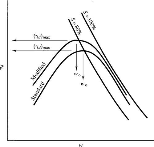
The basic engineering principles of soil compaction date back to work by Proctor in the 1930s. Compaction can be performed in the laboratory using static, kneading, gyratory, vibratory, or impact compactors. Each method has its advantages and disadvantages, but impact compaction using a falling hammer is the standard in practice today. Standard laboratory compaction tests are described in more detail in Chapter 5. In these tests, soil is mixed with water at a range of moisture contents w and compacted using a specified compaction energy (e.g., ft-lbs/ft3 or joules/m3). Figure 7-11 illustrates the effect of compaction energy on laboratory compaction curves. As described in Chapter 5, the Modified Proctor compaction test (ASTM D1557/ AASHTO T-180) has a compaction energy of 2,700 kN-m/m3 (56,000 ft-lb/ft3), which is nearly 5 times the compaction energy of 600 kN-m/m3 (12,400 ft-lb/ft3) in the Standard Proctor test (ASTM D698/AASHTO T-99). Likewise, increased compaction energy in the field will increase the maximum dry unit weight and decrease the associated optimum water content.
Figure 7-11. Effect of compaction energy on compaction curves (Coduto, 1999).
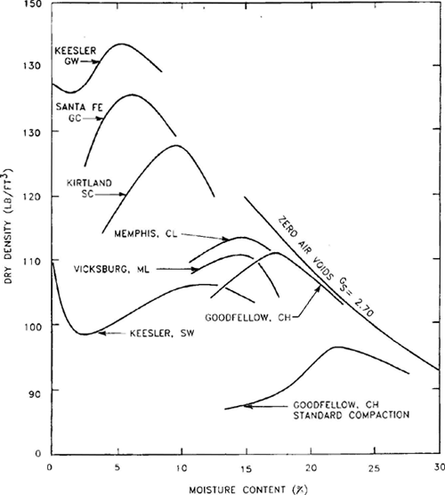
Different soils will generally have differently shaped compaction curves. This fact will aid in identifying the corresponding laboratory curve for materials encountered in the field. Figure 7-12 shows typical compaction curves for several different soils. Coarser, granular soils typically have fairly steep compaction curves, with large changes in density for small changes in moisture content, while highly plastic clays exhibit fairly flat compaction curves. The maximum dry density is higher for coarser soils and the optimum moisture content is lower. Some cohesionless soils will also exhibit two peaks in the compaction curve; one at very dry conditions, where there are no capillary tensions to resist the compaction effort, and the other at the optimum moisture content, where optimum lubrication between particles occurs.
Figure 7-12. Laboratory compaction curves for different soils (Rollings and Rollings, 1996).
Nearly all compaction specifications are based on achieving a minimum dry unit weight in the field. This is usually expressed in terms of the relative compaction CR:
(7.5)| CR = | γd | × 100% |
| ( γd )max |
in which γd is the dry unit weight achieved in the field and (γd)max is the maximum dry unit weight as determined from a specified laboratory compaction test.
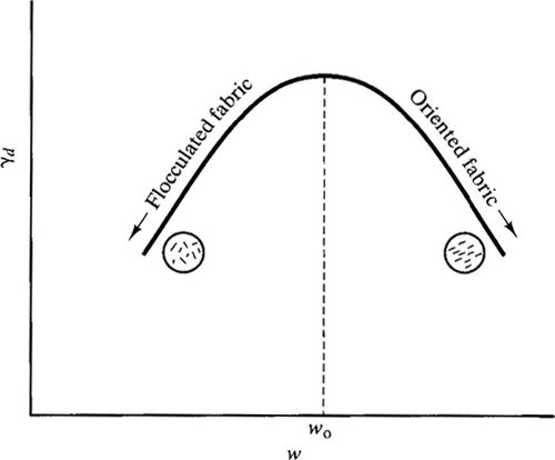
The water content at compaction is also sometimes specified because of its effect on soil fabric, especially for clays. Clays compacted dry of optimum have a flocculated fabric (see Figure 7-13), which generally corresponds to higher permeability, greater strength and stiffness, and increased brittleness. Conversely, clays compacted wet of optimum to the same equivalent dry density tend to have a more oriented or dispersed fabric, which typically corresponds to lower permeability, lower strength and stiffness, but more ductility.
Figure 7-13. Effect of compacted water content on soil fabric for clays (Coduto, 1999).
7.4.2 Effect on Soil Properties
The principal effects of compaction on soil properties are as follows:
- Density: As described in the preceding sections, the most direct measurable effect of compaction is an increase in soil density. Typical laboratory values of maximum dry density values and optimum moisture contents for different soils were summarized in Chapter 5, Table 5-18 and 5-19.
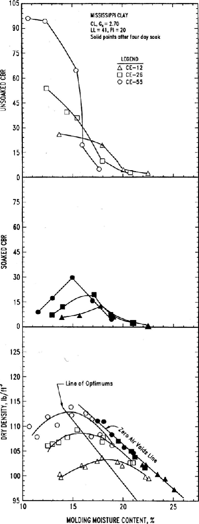
- Strength: Intuitively, one expects strength to increase with compaction energy and to be larger at low water contents than at high values. Figure 7-14 summarizes typical strength versus water content and compaction energy for a lean clay where strength is quantified by CBR (Rollings and Rollings, 1996). The data in the figure generally confirm intuitive expectations. The strength dry of the optimum water content is larger for higher compaction energies, as expected, and is up to an order of magnitude higher than the strength when compacted wet of optimum. Note, however, that higher compaction energies can produce slightly lower strength values when a fine-grained soil is compacted at water contents higher than the optimum. Also note that the strength in the figure is based on unsaturated soils. If material compacted dry of optimum becomes saturated, a significant decrease in strength can occur, with strengths even less than that of the same soil compacted wet of optimum. Large changes in strength upon wetting are associated with fine-grained silts and clays, and are less pronounced or even negligible in coarse-grained soils (Rollings and Rollings, 1996).
Figure 7-14. Strength as measured by CBR and dry density vs. water content for laboratory impact compaction (Rollings and Rollings, 1996).
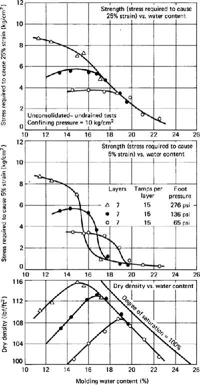
- Stiffness: Figure 7-15 summarizes typical stiffness versus water content and compaction energy behavior for clays, where stiffness is defined as the stress required to case 5% and 25% axial strain in a triaxial compression test (Seed and Chan, 1959). Stiffness increases with compaction energy when compacted dry of optimum and is largely independent of compaction energy when compacted wet of optimum. The stiffness dry of optimum is also substantially larger than when compacted wet of optimum, as would be expected. Again however, a significant decrease in stiffness can occur if the material becomes saturated to the extent that the stiffness could be less than that of the soil compacted wet of optimum.
Figure 7-15. Stiffness as a function of compactive effort and water content (after Seed and Chan, 1959; from Holtz and Kovacs, 1981).
- Permeability: Permeability at constant compactive effort decreases with increasing water content and reaches a minimum at about the optimum moisture content. The permeability when compacted dry of optimum is about an order of magnitude higher than the value when compacted wet of optimum.
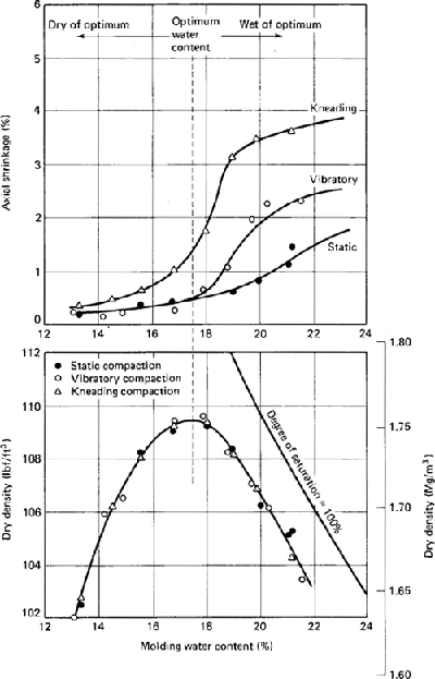
- Swelling/Shrinkage Potential: Swelling of compacted clays is greater when compacted dry of optimum. Dry clays have a greater capacity to absorb water, and thus swell more. Soils dry of optimum are in general more sensitive to environmental influences, such as changes in water content. The situation is just the opposite for shrinkage (Figure 7-16), where samples compacted wet of optimum exhibit the highest shrinkage strains as water is removed from the soil.
Figure 7-16. Shrinkage as a function of water content and type of compaction (after Seed and Chan, 1959; from Holtz and Kovacs, 1981).
| << Previous | Contents | Next >> |

