U.S. Department of Transportation
Federal Highway Administration
1200 New Jersey Avenue, SE
Washington, DC 20590
202-366-4000
Challenge: Bridge scour is the leading cause of bridge failures in the U.S. Current methodologies for predicting scour depths around bridge foundations in the river or coastal environments employ empirical equations assuming stream beds with uniformly-graded, non-cohesive soils such as sand, which may result in overly conservative scour depth estimates. Most stream beds are composed of layers of different types of soils which can include sand, silt, clay or rock and every material type responds differently to erosive forces. There is a need to assess the erodibility of such layers to improve the accuracy of the scour estimate.
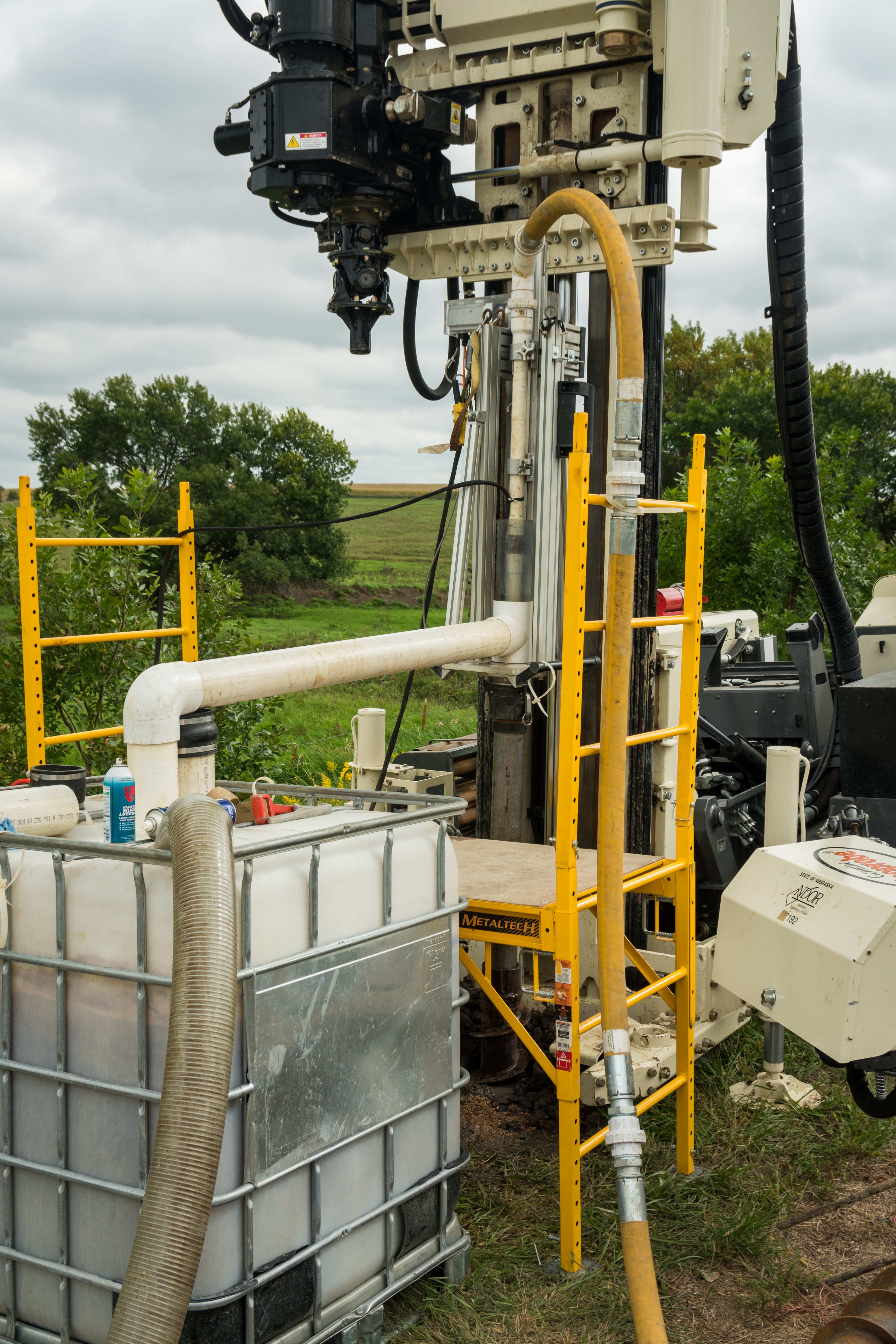
Technology: The In-Situ Scour Testing Device is designed to determine the erodibility of soil layers consisting of fine-grained cohesive soils. The device consists of an erosion head that is placed inside a conventional drill casing that is used for standard subsurface geotechnical soil investigations. The erosion head measures the soil erosion rate resulting from flowing water that is pumped through the head at a constant flow rate and with a consistent gap between the soil and the head. By measuring erosion rates for the foundation soils the critical shear stress, which represents the erosion resistance of the soil layer, can be obtained. The result will be more cost-effective foundation designs, greater reliability and resiliency in bridge performance, and increased safety for the traveling public.
Activities Funded: Final development of the ISTD systems and 18 demonstration showcases
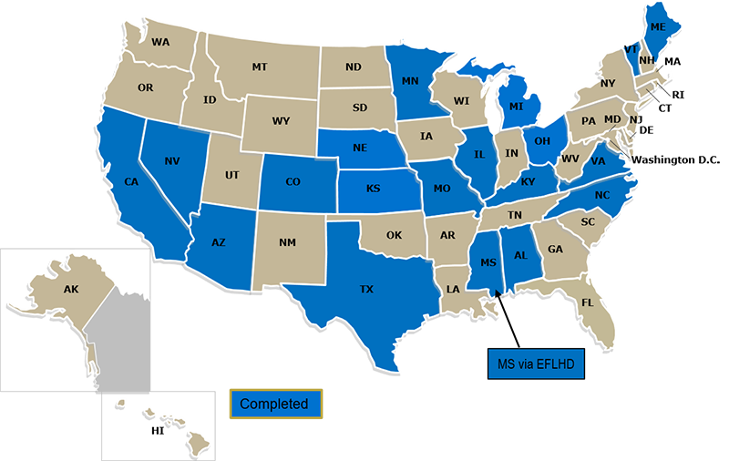
Demonstrations Completed: Factsheets containing an overview of the demonstration conducted at each site are linked below.
Future Progress: Following the successful demonstrations of the ISTD technology, the FHWA Hydraulics Research Laboratory established a Transportation Pooled Fund (TPF) study, TPF-5(461), Soil and Erosion Testing Services for Bridge Scour Evaluations to build upon the AMR project. This TPF study allows FHWA to continue partnering with State DOTs to conduct soil erosion testing at future bridge sites with potential layers of cohesive material. TPF-5(461) also provides the framework for FHWA to fabricate an ISTD device for a State DOT to partner with a local university and directly implement the technology into their scour research.
Further Information: https://highways.dot.gov/turner-fairbank-highway-research-center/labs/hydraulics
https://www.pooledfund.org/Details/Study/688
NextScour Case Study: The Lafayette Avenue Bridge Over the Saginaw River in Bay City, Michigan
Contact:
Ryan Lizewski
FHWA, Hydraulic Engineer
ryan.lizewski@dot.gov
202-951-0374
Khalid Mohamed
FHWA, Senior Geotechnical Engineer
khalid.mohamed@dot.gov
202-366-0886
Justice Maswoswe
FHWA, Senior Geotechnical Engineer
justice.maswoswe@dot.gov
667-239-0878
James Pagenkopf
FHWA, Research Hydraulic Engineer
James.Pagenkopf@dot.gov
202-493-7080
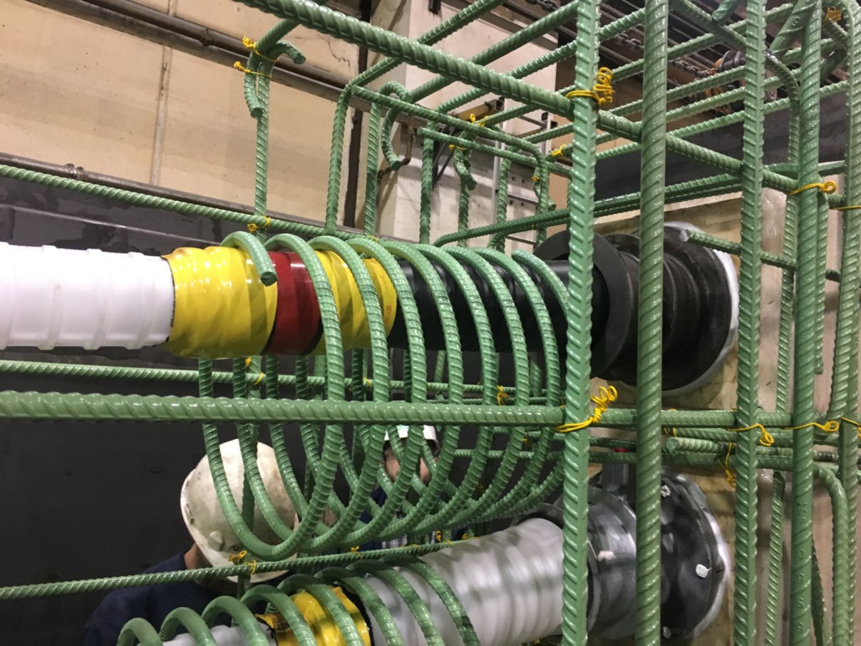
Need: Post-tensioning (PT) tendons provides the primary load carrying capacity in bridges and consequently there is great interest from owners to assess their in-service condition. However, inspection of a typical PT tendon is currently very difficult due to its multiple layers of encasement which typically include PT grout, PT duct, reinforcing steel and structural concrete.
Technology: EIT’s are a new non-destructive evaluation (NDE) technology that provides bridge owners with the highest level of corrosion protection and long-term monitoring on the PT tendon. The NDE readings can indicate that a PT system is puncture and damage free (fully encapsulated) which will provide bridge owners with a high level of assurance that the PT system, as installed, is highly protected against corrosion attack.
Activities Funded: demonstration showcases
Lehigh County, Pennsylvania completed the first U.S installation of electrically isolated PT tendons (EIT'S) to perform long-term monitoring of corrosion. Five EIT's total extending the full 542-foot length of the Coplay Northampton bridge were installed. Each EIT installed met the required electrical resistance threshold after installation, achieved full isolation, and is fully encapsulated and protected to the highest level possible. In addition to providing enhanced corrosion protection, the electrical isolation provides the opportunity to monitor each tendon's encapsulation quality and possible corrosion initiation through the bridges service life. The bridge was opened to traffic in the fall 2019. View article.
Contact:
Reggie Holt
FHWA Concrete Bridge Specialist
Reggie.Holt@dot.gov
202-366-4596
Need: Bridge engineers are seeking new ways to build better bridges, reduce work zone travel delays, and improve repair techniques thereby reducing maintenance. Additionally, owners are challenged with replacing critical bridge components (particularly bridge decks) during limited or overnight road closure periods.
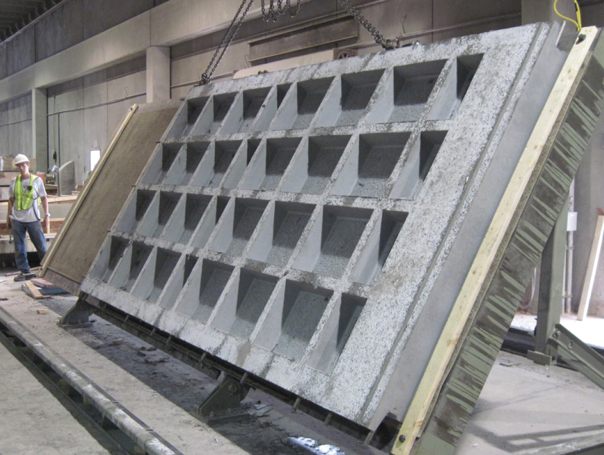
Technology: Precast panels manufactured from UHPC can provide significant durability improvements to bridge decks due to the high strength, extremely low permeability, and improved connection details inherent in the system. This technology results in reduced construction time for new and rehabilitated bridges, the ability to upgrade the load-carrying capacity of existing bridges, and improved durability of bridge decks. UHPC Connections for Prefabricated Bridge Elements and Systems was promoted in two rounds of the Every Day Counts Initiative.
Activities Funded: Coreslab Structures manufactured waffle bridge deck panels with UHPC and they were installed with field cast UHPC joints on a bridge in Wapello County, Iowa.
Further Information: https://www.fhwa.dot.gov/hfl/partnerships/bridgetech.cfm
Contact:
Ben Graybeal
FHWA Turner Fairbank Highway Research Center
Benjamin.Graybeal@dot.gov
202-493-3122
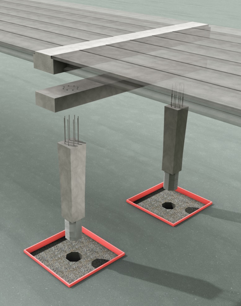
Need: Prefabricated bridge bents, also known as piers, have not been used in seismic regions because accepted methods of making connections that are both structurally robust and quick to assemble were not known and were not addressed in design specifications.
Technology: To construct precast elements in high seismic zones requires ductile detailing, which permits the structure to deform rather than to experience sudden unexpected brittle failure. The connections are made with a small number of large-diameter reinforcing bars that are grouted into larger-diameter ducts. This technology allows the main elements of bridge bents to be prefabricated on-site. The segments are then moved into place and assembled to form the bents, greatly reducing construction time and traffic delays.
Activities funded: Laboratory testing of column-to-spread footing connections and column-to-drilled shaft connections; development of design specifications; demonstration of the first U.S installation, Washington State, to use precast, segmental construction for bridge bents in a high seismic region. The design specifications developed under this project contributed to AASHTO’s 2018 publication of the first LRFD Guide Specifications for Accelerated Bridge Construction, which covers seismic design across the country.
Further Information: https://www.fhwa.dot.gov/hfl/partnerships/bridgetech.cfm
Contact:
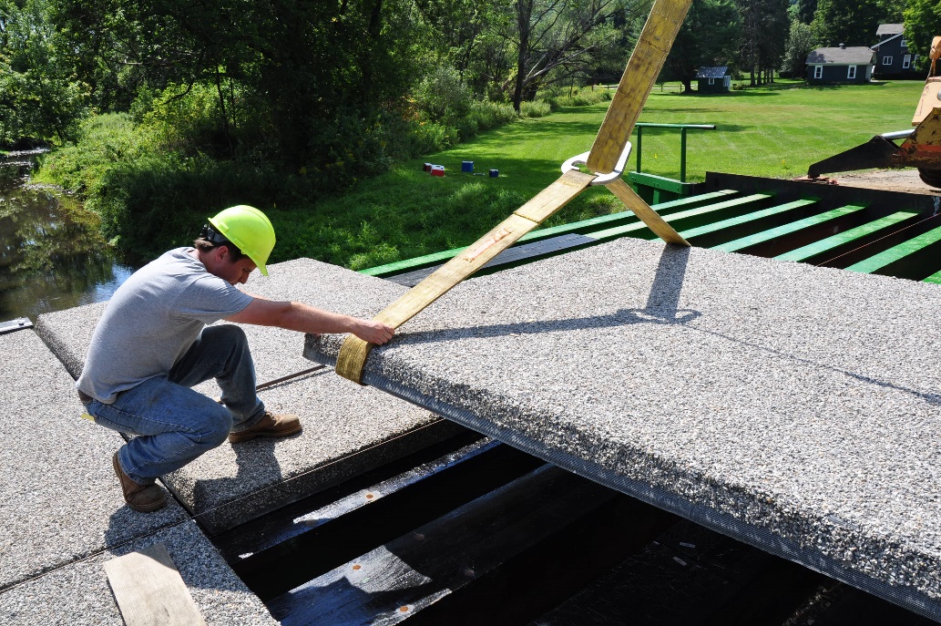
Need: Bridge owners expressed a need for a light-weight, solid-service deck. Solid-surface lightweight decks can alleviate weight restrictions on a bridge, save a historic bridge that has been compromised over time, or replace older light decks on bridges that cannot support a concrete one.
Technology: Composite materials such as fiber reinforced polymer (FRP) are ideal for bridge decks because of their high strength to weight ratio and resistance to corrosion.
Activities funded: Refinement of the materials and fabrication methods used to produce a FRP composite bridge deck developed by the University at Buffalo for New York State Department of Transportation and a demonstration installation in Allegany County, NY.
Further Information: https://www.fhwa.dot.gov/hfl/partnerships/bridgetech.cfm
Contact:
Amit Armstrong, Ph.D., P.E.
Program Manager
(503) 936-5414
amit.armstrong@dot.gov

