U.S. Department of Transportation
Federal Highway Administration
1200 New Jersey Avenue, SE
Washington, DC 20590
202-366-4000
Federal Highway Administration Research and Technology
Coordinating, Developing, and Delivering Highway Transportation Innovations
 |
| This report is an archived publication and may contain dated technical, contact, and link information |
|
Publication Number: FHWA-HRT-05-056
Date: October 2006 |
|||||||||||||||||||||||||||||||||||||||||||||||||||||||||||||||||||||||||||||||||||||||||||||||||||||||||||||||||||||||||||||||||||||||||||||||||||||||||||||||
|
Previous | Table of Contents | Next Chapter 3. COMPILATION OF INFORMATION AND SPECIFICATIONS FROM HPC BRIDGESACTION: Revisions to the maximum usable strain and the Φ factor are proposed.8.16.3 Flexure8.16.3.2 Rectangular Sections With Tension Reinforcement Only8.16.3.3 Flanged Sections With Tension Reinforcement Only8.16.3.4 Rectangular Sections With Compression Reinforcement OnlyThese three articles provide equations for the calculation of design moment strength and balanced reinforcement ratio based on a rectangular stress block and an assumed limiting concrete strain of 0.003. If the rectangular stress block and the limiting strains are not appropriate for HSC, the equations will need to be revised or their application restricted to lower concrete strengths. ACTION: None. Further research is the objective of NCHRP project 12-64. 8.16.4 Compression Members8.16.4.1 General Requirements8.16.4.1.2 Members subject to compressive axial load combined with
bending shall be designed for the maximum moment that can accompany
the axial load. The factored axial load, Pu, at a given
eccentricity shall not exceed the design axial load strength
f (a) For members with spiral reinforcement conforming to Article 8.18.2.2
(b) For members with tie reinforcement conforming to Article 8.18.2.3
The maximum factored moment, Mu, shall be magnified for slenderness effects in accordance with Article 8.16.5. HSC has less lateral expansion than conventional strength concrete, so the confinement effect is less. This affects column behavior. The constants used in equations 8-29 and 8-30 need to be evaluated for use with HSC. ACTION: None. Further research is the objective of NCHRP project 12-64. 8.16.4.2 Compression Member Strengths8.16.4.2.1 Pure Compression The design axial load strength at zero eccentricity,
For design, pure compressive strength is a hypothetical condition since Article 8.16.4.1.2 limits the axial load strength of compression members to 85 and 80 percent of the axial load at zero eccentricity. See comments on articles 8.16.2.7 and 8.16.4.1.2. ACTION: None. Further research is the objective of NCHRP project 12-64. 8.16.6 Shear8.16.6.2 Shear Strength Provided by Concrete8.16.6.2.1 Shear in Beams and One-Way Slabs and Footings For members subject to shear and flexure only, Vc shall be computed by,
or
where bw is the width of web and d is the distance from the extreme compression fiber to the centroid of the longitudinal tension reinforcement. Whenever applicable, effects of torsion shall be included. For a circular section, bw shall be the diameter and d need not be less than the distance from the extreme compression fiber to the centroid of the longitudinal reinforcement in the opposite half of the member. For tapered webs, bw shall be the average width or 1.2 times the minimum width, whichever is smaller. Note: (a) Vc shall not exceed 3.5 (b) The quality Vud/Mu shall not be greater than 1.0 where Mu is the factored moment occurring simultaneously with Vu at the section being considered. At higher compressive strengths, HSC is more brittle and the shear
cracks are smoother. As a result, there is less friction along the
shear cracks. Since this friction carries some of the shear load, shear provided by the concrete may be less. Consequently, the
constants used in the equations need to be investigated. The ACI
Building Code Requirements for Structural Concrete (ACI 318-99)
limits the term ACTION: None. Further research is being conducted under NCHRP project 12-56. 8.16.6.2.2 Shear in Compression Members For members subject to axial compression, Vc may be computed by:
or
Note: The quantity Nu /Ag shall be expressed in pounds per square inch. See comments on 8.16.6.2.1. ACTION: A research problem statement is proposed. 8.16.6.2.3 Shear in Tension Members For members subject to axial tension, shear reinforcement shall be designed to carry total shear, unless a more detailed calculation is made using:
Note: (a) Nu is negative for tension. (b) The quantity Nu /Ag shall be expressed in pounds per square inch. In equation 8-52, vc should be Vc. See comments on 8.16.6.2.1. ACTION: A research problem statement is proposed. 8.16.6.2.4 Shear in Lightweight Concrete The provisions for shear stress, vc, carried by the concrete, apply to normal-weight concrete. When lightweight aggregate concretes are used, one of the following modifications shall apply: (a) When fct is specified, the shear strength, Vc, shall be modified by substituting fct
/6.7 for (b) When fct is not specified, Vc shall be multiplied by 0.75 for all-lightweight concrete, and 0.85 for sand-lightweight concrete. Linear interpolation may be used when partial sand replacement is used. HPC can be all-lightweight or sand-lightweight concrete. The constants used in the article need to be evaluated for lightweight and sand-lightweight HPC. ACTION: A research problem statement is proposed. 8.16.6.3 Shear Strength Provided by Shear Reinforcement8.16.6.3.8 When shear strength Vs exceeds
4 There is a need to verify spacing requirements for HSC. ACTION: None. Further research is being conducted under NCHRP project 12-56. 8.16.6.3.9 Shear strength Vs shall not be taken great
than 8 The upper limit for Vs needs to be verified for HSC. The AASHTO LRFD Specifications allow a substantially higher value for the maximum shear strength. ACTION: None. Further research is being conducted under NCHRP project 12-56. 8.16.6.4 Shear Friction8.16.6.4.4 Shear-Friction Design Method (a) When the shear-friction reinforcement is perpendicular to the shear plane, shear strength Vn shall be computed by:
where (b) When the shear-friction reinforcement is inclined to the shear plane, such that the shear force produces tension in shear-friction reinforcement, shear strength Vn shall be computed by:
where af is the angle between the shear-friction reinforcement and shear plane. Coefficient of friction Concrete placed
monolithically.......................................................................
1.4 Concrete placed against hardened concrete with surface
intentionally roughened as specified in Article
8.16.6.4.8.........................................................................................................
1.0 Concrete placed against hardened concrete not intentionally
roughened..... 0.6 Concrete anchored to as-rolled structural steel by headed studs or
by reinforcing bars (see Article
8.16.6.4.9).........................................................................................................................
0.7 where Tests have indicated that a smoother crack plane occurs with
HSC.(15) Consequently, the values of ACTION: A research problem statement is proposed. 8.16.6.4.5 Shear strength Vn shall not be taken greater
than 0.2 This article imposes a limit of 28 MPa (4000 psi) on the compressive strength of concrete that can be used in design and is a barrier to the effective use of HSC. The limits of 0.2 ACTION: A research problem statement is proposed. 8.16.6.5 Horizontal Shear Strength for Composite Concrete Flexural Members8.16.6.5.3 Design of cross sections subject to horizontal shear may be based on:
where Vu is the factored shear force at the section considered, Vnh is the nominal horizontal shear strength in accordance with the following, and d is for the entire composite section.
The horizontal shear resistance needs to be evaluated for HPC. ACTION: A research problem statement is proposed. 8.16.6.6 Special Provisions for Slabs and Footings8.16.6.6.2 Design of slab or footing for two-way action shall be based on Equation (8-46), where shear strength Vn shall not be taken greater than shear strength Vc given by Equation (8‑58), unless shear reinforcement is provided in accordance with Article 8.16.6.6.3.
The constants used in equation 8-58 need to be verified for HSC. ACTION: A research problem statement is proposed. 8.16.6.6.3 Shear reinforcement consisting of bars or wires may be used in slabs and footings in accordance with the following provisions:
The limiting values of Vn and Vc need to be verified for HSC. ACTION: A research problem statement is proposed. 8.16.6.7 Special Provisions for Slabs of Box Culverts8.16.6.7.1 For slabs of box culverts under 2 feet or more fill, shear strength Vc may be computed by:
but Vc shall not exceed 4 Although HSC may not be used in slabs of box culverts, the constants in equation 8-59 and the limiting values of Vc should be verified. ACTION: A research problem statement is proposed. 8.16.6.8 Special Provisions for Brackets and Corbels*8.16.6.8.3 The section at the face of the support shall be designed to resist simultaneously a shear Vu, a moment (Vuav + Nuc (h – d)), and a horizontal tensile force Nuc. Distance h shall be measured at the face of support.
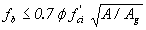
*These provisions do not apply to beam ledges. The PCA publication, “Notes on ACI 318-83, ” contains an example design of beam ledges, Part 16, example 16-3. Article (b) imposes a limit of 28 MPa (4000 psi) on the compressive strength of concrete that can be used in design and is a barrier to the effective use of HSC. The limits and factors need to be evaluated. ACTION: A research problem statement is proposed. 8.16.7 Bearing Strength8.16.7.1 The bearing stress, fb, on concrete
shall not exceed 0.85N 8.16.7.2 When the supporting surface is wider on all sides
than the loaded area, the allowable bearing stress on the loaded
area may be multiplied by 8.16.7.3 When the supporting surface is sloped or stepped, A2 may be taken as the area of the lower base of the largest frustum of a right pyramid or cone contained wholly within the support and having for its upper base the loaded area, and having side slopes of 1 vertical to 2 horizontal. 8.16.7.4 When the loaded area is subjected to high edge stresses due to deflection or eccentric loading, the allowable bearing stress on the loaded area, including any increase due to the supporting surface being larger than the loaded area, shall be multiplied by a factor of 0.75. The upper limit for the bearing stress, fb, needs to be verified for HSC. ACTION: A research problem statement is proposed. 8.17 Reinforcement of Flexural Members8.17.1 Minimum Reinforcement8.17.1.1 At any section of a flexural member where tension reinforcement is required by analysis, the reinforcement provided shall be adequate to develop a moment at least 1.2 times the cracking moment calculated on the basis of the modulus of rupture for normal-weight concrete specified in Article 8.15.2.1.1.
The purpose of this article is to ensure that the section does not
go to its ultimate strength state as soon as it cracks. HSC is
known to have proportionately higher tensile strength than
conventional strength concrete. This means that the actual value of
Mcr is higher than that calculated using 7.5 ACTION: Revisions to article 8.15.2.1.1 are proposed. 8.18 reinforcement of compression members 8.18.2 Lateral Reinforcement8.18.2.2 SpiralsSpiral reinforcement for compression members shall conform to the following: 8.18.2.2.1 Spirals shall consist of evenly spaced continuous bar or
wire, with a minimum diameter of 8.18.2.2.2 The ratio of spiral reinforcement to total volume of
core,
where fy is the specified yield strength of spiral reinforcement, but not more than 60,000 psi. Spirals are less effective for confinement in HSC. Another formula is reported by ACI Committee 363 and should be considered.(15) In addition, the ratio of reinforcement required by equation 8-63 may be too high to be practical with HSC. The concept for providing spiral reinforcement to strengthen the core to offset the loss of strength when the concrete shell is lost may not be appropriate for HSC. ACTION: A research problem statement is proposed. 8.18.2.3 TiesTie reinforcement for compression members shall conform to the following: 8.18.2.3.1 All bars shall be enclosed by lateral ties which shall be at least No. 3 in size for longitudinal bars that are No. 10 or smaller, and at least No. 4 in size for No. 11, No. 14, No. 18, and bundled longitudinal bars. Deformed wire or welded wire fabric of equivalent area may be used instead of bars. 8.18.2.3.2 The spacing of ties shall not exceed the least dimension of the compression member or 12 inches. When two or more bars larger than No. 10 are bundled together, tie spacing shall be one-half that specified above. 8.18.2.3.3 Ties shall be located not more than half a tie spacing from the face of a footing or from the nearest longitudinal reinforcement of a cross-framing member. 8.18.2.3.4 No longitudinal bar shall be more than 2 feet, measured along the tie, from a restrained bar on either side. A restrained bar is one which has lateral support provided by the corner of a tie having an included angle of not more than 135 degrees. Where longitudinal bars are located around the perimeter of a circle, a complete circular tie may be used. Since ties may be less effective with HSC, these provisions need to be evaluated. ACTION: A research problem statement is proposed. 8.19 Llimits for Shear Reinforcement8.19.1 Minimum Shear Reinforcement8.19.1.1 A minimum area of shear reinforcement shall be provided in all flexural members, except slabs and footings, where:
8.19.1.2 Where shear reinforcement is required by Article 8.19.1.1, or by analysis, the area provided shall not be less than:
where bw and s are in inches. The ACI 318 Building Code requires that the minimum area of shear reinforcement increase as concrete strength increases, but shall not be less than the value of Av calculated by equation 8‑64.(18) A similar modification to equation 8-64 should be considered. ACTION: A revision for minimum reinforcement is proposed. 8.22 protection against corrosion 8.22.1 The following minimum concrete cover shall be provided for reinforcement:
HPC is less permeable than conventional concrete, and offers the possibility of reducing the minimum concrete cover. The advantages and disadvantages of reducing the minimum cover with HPC should be evaluated. ACTION: None. 8.25 DEVELOPMENT OF DEFORMED BARS AND DEFORMED WIRE IN TENSION The development length, ld, in inches shall be computed as the product of the basic development length defined in Article 8.25.1 and the applicable modification factor or factors defined in Article 8.25.2 and 8.25.3, but ld shall be not less than that specified in Article 8.25.4. 8.25.1 The basic development length shall be:
The ACI 318 Building Code limits the value of ACTION: None. Further research is the objective of NCHRP project 12-60. 8.25.2 The basic development length shall be multiplied by the following applicable factor or factors: 8.25.2.1 Top reinforcement so placed that more than 12 inches of concrete is cast below the reinforcement........................................................................................................... 1.4 8.25.2.2 Lightweight aggregate concrete when fct
is specified............................. but not less than 1.0. When fct is not specified all-lightweight concrete...............................................................................................1.33 sand-lightweight concrete............................................................................................ 1.18 Linear interpolation may be applied when partial sand replacement is used. 8.25.2.3 Bars coated with epoxy with cover less than 3db or clear spacing between bars less than 6 db.................................................................................................................. 1.5 all other cases ..............................................................................................................1.15 The product obtained when combining the factor for top reinforcement with the applicable factor for epoxy-coated reinforcement need not be taken greater than 1.7. 8.25.3 The basic development length, modified by the appropriate factors of Article 8.25.2, may be multiplied by the following factors when: 8.25.3.1 Reinforcement being developed in the length under consideration is spaced laterally at least 6 inches on center with at least 3 inches clear cover measured in the direction of the spacing..............................................................0.8 8.25.3.2 Anchorage or development for reinforcement strength is not specifically required or reinforcement in flexural members is in excess of that required by analysis (As required)/(As provided) 8.25.3.3 Reinforcement is enclosed within a spiral of not less than 1/4 inch in diameter and not more than 4-inch pitch 0.75 8.25.4 The development length, ld, shall not be less than 12 inches except in the computation of lap splices by Article 8.32.3 and development of shear reinforcement by Article 8.27. The factors need to be verified for HPC. ACTION: None. Further research is the objective of NCHRP project 12-60. 8.26 DEVELOPMENT OF DEFORMED BARS IN COMPRESSION The development length, ld, in inches, for deformed bars in compression shall be computed as the product of the basic development length of Article 8.26.1 and applicable modification factors of 8.26.2, but ld shall not be less than 8 inches. 8.26.1 The basic development length shall be
........................................... 0.02
dbfy / but not less than...................................................................................0.0003 dbfy 8.26.2 The basic development length may be multiplied by applicable factors when: 8.26.2.1 Anchorage or development for reinforcement strength is not specifically required, or reinforcement is in excess of that required by analysis............................................. (As required)/(As provided) 8.26.2.2 Reinforcement is enclosed in a spiral of not less than 1/4 inch in diameter and not more than 4-inch pitch............... 0.75 The factors need to be verified for HPC. ACTION: None. Further research is the objective of NCHRP project 12-60. 8.28 DEVELOPMENT OF BUNDLED BARS The development length of individual bars within a bundle, in tension or compression, shall be that for the individual bar, increased by 20 percent for a three-bar bundle, and 33 percent for a four-bar bundle. The factors need to be verified for HPC. ACTION: None. Further research is the objective of NCHRP project 12-60. 8.29 DEVELOPMENT OF STANDARD HOOKS IN TENSION 8.29.1 Development length ldh in inches, for deformed bars in tension terminating in a standard hook (Article 8.23.1) shall be computed as the product of the basic development length lhb of Article 8.29.2 and the applicable modification factor or factors of Article 8.29.3, but ldh shall not be less than 8db or 6 inches, whichever is greater. 8.29.2 Basic development length lhb for a hooked bar with fy equal to 60,000 psi shall be ............................................................................................. 1,200 db / 
8.29.3 Basic development length lhb shall be multiplied by applicable modification factor or factors for: 8.29.3.1 Bar yield strength: Bars with fy other than 60,000 psi....................................................................... fy /60,000 8.29.3.2 Concrete cover: For No. 11 bar and smaller, side cover (normal to plane of hook) not less than 2½ inches, and for 90-deg hook, cover on bar extension beyond hook not less than 2 inches.......................................... 0.7 8.29.3.3 Ties or stirrups: For No. 11 bar and smaller, hook enclosed vertically or horizontally within ties or stirrup-ties spaced along the full development length ldh not greater than 3db, where db is diameter of hooked bar....... 0.8 8.29.3.4 Excess reinforcement: Where anchorage or development for fy is not specifically required, reinforcement in excess of that required by analysis...................... (As required)/(As provided) 8.29.3.5 Lightweight aggregate concrete...................................................................... 1.3 8.29.4 For bars being developed by a standard hook at discontinuous ends of members with both side cover and top (or bottom) cover over hook less than 2½ inches, hooked bar shall be enclosed within ties or stirrups spaced along the full development length ldh, not greater than 3 db, where db is the diameter of the hooked bar. For this case, the factor of Article 8.29.3.3 shall not apply. 8.29.5 Hooks shall not be considered effective in developing bars in compression. All the provisions of article 8.29 need to be verified for HPC. ACTION: None. Further research is the objective of NCHRP project 12-60. 8.30 DEVELOPMENT OF WELDED WIRE FABRIC IN TENSION 8.30.1 Deformed Wire Fabric8.30.1.1 The development length, ld, in inches of welded deformed wire fabric measured from the point of critical section to the end of wire shall be computed as the product of the basic development length of Article 8.30.1.2 or 8.30.1.3 and the applicable modification factor or factors of Articles 8.25.2 and 8.25.3, but ld shall not be less than 8 inches except in computation of lap splices by Article 8.32.5 and development of shear reinforcement by Article 8.27. 8.30.1.2 The basic development length of welded deformed wire fabric, with at least one cross wire within the development length not less than 2 inches from the point of critical section, shall be:
but not less than
*The units for 20,000 are psi. 8.30.1.3 The basic development length of welded deformed wire fabric, with no cross wires within the development length, shall be determined as for deformed wire in accordance with Article 8.25. 8.30.2 Smooth Wire FabricThe yield strength of welded smooth wire fabric shall be considered developed by embedment of two cross wires, with the closer cross wire not less than 2 inches from the point of critical section. However, development length ld measured from the point of critical section to outermost cross wire shall not be less than:
modified by (As required)/(As provided) for reinforcement in excess of that required by analysis and by factor of Article 8.25.2 for lightweight aggregate concrete, but ld shall not be less than 6 inches except in computation of lap splices by Article 8.32.6. All the provisions of article 8.30 need to be verified for HPC. ACTION: None. Further research is the objective of NCHRP project 12-60. 8.32 SPLICES OF REINFORCEMENT 8.32.1 Lap Splices8.32.1.1 Lap splices shall not be used for bars larger than No. 11, except as provided in Articles 8.32.4.1 and 4.4.11.4.1 8.32.1.2 Lap splices of bundled bars shall be based on the lap splice length required for individual bars within a bundle. The length of lap, as prescribed in Article 8.32.3 or 8.32.4 shall be increased 20 percent for a three-bar bundle and 33 percent for a four-bar bundle. Individual bar splices within the bundle shall not overlap. 8.32.1.3 Bars spliced by noncontact lap splices in flexural members shall not be spaced transversely farther apart than 1/5 the required length of lap or 6 inches. The above provisions of article 8.32.1 need to be verified for HPC. ACTION: None. Further research is the objective of NCHRP project 12-60. 8.32.3 Splices of Deformed Bars and Deformed Wire in Tension8.32.3.1 The minimum length of lap for tension lap splices
shall be as required for Class A, B, Class A splice......................................................................................... 1.0 ld Class B splice......................................................................................... 1.3 ld Class C splice........................................................................................ 1.7 ld 8.32.3.2 Lap splices of deformed bars and deformed wire in tension shall conform to table 8.32.3.2 Table 8.32.3.2. Tension lap splices.
*Ratio of area reinforcement provided to area of reinforcement required by analysis at splice location. The above provisions of article 8.32.3 need to be verified for HPC. ACTION: None. Further research is the objective of NCHRP project 12-60. Section 9: PRESTRESSED CONCRETE9.1 application 9.1.2 Notations
Since HSC is often specified at ages other than 28 days, consideration should be given to rewording this definition. ACTION: A revision to the notation is proposed. 9.2 concrete The specified compressive strength, Consideration should be given to including in this article since making and testing cylinders for needs to be addressed in division II, section 8, for HSC. ACTION: A revision to include 9.14 LOAD FACTORS The computed strength capacity shall not be less than the largest value from load factor design in Article 3.22. For the design of post-tensioned anchorage zones, a load factor of 1.2 shall be applied to the maximum tendon jacking force. The following strength capacity reduction factors shall be used: For factory-produced precast, prestressed concrete members, For post-tensioned cast-in-place concrete members, For shear, For anchorage zones, HSC is known to be more brittle than conventional strength concrete. Also, HPC requires much higher levels of quality control. Strength capacity reduction factors may need to be revised to reflect this. ACTION: A research problem statement is proposed. 9.15 Allowable Stresses The design of precast prestressed members ordinarily shall be based
on A survey by the Precast/Prestressed Concrete Institute indicates
that its members are consistently producing concrete members with ACTION: A revision to raise the limit to 70 MPa (10,000 psi) is proposed. 9.15.2 Concrete9.15.2.1 Temporary Stresses Before Losses Due to Creep and ShrinkageCompression: Pretensioned
members..................................................................................
0.60 Post-tensioned
members................................................................................
0.55 Tension: Precompressed tensile zone...................................No temporary allowable stresses are specified. See Article 9.15.2.2 for allowable stresses after losses. Other Areas: In tension areas with no bonded
reinforcement............................. 200 psi or 3 Where the calculated tensile stress exceeds this value, bonded
reinforcement shall be provided HSC is known to have a proportionally higher tensile strength. It may be possible to allow higher tensile stresses in HSC. ACTION: A research problem statement is proposed. 9.15.2.2 Stress at Service Load After Losses Have OccurredCompression:
Tension in the precompressed tensile zone:
Tension in other areas is limited by allowable temporary stresses specified in Article 9.15.2.1. HSC is known to have proportionally higher tensile strength. It may be possible to allow higher tensile stresses in HSC. ACTION: A research problem statement is proposed. 9.15.2.3 Cracking Stress*Modulus of rupture from tests or if not available: For normal-weight concrete..................................................................................7.5 For sand-lightweight
concrete..............................................................................6.3 For all other lightweight
concrete........................................................................5.5 HSC is known to have proportionally higher tensile strength. It may be possible to allow higher tensile stresses in HSC. ACTION: A revision for normal-weight concrete is proposed. A research problem statement is proposed for other weights of concrete. 9.15.2.4 Anchorage Bearing StressPost-tensioned anchorage at service load........................................................... 3,000 psi This limit is clearly intended for conventional strength concrete. A higher limit for HSC may be justified. ACTION: A research problem statement is proposed. 9.16 Loss of Prestress 9.16.2 Prestress Losses9.16.2.1 GeneralLoss of prestress due to all causes, excluding friction, may be determined by the following method.* The method is based on normal-weight concrete and one of the following types of prestressing steel: 250 or 270 ksi, seven-wire, stress-relieved or low-relaxation strand; 240 ksi stress-relieved wires; or 145 to 160 ksi smooth or deformed bars. Refer to documented tests for data regarding the properties and the effects of lightweight aggregate concrete on prestress losses. TOTAL LOSS
where
Equations are then provided for calculation of individual components of prestress losses. ACTION: Proposed revisions to the AASHTO LRFD Specifications for calculations of prestress losses have been developed in NCHRP project 18-07. A revision to adopt the same method in the AASHTO Standard Specifications is proposed. 9.16.2.2 Estimated LossesIn lieu of the preceding method, the following estimates of total losses may be used for prestressed members or structures of the usual design. These loss values are based on use of normal-weight concrete, normal prestress levels, and average exposure conditions. For exceptionally long spans, or for unusual designs, the method in Article 9.16.2.1 or a more exact method shall be used. Table 9.16.2.2. Estimate of prestress losses.
1 Losses due to friction are excluded. Friction losses should be computed according to Article 9.16.1. Recent research has indicated that these articles, developed for calculating prestress losses in conventional strength concretes, may not always provide reliable estimates for HSC bridge girders. For this reason, NCHRP project 18-07 was initiated with the objective of developing design guidelines for estimating prestress losses in pretensioned HSC bridge girders. Table 9.16.2.2 needs to be extended to include higher concrete strengths if this is feasible. Results of the NCHRP project will need to be incorporated into this article. ACTION: Proposed revisions to the AASHTO LRFD Specifications for calculations of prestress losses have been developed in NCHRP project 18-07. A revision to adopt the same method in the AASHTO Standard Specifications is proposed. 9.17 Flexural Strength 9.17.2 Rectangular Sections9.17.3 Flanged SectionsThese two articles provide equations for calculation of design flexural strength based on a rectangular stress block. If the rectangular stress block is not appropriate for HSC, the equations will need to be revised or their application restricted to conventional strength concretes. ACTION: None. Further research is the objective of NCHRP project 12-64. 9.18 DUCTILITY LIMITS 9.18.1 Maximum Prestressing SteelPrestressed concrete members shall be designed so that the steel is yielding as ultimate capacity is approached. In general, the reinforcement index shall be such that
and
does not exceed For members with reinforcement indices greater than For rectangular sections:
For flanged sections:
Unreinforced HSC is more brittle than conventional strength concrete. The equivalent rectangular stress block may require adjustment to reflect the brittleness. This, in turn, would result in a more realistic maximum limit for flexural reinforcement. Equations 9-22 and 9-23 imply that over-reinforced cross sections are allowed in prestressed concrete flexural members, whereas they are prohibited in non-prestressed flexural members. In prestressed concrete members, some sections away from the maximum moment sections may have the same amount of reinforcement as that at the maximum moment section, but with a smaller effective depth and thus a larger steel area index. Since these sections are non-critical sections, they are allowed provided equations 9-22 and 9-23 are used to calculate the moment strength. Other alternative rational approaches should be considered to eliminate the need for a maximum reinforcement index and strength equations for over-reinforced sections. ACTION: None. Further research is the objective of NCHRP project 12-64. 9.18.2 Minimum Steel9.18.2.1 The total amount of prestressed and nonprestressed
reinforcement shall be adequate to develop an ultimate moment at
the critical section at least 1.2 times the cracking moment
where
Appropriate values for Md/nc and Sbshall be used for any intermediate composite sections. Where beams are designed to be noncomposite, substitute Sb for Sc in the above equation for the calculation of M*cr . The purpose of this article is to ensure that the section does not
go to the ultimate strength state as soon as it cracks. HSC is
known to have proportionally higher tensile strength than
conventional strength concrete. This means that the actual value of
Mcr would be higher than that calculated using 7.5 ACTION: Revisions to article 9.15.2.3 are proposed. 9.18.2.2 The minimum amount of non-prestressed longitudinal reinforcement provided in the cast-in-place portion of slabs utilizing precast, prestressed deck panels shall be 0.25 square inch per foot of slab width. The purpose of this reinforcement is to help distribute wheel loads in the longitudinal direction when precast deck panels are not connected for longitudinal continuity. The appropriateness of requiring a fixed amount of reinforcement that is independent of concrete strength and the bending strength of the system should be evaluated. ACTION: A research problem statement is proposed. 9.20 shear 9.20.2 Shear–Strength Provided by Concrete9.20.2.1 The shear strength provided by concrete, Vc, shall be taken as the lesser of the values Vci or Vcw. 9.20.2.2 The shear strength, Vci, shall be computed by:
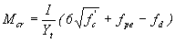
but need not be less than 1.7 The moment causing flexural cracking at the section due to external applied loads, Mcr, shall be computed by:
The maximum factored moment and factored shear at the section due to externally applied loads, Mmax and Vi, shall be computed from the load combination causing maximum moment at the section. 9.20.2.3 The shear strength, Vcw, shall be computed by:
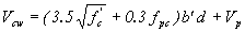
but d need not be taken less than 0.8h. 9.20.2.4 For a pretensioned member in which the section at a distance h/2 from the face of support is closer to the end of the member than the transfer length of the prestressing tendons, the reduced prestress shall be considered when computing Vcw. The prestress force may be assumed to vary linearly from zero at the end of the tendon to a maximum at a distance from the end of the tendon equal to the transfer length, assumed to be 50 diameters for strand and 100 diameters for single wire. 9.20.2.5 The provisions for computing the shear strength provided by concrete, Vci and Vcw, apply to normal-weight concrete. When lightweight aggregate concretes are used (see definition, concrete, structural lightweight, Article 8.1.3), one of the following modifications shall apply: (a) When fct is specified, the shear strength, Vci and Vcw, shall be modified by
substituting fct /6.7 for (b) When fct is not specified, Vci and
Vcw shall be modified by multiplying each term
containing At higher compressive strengths, HSC is more brittle and shear cracks are smoother. As a result, there is less friction along the shear cracks and the concrete contribution to shear may be less. Consequently, the constants used in the equations need to be investigated. The above article specifies a transfer length of 50 diameters for strands, whereas, the AASHTO LRFD Specifications specifies 60 diameters. Research data from the FHWA showcase bridges and FHWA research can be used to determine the appropriate number that will include HSC.(30) This is particularly important for 15.2-mm- (0.6-inch-) diameter strands used in most HSC beams. ACTION: None. Further research is being conducted under NCHRP project 12-56. 9.20.3 Shear Strength Provided by Web Reinforcement9.20.3.3 The minimum area of web reinforcement shall be:
where b’ and s are in inches and fsy is in psi. The ACI 318 Building Code requires that the minimum area of shear reinforcement increase as concrete strength increases, but shall not be less than the value of Av calculated by equation 9‑31.(18) A similar modification to equation 9-31 should be considered. ACTION: A revision for minimum reinforcement is proposed. 9.20.3.4 The design yield strength of web reinforcement, fsy, shall not exceed 60,000 psi. The use of a design yield strength higher than 414 MPa (60,000 psi) should be considered for both HSC and conventional concrete. ACTION: A revision to allow higher design yield strengths is proposed. 9.21 POST-TENSIONED ANCHORAGE ZONES 9.21.7 Design of the Local Zone9.21.7.2 Bearing Strength9.21.7.2.1 Anchorage devices may be either basic anchorage devices meeting the bearing compressive strength limits of Articles 9.21.7.2.2 through 9.21.7.2.4 or special anchorage devices meeting the requirements of section 9.21.7.3. 9.21.7.2.2 The effective concrete-bearing compressive strength used for design shall not exceed that of Equations (9-39) or (9-40).
but
where
Equations (9-39) and (9-40) are only valid if general zone reinforcement satisfying Article 9.21.3.4 is provided and if the extent of the concrete along the tendon axis ahead of the anchorage device is at least twice the length of the local zone as defined in Article 9.21.7.1.3 HSC is proportionally stronger in tension than conventional
strength concrete (bearing failures are often splitting failures), but also more brittle. The suitability of the bearing equations
needs ACTION: A research problem statement is proposed. 9.23 CONCRETE STRENGTH AT STRESS TRANSFER Unless otherwise specified, stress shall not be transferred to concrete until the compressive strength of the concrete as indicated by test cylinders, cured by methods identical with the curing of the members, is at least 4,000 psi for pretensioned members (other than piles) and 3,500 psi for post-tensioned members and pretensioned piles. Since HSC generates more heat of hydration than conventional strength concrete, it is important that test cylinders be cured at the same temperature as the member. Enclosing the cylinders under the same cover as the member does not ensure this, particularly when external steam or heat curing is not used. This article needs to be revised to be more specific. ACTION: A revision referencing division II procedures is proposed. 9.26 COVER AND SPACING OF STEEL 9.26.1 Minimum CoverThe following minimum concrete cover shall be provided for prestressing and conventional steel: 9.26.1.1 Prestressing Steel and Main Reinforcement................................ 1½ inches 9.26.1.2 Slab Reinforcement 9.26.1.2.1 Top of
Slab................................................................................
1½ inches 9.26.1.2.2 Bottom of Slab................................................................................ 1 inch 9.26.1.3 Stirrups and Ties................................................................................ 1 inch 9.26.1.4 When deicer chemicals are used, drainage details shall dispose of deicer solutions without constant contact with the prestressed girders. Where such contact cannot be avoided, or in locations where members are exposed to salt water, salt spray, or chemical vapor, additional cover should be provided. HPC is usually more impermeable than conventional concrete and a longer service life is expected. ACTION: None. 9.28 EMBEDMENT OF PRESTRESSED STRAND 9.28.1 Three- or seven-wire pretensioning strand shall be bonded beyond the critical section for a development length in inches not less than
where D is the nominal diameter in inches, 9.28.3 Where strand is debonded at the end of a member and tension at service load is allowed in the precompressed tensile zone, the development length required above shall be doubled. Development lengths for the combination of 15.2-mm- (0.6-inch-) diameter strand used with HSC need to be evaluated based on FHWA and other research.(30) ACTION: None. Further research is the objective of NCHRP project 12-60. Section 17: SOIL-REINFORCED CONCRETE STRUCTURE INTERACTION SYSTEMS This section covers buried reinforced concrete structures such as pipes and culverts. However, any articles that include concrete materials, stresses, or design refer back to section 8. ACTION: None. Division II: ConstructionSection 8: CONCRETE STRUCTURES 8.2 CLASSES OF CONCRETE This article provides definitions for normal-weight and lightweight concrete. A definition of HPC may need to be added as a means of identifying when special provisions for HPC apply. ACTION: Revisions to add two classes of HPC are proposed. 8.3 MATERIALS 8.3.1 CementsPortland Cements shall conform to the requirements of AASHTO M 85 (ASTM C 150) and Blended Hydraulic Cements shall conform to the requirements of AASHTO M 240 (ASTM C 595). For Type IP portland-pozzolan cement, the pozzolan constituent shall not exceed 20 percent of the weight of the blend and the loss on ignition of the pozzolan shall not exceed 5 percent. Unless otherwise specified, only Types I, II, or III Portland Cement; Types IA, IIA, or IIIA Air-Entrained Portland Cement or Types IP or IS Blended Hydraulic Cements shall be used. Types IA, IIA, and IIIA cement may be used only in concrete where air entrainment is required. Low-alkali cements conforming to the requirements of AASHTO M 85 for low-alkali cement shall be used when specified or when ordered by the Engineer as a condition of use for aggregates of limited alkali-silica reactivity. Unless otherwise permitted, the product of only one mill of any one brand and type of cement shall be used for like elements of a structure that are exposed to view, except when cements must be blended for reduction of any excessive air entrainment where air-entraining cement is used. By definition, HPC is a concrete where certain properties have been modified to increase performance. Restricting the cement to types I, II, III, IA, IIA, IIIA, IP, or IS may prevent the designer from using different types of cement to enhance concrete performance. For example, the use of type IV cement reduces the heat of hydration in high cement content HPC, and type V provides higher sulfate resistance. Cements conforming to ASTM C 1157, Standard Performance Specification for Blended Hydraulic Cement, should be included. HPC is very sensitive to the brand, type, and mill of origin of the cement. Studies have shown that changing the brand of cement can cause great differences in the final hardened properties of HPC.(15) The final paragraph should be modified to include special restrictions for HPC. Consideration should be given to addressing interaction effects between cement components and mineral or chemical admixtures. ACTION: Revisions to add ASTM C 1157 and reference the two classes of HPC are proposed. 8.3.2 WaterMixing water for concrete in which steel is embedded shall not contain a chloride ion concentration in excess of 1,000 ppm or sulfates such as SO4 in excess of 1,300 ppm. These limits should be evaluated for use with HPC and prestressed concrete. ACTION: A research problem statement is proposed. 8.3.3 Fine AggregatesFine aggregate for concrete shall conform to the requirements of AASHTO M 6. The coarse and fine aggregates in HPC should be blended together to obtain the maximum density. This will increase strength, decrease permeability, and lower the required cementitious materials content. The requirements of AASHTO M 6 may be too broad for HPC. ACTION: A new specification for combined aggregates is proposed. 8.3.4 Coarse AggregateCoarse aggregate for concrete shall conform to the requirements of AASHTO M 80. The coarse and fine aggregates in HPC should be blended together to obtain the maximum density. This will increase strength, decrease permeability, and lower the required cementitious materials content. The requirements of AASHTO M 80 may be too broad for HPC. ACTION: A new specification for combined aggregates is proposed. 8.3.7 Mineral AdmixturesFly ash pozzolans and calcined natural pozzolans for use as mineral admixtures in concrete shall conform to AASHTO M 295 (ASTM C 618). The use of fly ash as produced by plants that utilize the limestone injection process or compounds of sodium, ammonium, or sulfur, such as soda ash, to control stack emissions shall not be used in concrete. A Certificate of Compliance, based on test results and signed by the producer of the mineral admixture certifying that the material conforms to the above specifications, shall be furnished for each shipment used in the work. This article should be modified to include other pozzolans and ground granulated blast-furnace slag (AASHTO M 307). Available research should also be checked to determine whether pozzolans from nontraditional sources, such as fly ash from petroleum coke or bark ash, can be used in HPC. ACTION: A revision to include other materials is proposed. 8.4 PROPORTIONING OF CONCRETE 8.4.1 Mix Design8.4.1.1 Responsibility and CriteriaThe contractor shall design and be responsible for the performance of all concrete mixes used in structures. The mix proportions selected shall produce concrete that is sufficiently workable and finishable for all uses intended and shall conform to the requirements in table 8.2 and all other requirements of this section. For normal-weight concrete, the absolute volume method, as described in American Concrete Institute Publication 211.1, shall be used in selecting the mix proportions. For structural lightweight concrete, the mix proportions shall be selected on the basis of trial mixes with the cement factor rather than the water/cement ratio being determined by the specified strength using methods such as those described in American Concrete Institute Publication 211.2. The mix design shall be based upon obtaining an average concrete strength sufficiently above the specified strength so that, considering the expected variability of the concrete and test procedures, no more than 1 in 10 strength tests will be expected to fall below the specified strength. Mix designs shall be modified during the course of the work when necessary to ensure compliance with strength and consistency requirements. HPC is often designed to have enhanced properties other than strength, thus a strength-based specification will not apply to many forms of HPC. This article should be modified to permit other properties to control the concrete mix design. Table 8.2 needs to be extended to incorporate values for HPC. This article requires the use of the absolute volume method for normal-weight concrete. For HPC and especially HSC, type, size, grading, and shape of aggregate require more attention than they do with conventional strength concrete mixtures. For HSC, a large amount and smaller nominal maximum size of coarse aggregate are generally required. HSC mixtures usually have a high cementitious materials content and a low water-cementitious materials ratio. For a given set of constituent materials, a decrease in the ratio results in an increase in compressive strength. However, when different materials are used, similar strengths can be achieved at different ratios. Consequently, HPC and HSC mix proportions should always be determined from trial batch tests. Finally, HPC is very sensitive to changes in the constitutive materials. The mix design of HPC should NOT be changed during the job unless tests show that the material is failing to meet specifications or there is a change in any constitutive material. If changes to the mix design are required, trial batch tests should be required. ACTION: Revisions to include the two classes of HPC are proposed. 8.4.1.2 Trial Batch TestsFor classes A, A(AE), and P concrete, for lightweight concrete, and for other classes of concrete when specified or ordered by the Engineer, satisfactory performance of the proposed mix design shall be verified by laboratory tests on trial batches. The results of such tests shall be furnished to the Engineer by the contractor or the manufacturer of the precast elements at the time the proposed mix design is submitted. For mix design approval, the strengths of a minimum of five test cylinders taken from a trial batch shall average at least 800 psi greater than the specified strength. If materials and a mix design identical to those proposed for use have been used on other work within the previous year, certified copies of concrete test results from this work that indicate full compliance with these specifications may be substituted for such laboratory tests. If the results of more than 10 such strength tests are available from historical records for the past year, the average strength for these tests shall be at least 1.28 standard deviations above the specified strength. HPC may be designed with an emphasis on properties other than strength. This article should be revised to allow acceptance of a mix based on properties other than strength. For HSC, the requirement that the average strength be 5.5 MPa (800 psi) above the average may be too low. For example, 5.5 MPa (800 psi) is 20 percent over strength for 28-MPa (4000-psi) concrete, 10 percent over strength for 55-MPa (8000-psi) concrete, but only 7 percent over strength for 83-MPa (12,000-psi) concrete. Consideration should be given to adopting the revisions from ACI Committee 318-02, which have different requirements for conventional and high-strength concrete.(18) ACTION: Revisions to the over-strength requirement are proposed. 8.4.3 Cement ContentThe minimum cement content shall be as listed in table 8.2 or otherwise specified. The maximum cement or cement plus mineral admixture content shall not exceed 800 pounds per cubic yard of concrete. The actual cement content used shall be within these limits and shall be sufficient to produce concrete of the required strength and consistency. HPC for use in massive bridge foundations may require less cement than the values indicated in table 8.2 to reduce the heat of hydration. HSC often requires a total cementitious materials content greater than 475 kg/m3 (800 lb/yd3). Often, a maximum of 593 kg/m3 (1000 lb/yd3) is used as the limit in HSC. Revisions to this provision are required to accommodate HPC. Also, the cement content affects properties such as creep, shrinkage, permeability, etc. The last sentence should be modified to include a broader range of properties. ACTION: A revision to increase the maximum cementitious materials content for HPC is proposed. 8.4.4 Mineral AdmixturesMineral admixtures shall be used in the amounts specified. In addition, when either Types I, II, IV, or V (AASHTO M 85) cements are used and mineral admixtures are neither specified nor prohibited, the Contractor will be permitted to replace up to 20 percent of the required Portland cement with a mineral admixture. The weight of the mineral admixture used shall be equal to or greater than the weight of the Portland cement replaced. In calculating the water/cement ratio of the mix, the weight of the cement shall be considered to be the sum of the weights of the Portland cement and the mineral admixture. HPC is very sensitive to the constitutive materials. Adding mineral admixtures when they are not specifically called for can adversely affect the concrete properties. This article should prohibit the use of mineral admixtures in HPC unless they are specified in the mix design or should require additional trial mixes whenever changes in the mix proportions are proposed. In addition, the maximum replacement percentage needs to be higher when fly ash and ground granulated blast-furnace slag are used and lower for silica fume. For HPC, it is more appropriate to consider total cementitious materials content and water-cementitious materials ratio rather than cement replacement. Changes in the wording should be considered. ACTION: Revisions to permit larger percentages and other cementitious materials are proposed. 8.5 Manufacture of Concrete 8.5.4 Batching and Mixing Concrete8.5.4.2 MixingThe minimum drum revolutions for transit mixers at the mixing speed recommended by the manufacturer shall not be less than 70 and not less than that recommended by the manufacturer. For HPC, a larger number of revolutions than 70 may be needed to ensure proper mixing of all constituent materials. ACTION: None. 8.5.7 Evaluation of Concrete Strength8.5.7.1 TestsA strength test shall consist of the average strength of two compressive strength test cylinders fabricated from material taken from a single randomly selected batch of concrete, except that if any cylinder should show evidence of improper sampling, molding, or testing, said cylinder shall be discarded and the strength test shall consist of the strength of the remaining cylinder. ACI Committee 363 recommends three specimens for each strength test for HSC.(16) Consideration should be given to revising this provision. ACTION: A revision to require three specimens for HSC is proposed. 8.5.7.2 For Controlling Construction OperationsFor determining adequacy of cure and protection, and for determining when loads or stresses can be applied to concrete structures, test cylinders shall be cured at the structure site under conditions that are not more favorable than the most unfavorable conditions for the portions of the structure that they represent as described in Article 9.4 of AASHTO T 23. Sufficient test cylinders shall be made and tested at the appropriate ages to determine when operations such as release of falsework, application of prestressing forces, or placing the structure in service can occur. Curing specimens according to the most unfavorable conditions may not be appropriate for high-strength precast, prestressed concrete. A lower temperature for the cylinder will produce a lower compressive strength for the cylinder at release age than is achieved by higher temperatures in the precast member. However, this can result in the cylinder having a higher strength than that of the precast member at later ages. The use of the match-curing technique should be considered for precast, prestressed concrete. Generally, this requires the use of 102- by 203-mm (4- by 8-inch) cylinders. The use of 102- by 203-mm (4- by 8-inch) cylinders should be evaluated. In addition, specifications should be developed for the match-curing system. ACTION: Revisions to section 8.5.7.5 are proposed. 8.5.7.3 For Acceptance of ConcreteFor determining compliance of concrete with a specified 28-day strength, test cylinders shall be cured under controlled conditions as described in Article 9.3 of AASHTO T 23 and tested at the age of 28 days. Samples for acceptance tests for each class of concrete shall be taken not less than once a day nor less than once for each 150 cubic yards of concrete or once for each major placement. Any concrete represented by a test which indicates a strength which is less than the specified 28‑day compressive strength by more than 500 psi will be rejected and shall be removed and replaced with acceptable concrete. Such rejection shall prevail unless either:
HPC often contains pozzolans, which hydrate more slowly. In this case, requirements for testing at 28 days may not be appropriate. The rejection criteria of 3.5 MPa (500 psi) should be re-examined for HSC; 3.5 MPa (500 psi) is 13 percent of the strength for a 28-MPa (4000-psi) concrete, but only 5 percent of the strength for a 69-MPa (10,000-psi) mix. Since a premium price is often paid for HPC, consideration should be given to rejecting concrete that does not meet the specification. A reduced payment cannot compensate for a loss of durability and possible reduced service life. ACTION: Revisions to include the two classes of HPC are proposed. 8.5.7.5 Steam and Radiant Heat-Cured ConcreteWhen a precast concrete member is steam or radiant heat cured, the compressive strength test cylinders made for any of the above purposes shall be cured under conditions similar to the member. Such concrete will be considered to be acceptable whenever a test indicates that the concrete has reached the specified 28-day compressive strength provided such strength is reached not more than 28 days after the member is cast. Consideration needs to be given for strengths specified at ages other than 28 days and to the use of match-cured cylinders. For HPC, curing cylinders under similar conditions may not be sufficient. Match curing provides a more realistic condition. This, generally, requires the use of 102- by 203-mm (4- by 8-inch) cylinders. The use of 102- by 203-mm (4- by 8-inch) cylinders should be evaluated. In addition, specifications should be developed for the match-curing system. ACTION: Revisions to include match curing are proposed. 8.6 protection of concrete from environmental conditions 8.6.4 Cold Weather Protection8.6.4.1 Protection During CureWhen there is a probability of air temperatures below 35 °F during the cure period, the Contractor shall submit for approval by the Engineer prior to concrete placement, a cold weather concreting and curing plan detailing the methods and equipment which will be used to assure that the required concrete temperatures are maintained. The concrete shall be maintained at a temperature of not less than 45 °F for the first six days after placement, except when pozzolan cement or fly ash cement is used, this period shall be as follows:
The above requirement for an extended period of controlled temperature may be waived if a compressive strength of 65 percent of the specified 28-day design strength is achieved. This provision only addresses pozzolans. It needs to include other mineral admixtures and higher percentages. The above table requires a controlled temperature period of 8 days or until 65 percent of the specified strength is achieved when 10 percent pozzolans are used. Article 8.11.1 requires a curing period of 10 days or until 70 percent of the specified strength is achieved when pozzolans in excess of 10 percent are used. These two articles need to be consistent. In lieu of fixed periods of controlled temperature, the match-curing method or maturity method could be used. The potential for using these methods needs to be evaluated. ACTION: Revisions to include slag and higher percentages of cement replacement are proposed. 8.6.6 Concrete Exposed to Salt Water8.6.7 Concrete Exposed to Sulfate Soils or WaterThese two articles provide special considerations for concrete exposed to specific environmental conditions. These are ideal applications for HPC and the provisions need to be revised accordingly. ACTION: Revisions to require HPC are proposed. 8.11 CURING OF CONCRETE 8.11.1 GeneralAll newly placed concrete shall be cured so as to prevent the loss of water by use of one or more of the methods specified herein. Curing shall commence immediately after the free water has left the surface and finishing operations are completed. If the surface of the concrete begins to dry before the selected cure method can be applied, the surface shall be kept moist by a fog spray applied so as not to damage the surface. Curing by other than steam or radiant heat methods shall continue uninterrupted for 7 days except that when pozzolans in excess of 10 percent, by weight, of the Portland cement are used in the mix. When such pozzolans are used, the curing period shall be 10 days. For other than top slabs of structures serving as finished pavements, the above curing periods may be reduced and curing terminated when test cylinders cured under the same conditions as the structure indicate that concrete strengths of at least 70 percent of that specified have been reached. When deemed necessary by the Engineer during periods of hot weather, water shall be applied to concrete surfaces being cured by the liquid membrane method or by the forms-in-place method until the Engineer determines that a cooling effect is no longer required. Such application of water will be paid as extra work. HPC tends to have very little bleed water, especially when a low water-cementitious materials ratio is used with mineral admixtures. As a result, the evaporation protection of the bleed water on the fresh concrete is lost. To prevent plastic shrinkage cracking, this article should require methods to retard or prevent evaporation of bleed water from HPC during placement and finishing. The lack of bleed water makes the forms-in-place method (8.11.3.1), the liquid membrane curing compound method (8.11.3.3), and the waterproof cover method (8.11.3.4) of curing ineffective for HPC. Also, the low water-cementitious materials ratios in some HPC mixes make the addition of external water desirable. For HPC, only the water method (8.11.3.2) or steam curing (8.11.3.5) should be allowed. In addition, another article needs to be added for concrete that is heat cured from its own heat of hydration. This article specifies curing times and allows curing to be discontinued in certain members when the concrete achieves a compressive strength equal to 70 percent of the specified strength. This approach was developed for conventional concretes, but may not be appropriate for HPC. For HPC with low water-cementitious materials ratios, external water may be needed to keep the hydration process going. The curing times and percentages need to be evaluated for use with HPC. The curing period of 10 days or until 70 percent of the specified strength is reached needs to be consistent with the requirements of 8.6.4.1. HPC tends to have larger quantities of cement and, therefore, higher heat of hydration. The ACTION: Revisions to add curing procedures for HPC are proposed. 8.11.3 Methods8.11.3.3 Liquid Membrane Curing Compound MethodIf the solution is applied in two increments, the second application shall follow the first application within 30 minutes. The second application should be applied in a direction perpendicular to the direction of the first application. ACTION: None. 8.11.3.5 Steam or Radiant Heat Curing MethodThis method may be used only for precast concrete members manufactured in established plants. Steam curing or radiant heat curing shall be done under a suitable enclosure to contain the live steam or the heat. Steam shall be low pressure and saturated. Temperature recording devices shall be employed as necessary to verify that temperatures are uniform throughout the enclosure and are within the limits specified. Since HSC generates significantly more heat than conventional strength concrete, it is important that concrete temperatures be monitored rather than temperatures throughout the enclosure. Otherwise, the concrete temperatures could exceed 100 °C (212 °F), while the enclosure temperature is at 71 °C (160 °F). In addition, it may be desirable to specify a maximum internal concrete temperature and maximum temperature differentials. ACTION: Revisions to require measurement of concrete temperatures are proposed. Unless the ambient temperature is maintained above 60 °F, for prestressed members the transfer of the stressing force to the concrete shall be accomplished immediately after the steam curing or heat curing has been discontinued. A temperature of 16 °C (60 °F) may be too low for HSC. It would seem that transfer has to occur immediately for all ambient temperatures with HSC. ACTION: A revision to require immediate transfer is proposed. 8.11.4 Bridge DecksThe top surfaces of bridge decks shall be cured by a combination of the liquid membrane curing compound method and the water method. The liquid membrane shall be Type 2, white pigmented, and shall be applied from finishing bridges progressively and immediately after finishing operations are complete on each portion on the deck. The water cure shall be applied not later than 4 hours after completion of deck finishing or, for portions of the decks on which finishing is completed after normal working hours, the water cure shall be applied not later than the following morning. This article requires the use of both the liquid membrane method and the water methods for bridge decks. For HPC, it is essential that water cure begin as soon as the concrete finishing is complete and that the water be able to reach the concrete. Delaying the application of water until the following morning is not acceptable. This provision should also allow the use of membrane curing after the water-curing period. ACTION: A revision to require water curing with HPC is proposed. 8.13 Precast Concrete Members 8.13.4 CuringUnless otherwise permitted, precast members shall be cured by either the water method or the steam or radiant heat method. For HSC, there needs to be a method for curing by covering the members to retain heat and moisture, with or without the use of insulating blankets. ACTION: A revision to include the waterproof cover method is proposed. Previous | Table of Contents | Next FHWA-HRT-05-056 | |||||||||||||||||||||||||||||||||||||||||||||||||||||||||||||||||||||||||||||||||||||||||||||||||||||||||||||||||||||||||||||||||||||||||||||||||||||||||||||||


 is the coefficient of friction in accordance with Article
(c).
is the coefficient of friction in accordance with Article
(c).
 Acv nor 800 Acv in pounds, where Acv is area of the concrete section resisting
shear transfer.
Acv nor 800 Acv in pounds, where Acv is area of the concrete section resisting
shear transfer.
 c is the ratio of long side to short side of
concentrated load or reaction area, and bo is the
perimeter of the critical section defined in Article 8.16.6.6.1(b).
c is the ratio of long side to short side of
concentrated load or reaction area, and bo is the
perimeter of the critical section defined in Article 8.16.6.6.1(b).


 equal to or greater than 41 MPa (6000 psi).
The wording of this article needs to be revised to reflect the
current practice and remove a barrier to the use of HSC. This
limitation is also inconsistent with the limitation of 70 MPa
(10,000 psi) in the AASHTO LRFD Specifications.
equal to or greater than 41 MPa (6000 psi).
The wording of this article needs to be revised to reflect the
current practice and remove a barrier to the use of HSC. This
limitation is also inconsistent with the limitation of 70 MPa
(10,000 psi) in the AASHTO LRFD Specifications.


 for rectangular sections
 for flanged
sections
for flanged
sections 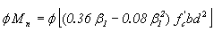


 and fse are in kips per square inch, and the parenthetical expression is considered to be without units.