- In this research, FRP dowels were found to be good alternatives to traditional steel dowels for transferring joint loads in JPCP pavements. Joints with FRP dowels provided adequate LTE, exceeding the values recommended by AASHTO (75 percent) and ACPA (60 percent) in both laboratory and field tests.
- FRP dowel-concrete interfaces in slabs number 1 and 4 were found to be in excellent condition after 5 million HS25 load cycles with no visible damage, microcracks, or separation between FRP dowels and surrounding concrete (refer to figure 36 and figure 44).
- The stiffness match between FRP dowels and concrete led to comparable FRP dowel flexing under joint loads, leading to shorter FRP dowel length. The required length of FRP dowels with 3.81-cm (1.5-inch) diameter was 64.7 percent of that for steel dowels with the same diameter. The required length of FRP dowels with a 2.54-cm (1.0-inch) diameter was
69.23 percent of that for steel dowels with the same diameter.
- Under the static loading test, slabs with smaller-diameter FRP dowels and smaller spacing provided lower RD than FRP dowels with larger diameter and spacing. During fatigue load cycles up to 5 million, RD from slab number 1 with the smaller diameter and spacing of FRP dowels appeared to increase (0.3256 to 2.0396 cm (0.0128 to 0.0803 inches) from 2 to
5 million cycles with a joint width of 1.016 cm (0.4 inches)), whereas RD from slab number 4 with a larger diameter and spacing of FRP dowels appeared to decrease 32 percent (0.0635 to 0.0432 cm (0.025 to 0.017 inches) from 2 to 5 million cycles with a joint width of
0.0635 cm (0.25 inches).
- The LTE from slabs with FRP dowels of smaller diameter and spacing (2.54 cm (1 inch) and 15.24 cm (6 inches)) was found to be sufficient (71.57 percent, when an increased joint width of 1.016 cm (0.4 inch) and higher loading of 1.5 × HS25 were considered) after 5 million load cycles as per AASHTO (70 percent of LTE) and ACPA (75 percent of E or 60 percent of LTE) suggested values. When a good base condition was provided during 5 million loading cycles, slabs with FRP dowels having 3.81-cm (1.5-inch) diameter and 30.48-cm (12-inch) spacing provided good LTE (greater than 80.5 percent). However, with a poor base condition (aggregate movement leading to a concave surface under the slab), the LTE was reduced to 55.26 percent (which is 92.1 percent of 60 percent LTE, corresponding to the ACPA recommended value on joint effectiveness, E = 75 percent). Hence, it is very important to have the proper slab casting procedure and compacted aggregate base.
- LTE affected the slab integrity and slab stresses, whereas RD affected ride comfort and impact on the slab at joints. It was important to consider both RD and LTE when the performance of JPCP was evaluated. For example, at 5 million cycles, slab number 4 with 3.81-cm (1.5-inch)-diameter FRP dowels spaced at 30.48 cm (12 inches) c/c had
55.26 percent LTE, but its RD (0.043 cm (0.017 inch)) was less than that of slab number 1 with 2.54-cm (1.0-inch)-diameter FRP dowels and 71.6 percent LTE spaced at 15.24 cm
(6 inches) c/c (2.04 cm (0.0803 inch)).
- FRP dowels can be used as effective alternatives for construction and rehabilitation of JPCP under highway traffic with advantages of corrosion resistance and decreased maintenance. Long-term performance evaluation of JPCP with FRP dowels is being continued by the Constructed Facilities Center, WVU.
- Test more laboratory specimens for establishing possible ranges of LTE and RD values for different diameter, spacing, and length of dowel.
- Further investigate crack formation location by using increased FRP dowel length, including deflection shapes.
- Evaluate actual dowel bar deflected shapes in the slab under different base removal conditions.
- Evaluate the effect of peak bearing stress and average bearing stress on dowel/concrete interface.
- Evaluate the effect of fiber volume fraction on dowel behavior, including shear properties that affect joint LTE and RD.
- Evaluate the durability of the FRP dowel.
- Utilize finite element modeling to envision stress field in the concrete pavement.
- Continue long-term field monitoring.
Before evaluating FRP dowels in concrete slabs joints, pilot tests were carried out using rectangular timber beams. A long timber beam was cut into two halves and drilled with 4.45-cm (1.75-inch)-diameter holes to simulate dowel sockets in a slab. Dowel sockets facilitated placement of instrumented dowels inside the timber beams. Load tests were conducted by turning dowels at 45-degree angles to measure dowel strains from longitudinal and transverse gauges (figure 110 to figure 112).
Four cases were evaluated based on loading position and timber depth (corresponding to positioning of the timber beam surface on the base). Test setup of each case is shown in
figure 111.
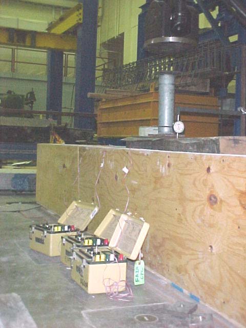
Figure 110. Photo. Lab test of timber tie with FRP dowel bar as the load transfer device.
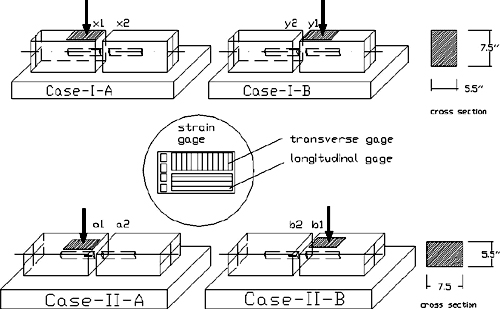
Figure 111. Diagram. Four timber test cases.
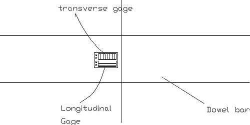
Figure 112. Diagram. Rosette strain gauges.
Table 40. Strains during loading and unloading on case I-A.
Loading |
|
Unloading |
Load (kips) |
Transverse Gauge |
Longitudinal Gauge |
Load (kips) |
Transverse Gauge |
Longitudinal Gauge |
0 |
0 |
0 |
20 |
1,627 |
7,836 |
1 |
64 |
576 |
19 |
1,610 |
7,797 |
2 |
229 |
1,707 |
18 |
1,580 |
7,752 |
3 |
377 |
2,585 |
17 |
1,554 |
7,707 |
4 |
493 |
3,182 |
16 |
1,527 |
7,662 |
5 |
624 |
3,848 |
15 |
1,498 |
7,609 |
6 |
725 |
4,389 |
14 |
1,467 |
7,562 |
7 |
804 |
4,770 |
13 |
1,432 |
7,522 |
8 |
871 |
5,118 |
12 |
1,391 |
7,420 |
9 |
933 |
5,415 |
11 |
1,346 |
7,365 |
10 |
1,021 |
5,668 |
10 |
1,292 |
7,167 |
11 |
1,105 |
5,962 |
9 |
1,226 |
7,032 |
12 |
1,166 |
6,188 |
8 |
1,135 |
6,982 |
13 |
1,223 |
6,384 |
7 |
1,032 |
6,670 |
14 |
1,285 |
6,584 |
6 |
940 |
6,495 |
15 |
1,347 |
6,844 |
5 |
790 |
5,957 |
16 |
1,393 |
7,011 |
4 |
674 |
5,610 |
17 |
1,451 |
7,204 |
3 |
560 |
4,971 |
18 |
1,515 |
7,409 |
2 |
605 |
3,987 |
19 |
1,564 |
7,599 |
1 |
171 |
2,370 |
20 |
1,627 |
7,781 |
0 |
0 |
0 |
1 kip = 4.448 kN
Table 41. Strains during loading and unloading on case I-B.
Loading |
|
Unloading |
Load (kips) |
Transverse Gauge |
Longitudinal Gauge |
Load (kips) |
Transverse Gauge |
Longitudinal Gauge |
0 |
0 |
0 |
20 |
1,357 |
5,920 |
1 |
59 |
49 |
16 |
1,332 |
5,976 |
2 |
220 |
592 |
12 |
1,302 |
5,931 |
3 |
511 |
1,787 |
8 |
1,265 |
5,863 |
4 |
734 |
3,238 |
4 |
1,081 |
5,066 |
5 |
799 |
3,419 |
0 |
0 |
136 |
6 |
899 |
3,872 |
|
7 |
908 |
4,040 |
8 |
1,012 |
4,325 |
9 |
1,040 |
4,559 |
10 |
1,067 |
4,740 |
11 |
1,106 |
4,901 |
12 |
1,137 |
5,044 |
13 |
1,144 |
5,091 |
14 |
1,152 |
5,119 |
15 |
1,186 |
5,241 |
16 |
1,206 |
5,339 |
17 |
1,251 |
5,473 |
18 |
1,277 |
5,610 |
19 |
1,310 |
5,746 |
20 |
1,357 |
5,920 |
1 kip = 4.448 kN
1 kip = 4.448 kN
Figure 113. Chart. Plot for longitudinal strain gauges (case I-A and case I-B).
Table 42. Strains during loading and unloading on case II-A.
| Loading |
|
Unloading |
Load
(kips) |
Transverse Gauge |
Longitudinal Gauge |
Load (kips) |
Transverse Gauge |
Longitudinal Gauge |
0 |
0 |
0 |
20 |
1 |
7 |
2 |
1 |
8 |
16 |
1 |
6 |
4 |
1 |
7 |
12 |
1 |
6 |
6 |
1 |
7 |
8 |
1 |
6 |
8 |
1 |
7 |
4 |
1 |
6 |
10 |
1 |
7 |
0 |
0 |
0 |
12 |
1 |
7 |
|
14 |
1 |
7 |
16 |
1 |
6 |
18 |
1 |
7 |
20 |
1 |
7 |
1 kip = 4.448 kN
Table 43. Deflections of timber tie on case I-A.
Load (kips) |
Dial Gauge Reading at Loaded End
(inch) |
Deflection at x1 (inch) |
Dial Gauge Reading at Unloaded End (inch) |
Deflection at x2 (inch) |
0 |
0.469 |
0.000 |
0.515 |
0.000 |
1 |
0.402 |
0.067 |
0.490 |
0.025 |
2 |
0.335 |
0.134 |
0.465 |
0.050 |
3 |
0.238 |
0.231 |
0.468 |
0.047 |
4 |
0.170 |
0.299 |
0.467 |
0.048 |
5 |
0.130 |
0.339 |
0.466 |
0.049 |
6 |
0.080 |
0.389 |
0.465 |
0.050 |
7 |
0.048 |
0.421 |
0.465 |
0.050 |
8 |
0.020 |
0.449 |
0.465 |
0.050 |
9 |
-0.190 |
0.659 |
0.465 |
0.050 |
10 |
-0.170 |
0.639 |
0.465 |
0.050 |
11 |
-0.160 |
0.629 |
0.465 |
0.050 |
12 |
-0.150 |
0.619 |
0.465 |
0.050 |
13 |
-0.162 |
0.631 |
0.465 |
0.050 |
14 |
-0.176 |
0.645 |
0.466 |
0.049 |
15 |
-0.197 |
0.666 |
0.466 |
0.049 |
16 |
-0.215 |
0.684 |
0.467 |
0.048 |
17 |
-0.229 |
0.698 |
0.467 |
0.048 |
18 |
-0.247 |
0.716 |
0.468 |
0.047 |
19 |
-0.262 |
0.731 |
0.468 |
0.047 |
20 |
-0.275 |
0.744 |
0.469 |
0.046 |
1 kip = 4.448 kN
1 inch = 2.54 cm
Table 44. Deflections of timber tie on case I-B.
Load (kips) |
Dial Gauge
Reading at
Loaded End
(inch) |
Deflection at
y1 (inch) |
Dial Gauge Reading at Unloaded End (inch) |
Deflection at
y2 (inch) |
0 |
0.915 |
0.000 |
0.525 |
0.000 |
1 |
0.870 |
0.045 |
0.501 |
0.024 |
2 |
0.825 |
0.090 |
— |
— |
3 |
0.660 |
0.255 |
— |
— |
4 |
0.575 |
0.340 |
0.406 |
0.119 |
5 |
0.515 |
0.400 |
— |
— |
6 |
0.462 |
0.453 |
— |
— |
7 |
0.430 |
0.485 |
— |
— |
8 |
0.390 |
0.525 |
0.397 |
0.128 |
9 |
0.365 |
0.550 |
— |
— |
10 |
0.331 |
0.584 |
— |
— |
11 |
0.300 |
0.615 |
— |
— |
12 |
0.272 |
0.643 |
0.388 |
0.137 |
13 |
0.250 |
0.665 |
— |
— |
14 |
0.228 |
0.687 |
— |
— |
15 |
0.202 |
0.713 |
— |
— |
16 |
0.185 |
0.730 |
0.383 |
0.142 |
17 |
0.165 |
0.750 |
— |
— |
18 |
0.140 |
0.775 |
— |
— |
19 |
0.123 |
0.792 |
— |
— |
20 |
0.090 |
0.825 |
0.382 |
0.143 |
— No data at corresponding loads.
1 kip = 4.448 kN
1 inch = 2.54 cm
1 kip = 4.448 kN
Figure 114. Chart. Load versus deflection (inches) of timber tie for case I-A.
1 kip = 4.448 kN
Figure 115. Chart. Load deflection (arm with regular gauge) for case I-B.
Joint Effectiveness from Case I-A and Case I-B Under 20 kips Loading
Case I-A

(68)
Case I-B

(69)
In this preliminary test, joint effectiveness obtained in timber with 3.81-cm (1.5-inch) FRP dowels was low. This was due to several factors, such as the low stiffness of timber material and the larger hole diameter (4.45 cm (1.75 inches)) for accommodating 3.81-cm (1.5-inch)-diameter FRP dowels.
APPENDIX B. ANALYTICAL EVALUATION OF EFFECT OF FRP DOWEL SHEAR MODULUS ON PAVEMENT RD
Analytical evaluation was conducted to find the effect of a dowel shear modulus on pavement RD. Parameters used for calculation are listed below. Detailed data are shown in tables 44 and 45, and figure 16 and figure 17:
FRP dowel.
- Diameter, d = 3.81 and 2.54 cm (1.5 and 1.0 inches).
- Length, L = 45.72 cm (18 inches).
- Spacing between each dowel, b = 15.24, 30.32, 25.4, and 30.48 cm (6, 8, 10, and
12 inches).
- Modulus of elasticity, Ed = 3.79 × 10⁴ MPa (5.5 × 10⁶ psi) for 3.81-cm (1.5-inch)- diameter dowel and Ed = 4.14 × 10⁴ MPa (6.0 × 10⁶ psi) for 2.54-cm (1.0-inch) diameter.
- Shear modulus of dowel, low Gd = 0.28 × 10⁴ MPa (0.4 × 10⁶ psi), and high Gd = 5.17 × 10⁴ MPa (0.75x10⁶ psi).
- Moment of inertia of the dowel,
(70)

- Cross-sectional area of dowel, A = 4.496 cm2 (1.77 inches2).
Concrete pavement.
- Compressive strength, fc′ = 31.026 MPa (4,500 psi).
- Modulus of elasticity,

(71)
- Pavement thickness, h = 27.94 cm (11 inches).
- Joint width, z = 0.635 cm (0.25 inch).
- Poisson’s ratio of concrete, n = 0.2.
- Modulus of dowel support, K0 = 4.15 × 10⁴ kg/cm3 (1.5 million pci).
Base.
- Modulus of subgrade reaction, k = 11.072 kg/cm3 (400 pci).
Load.
- Design Traffic Load HS25, applied wheel load Pw = 9.071 metric tons (20,000 lb).
- Design load transfer by joint = 45 percent.
- Pt = load transferred across the joint

(72)
Table 45. RD with low dowel shear modulus (Gd = 2.758 × 10³ MPa (0.4 × 10⁶ psi)).
Diameter of Dowel
(inches) |
Bending Deflection (inch) |
Bending Deflection
(inch) |
Shear
Deflection
(inch) |
Total Relative
Deflection
(inch) |
1.0 |
0.0045 |
0.0045 |
0.0025 |
0.0114 |
1.5 |
0.0022 |
0.0022 |
0.0011 |
0.0055 |
1.0 |
0.0057 |
0.0057 |
0.0031 |
0.0145 |
1.5 |
0.0028 |
0.0028 |
0.0014 |
0.0070 |
1.0 |
0.0067 |
0.0067 |
0.0037 |
0.0171 |
1.5 |
0.0033 |
0.0033 |
0.0016 |
0.0082 |
1.0 |
0.0076 |
0.0076 |
0.0042 |
0.0195 |
1.5 |
0.0037 |
0.0037 |
0.0019 |
0.0093 |
1 inch = 2.57 cm
Table 46. RD with high dowel shear modulus (Gd = 5.17 × 10³ MPa (0.75 × 10⁶ psi)).
Diameter of Dowel
(inches) |
Bending Deflection
(inch) |
Bending Deflection
(inch) |
Shear Deflection
(inch) |
Total Relative Deflection
(inch) |
1.0 |
0.0045 |
0.0045 |
0.0013 |
0.0103 |
1.5 |
0.0022 |
0.0022 |
0.0006 |
0.0050 |
1.0 |
0.0057 |
0.0057 |
0.0017 |
0.0131 |
1.5 |
0.0028 |
0.0028 |
0.0007 |
0.0063 |
1.0 |
0.0067 |
0.0067 |
0.0020 |
0.0154 |
1.5 |
0.0033 |
0.0033 |
0.0009 |
0.0074 |
1.0 |
0.0076 |
0.0076 |
0.0022 |
0.0175 |
1.5 |
0.0037 |
0.0037 |
0.0010 |
0.0085 |
1 inch = 2.57 cm
1 inch = 2.54 cm
Figure 116. Graph. Components of RD for dowel types A (2.54-cm (1.0-inch) diameter) and
B (3.81-cm (1.5-inch) diameter), with k = 11.072 kg/cm3 (400 pci), fc' = 31.026 MPa
(4,500 psi), joint width = 0.635 cm (0.25 inch), and Gd = 2.8 × 10³ MPa (0.4 × 10⁶ psi).
1 inch = 2.54 cm
Figure 117. Graph. Components of RD for dowel types A (2.54-cm (1.0-inch) diameter)
and B (3.81-cm (1.5-inch) diameter), with k = 11.072 kg/cm3 (400 pci), fc' = 31.026 MPa
(4,500 psi), joint width = 0.635 cm (0.25 inches), and Gd = 5.17 × 10³ MPa (0.75 × 10⁶ psi).
Burnout tests were conducted to determine the FWF and FVF for both 2.54-cm (1.0-inch)- diameter FRP dowels and 3.81-cm (1.5-inch)-diameter FRP dowel. Details are listed in table 46 and table 47.
Table 47. FWF and FVF for FRP dowel with 2.54-cm (1.0-inch) diameter.
| Sample |
FRP Sample
Total |
Resin Weight (g) |
E-glass Fiber |
Fiber Weight Fraction (FWF, percent) |
Fiber Volume Fraction (FVF, percent) |
Weight (g) |
Volume (inches3) |
Weight (g) |
Volume (inches3) |
A1 |
23.00 |
0.7399 |
6.38 |
16.62 |
0.3977 |
72.26 |
53.75 |
A2 |
23.12 |
0.7383 |
6.40 |
16.72 |
0.4001 |
72.31 |
54.20 |
Average |
|
72.29 |
53.98 |
Note: E-glass fiber volume was calculated by using E-glass fiber weight pided by its density (2.55 g/cm3),
a converter factor 1 cm3 = 0.06102374 in3 was used for the calculations.
1 inch = 2.54 cm
Table 48. FWF and FVF for FRP dowel with 3.81-cm (1.5-inch) diameter.
| Sample |
FRP Sample Total |
Resin Weight
(g) |
E-glass Fiber |
Fiber Weight Fraction (FWF, percent) |
Fiber Volume Fraction (FVF, percent) |
Weight (g) |
Volume (in3) |
Weight (g) |
Volume (in3) |
B1 |
54.81 |
1.7737 |
16.736 |
38.074 |
0.9111 |
69.47 |
51.37 |
B2 |
54.19 |
1.7576 |
16.546 |
37.644 |
0.9009 |
69.47 |
51.25 |
Average |
|
69.47 |
51.31 |
Note: E-glass fiber volume was calculated by using E-glass fiber weight pided by its density (2.55 g/cm3
(0.092 lb/in3)); a conversion factor of 1 cm3 = 0.06102374 in3 was used for the calculations.
1 inch = 2.54 cm
- American Association of State Highway and Transportation Officials (AASHTO), AASHTO Guide for Design of Pavement Structures. AASHTO. Washington, DC, 1993.
- Friberg, B.F., "Design of Dowels in Transverse Joints of Concrete Pavements," Transactions, American Society of Civil Engineers, Vol. 105, No. 2081, 1940.
- Vijay, P.V. and Ganga Rao, H.V.S., Development of Fiber Reinforced Plastics for Highway Application: Aging Behavior of Concrete Beams Reinforced with GFRP Bars.
- Washington State Department of Transportation (WSDOT), Pavement Guide, May 2005.
- Van Wijk, A.J., Larradale J., Lovell, C.W., and Chen W.F., "Pumping Prediction Model for Highway Concrete Pavements," Journal of Transportation Engineering, Vol. 115, Issue 2, pp. 161–175, 1989.
- Brown, V. L. and Bartholomew, C.L. "FRP Dowel Bars in Reinforced Concrete Pavements," Proceedings of the International Symposium on FRP Reinforcement for Concrete Structures, ACI, 1993.
- Ahmed, S., Scott, M., "Using Fiber-Reinforced Polymer Load Transfer Devices in Jointed Concrete Pavements," 7th International Conference on Concrete Pavements— Orlando, FL, September 9–13, 2001.
- Eddie, D., Shalaby, A., and Rizkalla, S., "Glass Fiber-Reinforced Polymer Dowels for Concrete Pavements," American Concrete Institute Structural Journal, Vol. 98, No. 2, 2001.
- Porter, M.L., Guinn, Jr., R.J., Lundy, A.L., Davis, D.D., and Rhner J.G., "Investigation of Glass Fiber Composite Dowel Bars For Highway Pavement Slabs," Project No. TR-408, Iowa State University, 2001.
- American Standard for Testing and Materials (ASTM), "Annual Book of ASTM Standards," Concrete and Aggregates, Vol. 0402.
- American Concrete Pavement Association (ACPA). Design and Construction of Joints for Concrete Highways. ACPA, Skokie, Illinois, 1991.
- American Association of State Highway and Transportation Officials (AASHTO), Standard Specifications for Highway Bridges. 15th ed. AASHTO. Washington, DC, 1992.
- Timoshenko, S. and Lessels, J.M. Applied Elasticity. Westinghouse Technical Night School Press, Pittsburgh, PA, 1925.
- Friberg, B. F. "Load and Deflection Characteristics of Dowels in Transverse Joints of Concrete Pavements." Proceedings of Highways Research Board No. 18. National Research Council. Washington, DC, pp. 140–154, 1938.
- Yoder, E.J. and Witczak, M.W. Principles of Pavement Design, 2nd ed. John Wiley & Sons, Inc., New York, NY, 1975.
- Albertson, M.D. "Fiber Composite and Steel Pavement Dowels." Master’s Thesis. Iowa State University, 1992.
- Westergaard, H.M. "Computation of Stresses in Concrete Roads." Proceedings, 5th Annual Meeting of the Highway Research Board. Washington, DC, 1925.
- Tabatabaie, A.M., Barenburg, E.J., and Smith, R.E. "Longitudinal Joint Systems in Slipformed Rigid Pavements." Vol. II-Analysis of Load Transfer Systems for Concrete Pavements, Report No. DOT/FAA.RD-79/4, Federal Aviation Administration, 1979.
- Porter, M.L., Guinn, Jr., R.J. Assessment of Dowel Bar Research. Iowa DOT Project HR1080, Center for Transportation Research and Education, Iowa State University, 2002.
- ACI Committee 325. "Structural Design Considerations for Pavement Joints." ACI Journal, Vol. 53, July, pp. 1–29, 1956.
FHWA-HRT-09-29 |


