U.S. Department of Transportation
Federal Highway Administration
1200 New Jersey Avenue, SE
Washington, DC 20590
202-366-4000
Federal Highway Administration Research and Technology
Coordinating, Developing, and Delivering Highway Transportation Innovations
 |
| This report is an archived publication and may contain dated technical, contact, and link information |
|
Publication Number: N/A Date: July 2001 |
PDF files can be viewed with the Acrobat® Reader®
|
By Thomas Harman
|
|
John R. Bukowski
|
|
Francis Moutier
|
|
Gerald Huber
|
|
Robert McGennis |
|
Words |
3,000 |
|
|
Tables |
1 * 250 |
250 |
|
Figures |
10 * 250 |
2,500 |
|
Total |
5,750 |
Submitted for presentation and publication to the 2002 Annual Meeting of
The Transportation
Research Board
Original Document: July 9, 2001
Last Revision: November 14, 2001
By Thomas Harman, John Bukowski, Francis Moutier, Gerald Huber, and Robert McGennis
History is a dynamic tapestry of facts and perceptions, dates and personalities. This work attempts to capture the events and rational of those who contributed significantly to the use of gyratory compaction in the design and field management of hot-mix asphalt (HMA) and discusses the challenges ahead.
Throughout the evolution of asphalt mix design; several different types of laboratory compaction devices have been developed. In general, the goal of these laboratory devices is to fabricate a specimen for volumetric and/or physical characterization. Depending on the system, specimens can be cylindrical, trapezoidal, or rectangular in shape and compaction can be achieved through impact, kneading, or vibration. Gyratory compaction applies a kneading effort to fabricate cylindrical specimens. Gyratory compaction has undergone an evolution resulting in several unique devices and a variety of methods,
(Table 1).
Asphalt paving in the United States dates back to what is widely held to be the first asphalt pavement placed in Newark, New Jersey in 1870. This pavement contained asphalt binder and rock asphalt, both imported from Europe. The following year, a pavement was placed in Washington, DC, consisting of crushed stone and domestically available, coal tar. While this pavement did not use an asphalt binder, it did circumvent the need to import expensive paving materials from Europe.(1)
Early innovations in what we now refer to as hot-mix asphalt are attributed to Frederick J. Warren of the Warren Brothers Company. Warren was awarded two U.S. patents defining a proprietary material called Bitulithic – composed of asphalt binder, sand, and stone. Bitulithic mixes were precisely specified in terms of an aggregate top size of up to 3 inches (76 mm).
In 1912, Warren Brothers filed a patent infringement suite to stop the use of materials that competed with Bitulithic. The federal court in Topeka, Kansas, ruled that it was permissible to construct asphalt concrete that did not violate Warren’s patent, but that it must contain stone finer than ½ inch. These mixes became know as “Topeka mixes.”
This decision had a profound impact. It spawned the use of dense-grade asphalt concrete mixes with a relatively small top size aggregate. This in turn, impacted the types of design procedures developed and laboratory compaction equipment required. The evolution of laboratory compaction equipment might have been significantly different if typical mixes contained 3-inch stone.
Early Mix Design Methods (1940-1960) (1)
Advances in materials and mix design
in the period from 1940 to 1960 was dominated by World War II and the rapid
growth in use of asphalt materials. By the late 1950’s, Bruce Marshall’s and
Francis Hveem’s mix design methods were the most prevalent used. Other procedures
were adopted on a local level, including: Hubbard-Field method, the Smith Triaxial
Method, and the Texas gyratory method. Each utilized its own unique method
of specimen compaction.
Early Gyratory Compaction
In 1939, the Texas Highway Department initiated research on the design and control of asphalt mixtures. Previous trial-and-error methods were reliant on the look and the feel of the mixture under the heel. Criteria were established for laboratory molding methods; first, the method must be equally adaptable to the field control of the mix as to the design. Second, the method should yield essentially the same density, or voids ratio, as that obtained in the finished pavement. Since the life of the pavement must be taken into account, and realizing that density increases to a maximum with time and traffic, the desired density to be obtained with any molding procedure needs to approximate that of the pavement after some time in the road. The aggregate will break-down under field compaction methods, thus, a third requirement of the molding method was to approximate a nearly as possible, the aggregate degradation obtained under field conditions. (2)
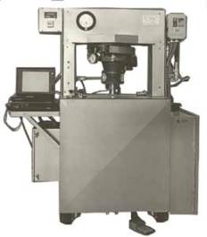
The development of the gyratory concept is attributed to Philippi, Raines, and Love of the Texas Highway Department.(3) The first Texas gyratory “press” was a manual unit used on an experimental basis from 1939 to 1946, (Figure 1). In 1946, the Texas Highway Department standardized its use in specifications and test methods.
In the 1950’s, John L. McRae, with the U.S. Corps of Engineers, most likely building on the principles of the Texas Highway Department, developed the U.S. Corps of Engineers “gyratory kneading compactor,” (Figure 2). This device was developed in response to experience in the 1950’s, which showed the Marshall impact hammer did not suitably simulate wheel path densities under heavy aircraft. McRae also believed the mechanical properties of the test specimens produced by the Marshall impact hammer did not simulate the properties of specimens taken from pavements. In 1957, a U.S. patent application was filed.
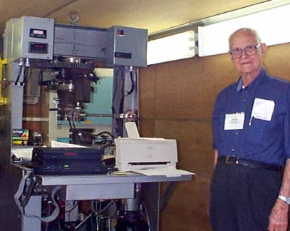
Unique to the Corps device, the gyratory action is induced using a two-point system, which allows the angle of gyration to flow during compaction. The floating angle is measured during compaction and incorporated into the associated design procedure. In addition, the device captures the pressure in the two-point system and the specimen height. By 1993, McRae advocated computation of mix stiffness values called “gyratory shear modulus” and “gyratory compression modulus.” By that time the Corps device was known as the Gyratory Test Machine (GTM), (Figure 3).
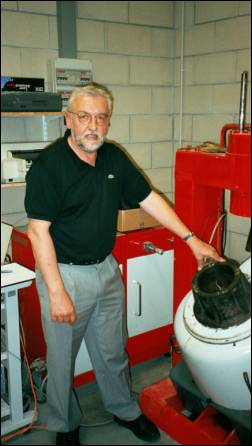
Another offshoot of the Texas gyratory concepts was a series of devices developed by the Laboratoroire Central des Ponts et Chausées (LCPC) in France. Unlike the Corps device, the LCPC gyratory is referred to as the PGC, (Figure 4). This device has a fixed external, mold wall angle of one-degree with a compaction pressure to 600 k Pa, (See Appended Timeline). The LCPC compactor is used as an initial screening test to optimize mix composition. Mechanical property tests are subsequently used to fine-tune a proposed mixture.
The European asphalt community, as part of their specification harmonization effort, is currently considering adoption of the LCPC concepts of laboratory compaction and design.
Development of the SHRP Gyratory Compactor
The United States Congress in 1987 authorized the Strategic Highway Research Program (SHRP). This effort was conducted from 1987 to 1993. Initially, SHRP focused on asphalt binder research. In 1990, SHRP expanded efforts to include research in the area of asphalt mixtures – building on the work of National Cooperative Highway Research Program (NCHRP) AAMAS (4) and the work of LCPC in France. AAMAS is an acronym for asphalt-aggregate mixture analysis system. AAMAS was conducted under NCHRP project number 9-06. The principal investigator was Harold L. Von Quintus with Brent Rauhut Engineering, Inc.
AAMAS identified the Corps GTM as an effective means of fabricating and testing asphalt specimens. In addition, AAMAS identified the Texas gyratory shear test machine as an acceptable substitute for the GTM in the fabrication of asphalt specimens. The use of gyratory compaction was based on a comparison between field cores and laboratory specimens. As part of the AAMAS contract, four workshops were conducted in the spring of 1991, across the country, giving an overview of their findings.
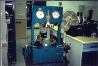
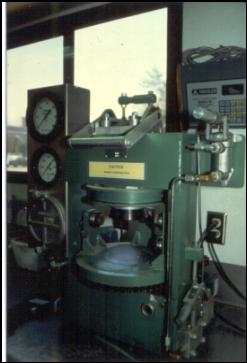
In the summer of 1990, FHWA initiated Demonstration Project No. 90 (DP 90), then entitled, “Innovative Asphalt Mix Laboratory Techniques.” DP 90, using a mobile laboratory, was designed to demonstrate the findings of AAMAS and SHRP-as findings became available. In FHWA’s review of AAMAS, the use the GTM in the DP 90 trailer was deemed impractical and the functionality of the Texas gyratory shear test machine was deemed somewhat deficient. FHWA developed a concept for a hybrid gyratory – with the portability and fixed angle of the Texas unit that incorporated testing measures similar to the GTM and the French LCPC compactor. Texas gyratory shear test machines are only commercially available through the Rainhart Company located in Austin, Texas (Figure 5). In January 1991, the FHWA approached Rainhart to upgrade their existing compactor, the gyratory shear test machine.
In April of 1991 in Atlanta, Georgia, during one of the four AAMAS workshops, FHWA proposed the hybrid gyratory compactor, which was designed to overcome issues with the two compactors recommended by AAMAS, specifically, the GTM's size and cost, and the Texas gyratory's high angle of compaction (6°). The high angle of gyration employed by the Texas gyratory causes compaction to occur relatively quickly, within around 15 to 18 gyrations, and does not allow for a comparative measure of compact-ability between mixes.
In May 1991, the Rainhart Company was awarded a contract for the manufacture of one modified gyratory shear-testing machine, (Figure 6). In the Fall of 1991, building on the work of LCPC, the Asphalt Institute, SHRP A-005 contractor, attempted to fabricated a French style gyratory with a fixed 1° angle from a Texas Highway Department manufactured Texas 6-inch gyratory, (Figure 7). This effort was lead by McGennis, Huber, Anderson, and Blankenship.
The majority of the mixture testing conducted during SHRP by the Asphalt Institute was conducted on this modified Texas 6-inch gyratory. Investigation by FHWA on this device showed the mold wall angle was 1.23°, not 1° as originally desired. The Asphalt Institute adjusted the modified Texas 6-inch gyratory down to 1° and subsequently attempted a mix design for the Arizona Department of Transportation. The Arizona mix would not compact down to 4 percent air voids at the lower angle of gyrations. The SHRP researchers deduced that the 1° angle employed by the French, to address initial construction densification, was insufficient for a mix design procedure targeting 4 percent air voids. The angle was adjusted back up and the research was completed at the higher angle.
Discussion by the SHRP researchers lead to the final specification for the SHRP gyratory compactor:
- Vertical consolidation pressure of 600 kPa,
- Fixed angle of gyration of 1.25°, and
- Speed of gyration of 30 rpm.
Based on experimentation, the SHRP researchers established an allowable tolerance on the angle of +0.02°. This tolerance is intended to limit the net effect of angle on the design asphalt binder content by 0.1 percent. A tolerance of +10kPa was initially assigned to the pressure based upon engineering judgment.
As part of FHWA’s implementation effort of the SHRP research products – FHWA established a national pooled fund equipment program to purchase the required new test equipment for State highway agencies. Prior to the pooled fund procurement of the SHRP gyratory compactor (SGC), FHWA hosted a manufacturers’ meeting to discuss the purchase specification. Invitations were extended to EDCO, Pine Instruments Company, Rainhart Company, Troxler Electronics, and other manufacturers of asphalt compaction equipment. Issues of tolerances were central throughout the discussion.
A tolerance of +0.5 rpm was determined to be reasonable for the speed of gyration. The proposed tolerance for the consolidation pressure was considered to be too tight. Manufacturers recommended a tolerance based on a percentage of the total pressure of 10-percent (60 kPa) for the initial 5 gyrations and 3-percent (18 kPa) thereafter. Today this is only partially reflected in AASHTO T312-01(8), previously AASHTO TP4-99, as +18 kPa throughout the compaction cycle.
The manufacturers also indicated the tolerance for the angle of +0.02° was very tight and would raise the cost of the device. FHWA stressed that this was based on a detailed review of data by the SHRP researchers. It had been estimated that a SHRP gyratory compactor would cost approximately $15,000, however, this specification resulted in compactors costing around $25,000.
FHWA solicited manufacturers for the pooled fund purchase. Pine and Troxler were the successful bidders. The procurement required each manufacturer to provide FHWA with one “first article” unit. The first article units were evaluated by FHWA at the Asphalt Institute for compliance with the SHRP specification. The evaluation did not provide acceptance of the first article units on a comparison of compacted specimens’ volumetric properties. The units were tested to determine if they applied the appropriate angle, pressure, and speed, (see Appended excerpt from the original procurement specification).
The specification did not assign a tolerance for the parallel-ness or perpendicular-ness of the mold base plates and the mold wall. Also, the method of angle calibration was left to the manufacturer. The method needed only to be “a clear and simple means.”
While acceptance was not based on a comparison of volumetrics, during the first article evaluation, mix was compacted in the two first article units and compared to the modified Texas 6” gyratory. The data showed that one of the new units differed significantly from the modified Texas 6” gyratory. The other new unit showed no such difference.
When compared to the modified Texas unit, the Pine gyratory constantly compacted specimens well within the allowable tolerance for bulk specific gravity (AASHTO T166 precision is 0.02). The difference between the average of six specimens was below 0.003. When compared to the modified Texas unit, the Troxler gyratory constantly compacted specimens with lower densities and outside of the allowable tolerance.
After an extensive discussion with the SHRP researchers and the manufacturers, it was determined the only apparent difference among the three units was mold wall thickness. The Pine and the Texas units’ mold walls were very similar in thickness. While the mold walls of the Troxler unit were much thinner. It was deduced that a thinner mold wall was allowing the specimen to cool quicker - thus increasing the mix stiffness and decreasing the compacted specimen’s density. Although the Troxler unit had fully passed the first article evaluation criteria, the unit was redesigned with a thicker mold wall in an effort to make the two units more comparable. Retesting with the new molds showed only a slight difference between the two new compactors. Because the difference was within the allowable precision of AASHTO T166, the decision was made to proceed with both the manufacturers’ units for the pooled fund purchase for the State highway agencies.
An Alternative Path
During the SHRP research program intense debate was held on the effectiveness and appropriateness of gyratory compaction. Professor Carl Monismith, University of California – Berkeley, advocated for the adoption of rolling wheel compaction over the gyratory. Professor Monismith cited problems with gyratory specimen uniformity in both the radial and vertical directions. He considers specimen uniformity critical when using measuring engineering properties in laboratory performance testing. However, rolling wheel compaction proved to be somewhat impractical as a sole means of laboratory compaction – the equipment proposed was large and required very large batches of mixture.
FHWA conducted compaction comparisons in two mobile laboratories throughout the implementation of the Superpave system. During the evaluation process, production mix was sampled, split, and allowed to cool. A split was then shipped to the other mobile laboratory. Samples at both laboratories were reheated and compacted.
During 1994 and 1995, the two mobile laboratories performed nine such comparisons. Each involved compacting a total of six gyratory specimens – 3 at each laboratory. Statistical analysis of the data, using a one-sided F-test and the paired Student “t” test, showed no statistically significant difference in the volumetric results (based on Gmb) from the two devices.(5) However, 7 of the 9 studies showed the Pine SGC compacted to a greater density than the Troxler SGC. In one study the difference was 0.017. However, this was still within T166 precision, but a difference this high equates to a difference of approximately 0.7 % air voids. This could be critical for a Contractor in the field management of a production mix.
For the nine comparison studies, the difference in Gmb for the Pine compacted specimens averaged 0.005 higher than the Gmb for the Troxler compacted specimens.
In
2000, FHWA expanded the previous comparison study to include 30 production mixes.(6)
These mixes were from projects throughout the United States and produced between
1994 and 2000. Statistical analysis of the data, using a one-sided F-test,
showed the variances of the volumetric results were not statistically significant.
However, the paired Student “t” test showed the means of the volumetric results
(based on Gmb) were statistically significant. On average, the
difference in Gmb between the two compactors was still 0.005. However,
this difference is statistically significant, (as the number of projects
increases, the statistical criteria for acceptance become tighter). It
was concluded that the most likely cause is variation in the internal angle
of gyration, (Figure 8).
Today, over 2000 Superpave gyratory compactors are in use in the United States for the design and field management of asphalt mixtures. Five companies currently manufacturer SGC’s for use in the United States offering a total of eight different models. Each model employs a unique method of setting, inducing, and maintaining the angle of gyration. A calibration system is required in each device to measure the angle of gyration. All measurements are made externally relative to the mold wall. No manufacturer’s calibration systems can be used universally on all of the different models commercially available.
It would appear that internal angles are not controlled uniformly among the devices. Greater than allowable precision differences in bulk specific gravities between specimens compacted in different Superpave gyratory compactors have been reported in the field.(7) The precision stated in AASHTO T166 of 0.02 equates to a difference in calculated air voids of approximately 0.8 percent.
Many of the differences reported can be attributed to differences in testing procedures. Leeway within AASHTO specifications can result in measurable differences. Uniform sampling, splitting, and handling practices are critical for obtaining repeatable and comparable results. The Superpave Mixture/Aggregate Expert Task Group (ETG) has developed a standard practice to address within-procedure differences.(9)
However, measurable differences in compacted specimen specific gravities have been attributed to differences in compaction equipment. Currently, SGCs have to comply with AASHTO T312-01, where calibration is a function of pressure, speed, and angle of gyration. The angle is defined by the mold wall angle relative to a fixed reference plane. The upper and lower platens are assumed to be parallel. Compliance issues within the equipment affect parallel-ness and are not addressed in the specification.
In response to this issue, FHWA has developed an angle validation kit (AVK) to measure the internal angle of gyration in any SGC, (Figures 9 and 10). The AVK is designed to operate inside a standard mold, during compaction, with HMA. The Superpave Mixture/Aggregate ETG is guiding research associated with the AVK. Several issues need to be addressed before the AVK can be considered in standard practice:
- The AVK must be validated and NIST-traceable.
- An AASHTO procedure must be developed.
- Target and Tolerances for a standard internal angle must be established.
Efforts are underway to address all of these issues. In the interim, the Superpave Mixture/Aggregate ETG recommended the “Standard Practice for the Evaluation of Different Superpave Gyratory Compactors (SGCs) Used in the Design and Field Management of Superpave Mixtures,” be used to address issues of compactor comparison. If issues cannot be resolved by these means, users are encouraged to work with their manufacturers to address differences. Some State highway agencies are developing offset procedures to address differences in compactive effort that is equipment related.
It is anticipated that many o the issues related to the AVK will be addressed by the end of 2001. The final product of this research is the refinement of AASHTO T312-01 to include tolerances on parallel-ness.
The Superpave gyratory compactor and the French PGC can be effective tools in the design of hot-mix asphalt. The issues associated with compactor comparability will be addressed in the near future, but these tools are only effective in the hands of experienced technologists. As an industry we must strive to educate and foster the men and women who make our transportation system able to handle the challenges of the future.
References
Appendix
Excerpt - Original FHWA Pooled Fund Procurement Specification:
The angle of gyration was specified as follows in original procurement specification:
1.01 Specimen Orientation: For this specification, the horizontal plane shall be defined as the XZ-plane and the vertical direction shall be defined as the Y-axis. The cylindrical specimen shall have a height of H and diameter of ID, (figure not shown). The cylindrical specimen shall be orientated with the height, H, parallel to the Y-axis, (the height is the perpendicular distance between the top and base of the cylinder). The top and base of the cylindrical specimen shall always be parallel to one another. During compaction the cylindrical specimen will be skewed at a fixed angle. This angle is defined as the Angle of Gyration: Alpha (α).
1.02 Parameters Of Compaction: Three parameters define the level of compaction effort provided to a specimen:
1.02a Consolidation Pressure: the vertical pressure applied to the specimen during gyration along the Y-axis, (kilo-Pascals).
1.02b Angle of Gyration: the angle created between the cylinder sides and the Y-axis during gyration, (degrees).
1.02c Speed of Gyration: the rate at which gyration occurs, revolutions per minute, (rpm).
2.02b Angle of Gyration, (α - Alpha in Degrees): The Angle of Gyration (α) shall be held constant (fixed) during gyration of the specimen. The Angle of Gyration (α) specified by SHRP is 1.25 degrees (± 0.02E). The operator shall through clear and simple means be able to induce and remove the specified angle before and after gyration. To address HMA mixes that may require different angles of gyration for compaction and to correct for wear within the compactor, the angle of gyration shall be adjustable ± 0.75 degrees in increments down to 0.02 degrees. This adjustment shall be clear and simple to perform.
3.01 Calibration: The operator shall through a clear and simple means be able to calibrate all parameters of compaction. The required tools and methods shall be supplied with each SUPERPAVE Gyratory Compactor; specifically:
(1) The Vertical Consolidation Pressure,
(2) The Angle of Gyration, (α): measured with HMA in the gyratory mold while gyration is not occurring (statically at 5, 10, 50, 100, 150, and 200 gyrations.
(3) The Speed of Gyration.
|
Timeline |
Device/Agency |
Specimen Size |
Compaction Effort |
|
1939 |
Concept |
D – 4” |
P – Unknown |
|
1946 |
TX Highway Department |
D – 4 & 6” |
P – Variable |
|
1957 |
US Corps Engineers |
D – 6” |
P – Variable |
|
1960’s |
First Prototype Texas at LCPC, France |
D - ? |
P – Variable |
|
1968 |
Second Prototype Texas at LCPC, France |
D – 80 or 120 mm |
P – Variable |
|
1974 to |
PCG1, PCG2 at LCPC, France |
D – 160 mm |
P – 600 kPa |
|
1991 |
Modified Gyratory Shear Test Machine, FHWA |
D – 4” |
P – 600 kPa |
|
1991 |
Modified TX Highway Department, SHRP |
D – 6” |
P – 600 kPa |
|
1993 |
SHRP/Superpave Gyratory Compactor in USA |
D – 150 mm |
P – 600 kPa |
|
1996 |
PCG3 at LCPC, France |
D – 150 mm |
P – Fixed 500 to 800 kPa |
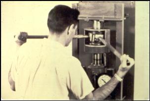
Figure 1. Texas Gyratory Press
Figure 2. U.S. Corps of Engineers Gyratory Kneading Compactor
Figure 3. 2000, John L. McRae (EDOC) and the GTM
Figure 4. 2001, Francis Moutier (LCPC) with the PGC-2
 |
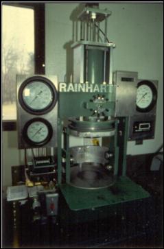 |
| Figure 5. 1987, Rainhart Company, Gyratory Shear Test Machine | Figure 6. 1991, Rainhart Company, Modified Gyratory Shear Test Machine |
Figure 7. 1991, Modified Texas 6” Gyratory
Figure 8. External Mold Wall Angle versus Internal Angle of Gyration
Figure 9. FHWA Angle Validation Kit (AVK) - uses a springed LVDT to measure the movement between the mold wall and the end platen.
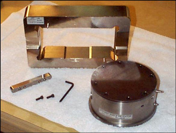
Figure 10. Test Quip AVK with NIST traceable verification fixture.
Development of the LCPC Gyratory - Time Line
(By Francis Moutier – provided in French and English Translation)
(By Francis Moutier – English Translation)
· 1940’s: Development at Texas Highway Department of a device imposing shear during the axial compaction of a cylindrical test-specimen of hot mix asphalts [ [i] ].
· Early 1960’s: From the ideas developed by the Texas Highway Department, construction of the first prototype of a Texas-type press by the Centre d’Etude et de Construction de Prototypes d’Angers (CECP – Ministry of Public Work's Center for Construction of Prototypes). Evaluation by the engineers of the time [ [ii] ].
· 1968: Construction of the second prototype of gyratory compactor by CECP Angers. Initially designed for molding test specimens, later used to study the compaction of hot mixes at the beginning of the Seventies.
· 1972: The study of the discriminatory possibilities of the compaction by gyratory shearing on the second prototype leads to the development of the analysis of the test results based on plots of compacity versus log of number of gyrations [ [iii] ]
· 1972: The specifications sheet for the first generation of series-produced presses was established.
· 1973-74: Production and evaluation of the first generation of french gyratory shear compactor (PCG1) within the strict framework of the new methods of data analysis, and without drawing aside the possibility of molding specimens with varying diameters and heights. Two crucial observations were reported [ [iv] ]: i) the technology used to apply the shearing angle led to compactions different than those obtained with the second 1968 prototype ; ii) the density of PCG-molded specimens was found to be heterogeneous.
· 1974-80: Study of the relevance of PCG using the real-size slab-compactor built by CECP Angers [ [v] ]. Establishment of the relationship between number of gyration ng and number of passes of roller np [ [vi] ]: ng = K.e.np, where K is a proportionality factor describing the efficiency of the roller (vibrating or not, pneumatic or steel wheel,...) and e is the thickness of the compacted pavement layer.
· 1977: Publication of an article summarizing the possibilities of PCG in the special issue of BLPC "Bitumes et Enrobés Bitumineux" (Bituminous Binders and Mixes) [ [vii] ].
· 1980-81: Release of a first draft of the procedure to establish the compaction curves of hot mixes using the PCG by LCPC. The first round robin test was then realized with all the available PCGs: variance of repeatability on the compacity after 40-120 gyrations was 0.24 (on one elementary test) and variance of reproducibility was 0.54.
· 1985-86: The second generation of PCG was launched. The PCG2 machines were more compact, but the shearing technology remained the same as that of PCG1. This way, the unwanted effect of mix resistance on the shearing angle during compaction (which was already observed on PCG1), was preserved. Thus the accuracy of test results was preserved, as proven by the 1995 round robin test: variance of repeatability on the compacity after 60 gyrations was 0.16 (on three elementary test), variance of reproducibility was 0.25 [ [viii] ].
· 1992: A new specifications sheet was deposited. It was aimed at making a third generation of PCG's that would be very compact and therefore easily portable for on-site testing. Moreover the shear rigidity of the device was adapted so that a constant angle of shearing could be maintained throughout the compaction process.
· 1993: The speed of 30 rpm was adopted to reduce testing time, following a suggestion by SUPERPAVE representative G. Huber.
· 1996: The prototype of PCG3 was produced and tested.
· End of 1996: A PCG Seminar organized by LCPC in Nantes (France) allowed profitable exchanges between PCG users. At this occasion, the prototype of PCG3 was presented.
· 1997-99: The revised French standard was accepted [ [ix] ]. It took into account the characteristics of the new PCG3 so that this new model gave compaction curves similar to those obtained with the old PCG1 or 2 models. This necessitated the use of «external» parameters of adjustment, which were not the same for PCG1-2 and PCG3. Moreover according to the new standard, any type of compactor, (all kinds of PCG's and others), which underwent the qualifying heat could be used for specification purposes (Appendix A1 of standards NF P98-252 and prEN 12697-31 [ [x] ]). The qualifying heat consists in compacting two reference materials with the device to-be-evaluated and compare its response to the standard compaction curve for the reference materials.
· Since 1999: PCG3 is marketed in place of the old models. The procedures of qualification and of conformity [ [xi] ] according to A2 Appendix of standards NF P98-252 and EN 12697-31 developed for every model makes it possible to manage the control of production as well as the annual follow-up without problem.
· 2000: A large quantity of reference materials is stored at LCPC Nantes, so that appendix A1 of the standard could be applicated.
· 2001: A recent trial with the AVK sensor of angle from FHWA made it possible to confirm on three commercial PCG3, that PCG3 has excellent behavior: i) very good stability of angle during compaction, ii) similar values for the angle measured either at the bottom and on top of the specimen.
[ [i] ] Ortolani L. and H. A. Sandberg, "The gyratory-shear method of molding asphaltic concrete test specimens; Its development and correlation with field compaction methods. A Texas Highway Department standard procedure", Proc. Assoc. Asphalt Paving Technol. 21, pp.280-297, 1952
[ [ii] ] Sauterey R., "Confection d'éprouvettes de matériaux enrobés. Le compactage par pression et cisaillement giratoire", Bulletin Liaison Ponts Chaussées 5, part 3 pp.1-6, 1964
Passebon J. and M. Peignaud, "Moulage d'éprouvettes d'enrobés sur la presse dite Texas d'Angers. Comparaison avec les procédés classiques", Bulletin Liaison Ponts Chaussées 5, part 4 pp. 1-18, 1964
Rollin M., "Etude de l'homogénéité de la compacité dans les éprouvettes type Duriez et type Texas", Bulletin Liaison Ponts Chaussées 5, part 5 pp.1-8, 1964
[ [iii] ] Moutier F., "La presse à cisaillement giratoire", Bulletin Liaison Ponts Chaussées 68, pp.141-151, 1973
[ [iv] ] Moutier F., "La presse à cisaillement giratoire, modèle de série", Bulletin Liaison Ponts Chaussées 74, pp.137-148, 1974
[ [v] ] Moutier F., "Le banc de compactage du laboratoire régional d'Angers", Bulletin Liaison Ponts Chaussées 88, pp.132-136, 1977
[ [vi] ] Moutier F., "Prévision de la compactibilité des enrobés bitumineux à l'aide de la presse à cisaillement giratoire", Bulletin Liaison Ponts Chaussées 121, pp.29-40, 1982
[ [vii] ] Moutier F., "Utilisations et possibilités de la presse à cisaillement giratoire", Bulletin Liaison Ponts Chaussées Special V, pp.173-180, 1977
[ [viii] ] Delorme J.-L., "Essai à la presse à cisaillement giratoire. Expérience d'exactitude", Bulletin Liaison Ponts Chaussées 211, pp.15-24, 1996
[ [ix] ] NF P98-252, Essais relatifs aux Chaussées - Détermination du comportement au compactage des mélanges hydrocarbonés - Essai de compactage à la presse à cisaillement giratoire, AFNOR, juin 1999
[ [x] ] prEN 12697-31, Bituminous mixtures - Test methods for hot mix asphalt - Part 31: Specimen preparation gyratory compactor, CEN, july 2001
[ [xi] ] Corte J.-F., F. Moutier et H.Vialletel, "The PCG3, last development in the technology of the gyratory compactors", Revue Gén. Routes Aérodromes 771, pp.20-24, 1999