U.S. Department of Transportation
Federal Highway Administration
1200 New Jersey Avenue, SE
Washington, DC 20590
202-366-4000
Federal Highway Administration Research and Technology
Coordinating, Developing, and Delivering Highway Transportation Innovations
 |
| This report is an archived publication and may contain dated technical, contact, and link information |
|
Publication Number: FHWA-HRT-06-121 Date: November 2006 |
One of the additional objectives indicated in the proposal for this research was for the contractor to make:
"…recommendation as to ways in which mechanistic design methods can appropriately consider the most effective adaptations or materials standards to minimize the acceleration of pavement damage due to freezing and thawing."
NCHRP 1-37A Guide procedures basically model a set pavement section and determine the stresses and strains that are produced in that pavement section based on given material properties and dimensions, as well as the loads imposed on those materials. These strains are compared to empirically based damage models to determine the incremental damage for each loading. The incremental damage values are totaled over time to predict the performance of the selected pavement section relative to the specific damage categories (i.e., rutting or fatigue cracking). While only a limited amount of local adaptations were discovered in this study, most can be accounted for in the M-E design procedures.
The effect of local adaptations in M-E design procedures can be applied to the basic material properties or to the empirical damage models. Increasing the depth of frost-free material can be reflected in the M-E design procedures through an adjustment to the material strength properties (i.e., thaw weakening will not be as pronounced, yielding less reduction in subgrade stiffness during the springtime). This same local adaptation can also be accounted for by adjusting the empirical damage models so that the accumulation of deterioration is less rapid over time, given the same stress and strain.
The use of additional frost-free material incorporated either in the pavement design or as a specific subgrade treatment can be accommodated in most mechanistic design procedures. Seasonal subgrade stiffness variation can be accounted for by inputting into the design strength parameters and the duration at which they occur. In these cases, the added frost-free layers are considered as either an improved subgrade or added subbase in the program. For instance, the basic AASHTO pavement design used for the cost analysis described in the previous chapter produced a pavement section consisting of 150 mm (6 inches) of ACP over 205 mm (8 inches) of untreated base. Constructing this section over frost-susceptible soil and in an area experiencing 1 m (3 ft) or more of frost penetration would result in a structure that is significantly weakened during spring thaw—possibly a reduction of up to 50 percent in the subgrade stiffness. This is addressed in the 1993 AASHTO Guide for Design of Pavement Structures(1) by using the effective modulus to account for the reduced springtime stiffness. In a design procedure based on the NCHRP 1-37A Guide, the increased damage accrued during the spring weakening of the subgrade can be accounted for in the program by a reduction in the subgrade stiffness and subsequent increase in stresses incurred during that period as a result of the lower stiffness. If the subgrade soil was replaced with 0.6 m (2 ft) or more of frost-free material, as is done in several of the PFSs, the stiffness of the subgrade can be increased because of the increased layer thickness and the reduced spring weakening effects. Combined, these inputs reduce the tensile stresses on the bottom of the pavement as well as reducing the compressive stresses on the top of the subbase and subgrade layers, thus resulting in longer service life for the pavement section being analyzed.
The NCHRP 1-37A Guide pavement design procedure (2) was developed using damage models that represent average pavement damage trends for the entire United States. The program computes different stress levels in a pavement section depending on the input, which can reflect different material properties based on environmental input. The empirically based damage models, however, were developed to produce the same increment of damage in New York, Los Angeles, and Chicago for a given stress. This was done so that the program could produce reasonable results throughout the country. This is acknowledged in the NCHRP 1-37A Guide (2), which provides a process for agencies to calibrate the damage models to local conditions.
Section 3.3.6 of the NCHRP 1-37A Guide describes the need and recommended approach for local calibration of the M-E models. Following are specific directions recommended in the report:(2)
Because this design procedure is based on mechanistic principals the procedures should work reasonably well within the inference space of the analytical procedure and the performance data from which the procedure was calibrated. However, this is a very complex design procedure and it must be carefully evaluated by highway agencies wishing to implement. The following is the recommended calibration/validation effort required to implement this mechanistic-empirical design procedure….While all five items listed above are necessary in the M-E implementation process, the last two address the adjustment of the M-E damage curves to match local experience. These processes were thoroughly explored with consideration given to the use of the models discussed in chapter 5 in accomplishing local calibration and validation. The following excerpts were taken directly from the NCHRP 1-37A Guide:(2)
In light of these guidelines, a few SHAs are now in the process of refining the calibration factors for the performance models. The University of Washington is developing calibration factors for the WSDOT, which is described in the PCCP Models for Rehabilitation and Reconstruction Decision-Making report.(29) The steps outlined in the NCHRP 1-37A Guide were followed in the referenced work. The comparative analysis considered three major categories for rigid pavement performance: undoweled short jointed PCCP, undoweled short jointed PCCP mountain passes, and doweled bar retrofitted PCCP. Information from the SHA pavement management system, which contains more than 30 years of performance data for all pavements in the network, was used in steps four and five. Typical pavement sections consistent with those in place were used to estimate pavement performance for the three categories of pavement using the 1- 37A M-E design program. The resulting predictions were then compared to the average performance history for each category. Through several cycles of iterations, and a subsequent verification activity, a new set of C values were developed for the cracking and faulting models for the three categories of PCCP in Washington State.
Not all SHAs have the advantage of having 30-plus years of network wide continuous pavement condition data. Those that do not may be able to fine-tune the NCHRP 1-37A Guide output through the use of the models described in chapter 5. That would be particularly true for those agencies that have an environment significantly different than what would be represented by the national models developed for the M-E design procedure. The models developed in this project could be used to predict average rutting or fatigue cracking trends for a specific (regional or statewide) environment. These estimates could be used to then go through the same iteration and verification process described in the NCHRP 1-37A Guide, or the WSDOT research project, to determine if modified calibration factors are needed in the design program to accurately reflect performance in the SHA. An example of the NCHRP 1-37A Guide calibration methodology flowchart is shown in appendix G.
To provide an example of the use of the models described in chapter 5, the calibration process outlined in the NCHRP 1-37A Guide was performed for a typical site in North Carolina. This sample calibration was performed for the basic roadway design parameters and pavement design section used in the economic analysis (chapter 9 of this report) for a rural primary highway. The representative climate for North Carolina presented in table 22 was used for environmental inputs.
In the NCHRP 1-37A pavement design program there are input procedures that allow the user to adjust the damage models used for fatigue cracking, rutting, and thermal cracking. For the AC fatigue cracking model there are three calibration factors (referred to as Bf1, Bf2, and Bf3) that adjust the K1, K2, and K3 correlation coefficients. In the current version of the NCHRP 1-37A pavement design software, these calibration settings can be found through the tools menu and the calibration settings for new flexible pavement under "Distress Model Calibration Settings–Flexible." Four categories of calibration conditions are available for AC fatigue analysis:
The same set of inputs is available for AC rutting, except that the adjustments for K1, K2, and K3 are termed Br1, Br2, and Br3, respectively. Conversely, only the State/Region Calibration category is available for AC thermal fracture with the adjustment inputs termed Bt1, Bt2, and Bt3 respectively.
Similar adjustments are available for chemically stabilized material (CSM) fatigue and subgrade rutting. The correlation coefficients (C1 through C4 and C1 through C6) can be individually modified for the AC cracking, CSM cracking, and IRI categories.
The roadway section used for this sample consisted of 150 mm (6 inches) of hot mix asphalt (HMA) concrete pavement over 205 mm (8 inches) of granular base with a finegrained, frost-susceptible subgrade soil, which was assumed to be A-6 soil as defined in the AASHTO classification system.(30) The values input into the NCHRP 1-37A pavement design software matched the mix properties and typical specifications provided by North Carolina. The traffic loading was input as load spectra, but it was very similar to the 3 million ESAL loading over 20 years used in previous analysis described in this report.
The calibration process consisted of running the NCHRP 1-37A pavement design software with the national calibration factors to estimate performance and compare output to the predictions of the models from this study. The NCHRP 1-37A pavement design software (using the nationally calibrated models) indicated that the pavement would experience rapid top-down cracking with an accumulation of more than 750 m/km (4,000 ft/mi), more than 13 mm (0.5 inch) of rutting, and ride values progressing from 1 m/km (64 inch/mi) to more than 8.3 m/km (525 inch/mi) in 20 years. The design section used for this analysis was developed using the 1993 AASHTO Guide for the Design of Pavement Structures(1) with 85 percent reliability, so it did not seem reasonable for it to experience that much longitudinal cracking and ride deterioration. Looking at the pavement distresses recorded at the various LTPP sites around North Carolina, similar pavement sections have not experienced that level of distress accumulation over a 20- year period. Dominate pavement distress recorded at the LTPP sites in North Carolina consisted of some fatigue cracking, isolated transverse cracking, and rutting, so regional calibration seemed appropriate. For this example, that calibration focused on the accumulation of fatigue cracking, rutting, and ride values because those were the predominant distresses indicated by the local LTPP sites. The calibration was achieved through an extensive iterative process of varying either the B values for the fatigue and rutting models or the C values for the ride model.
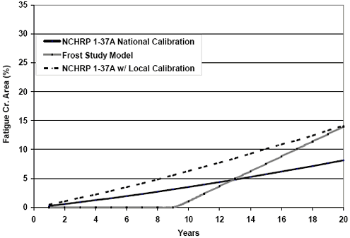
Figure 76 provides the fatigue cracking predictions for the sample design. The NCHRP 1-37A damage trends for fatigue cracking are generally continuous trends without the observation of a crack initiation point, which is included in the models developed under this study. The calibration was thus set to match the frost model at 20 years, but it could have been adjusted to fit the model at 10 or 15 years as well. The Bf1 term was set at 0.47 to provide the NCHRP 1-37A Guide fatigue cracking prediction shown in figure 76 as local calibration.
Figure 76. Graph. Comparison of fatigue cracking trends before and after local calibration.
The rutting prediction model developed in this study and the NCHRP 1-37A Guide model are similar in form. Therefore, the NCHRP 1-37A rutting models could be calibrated to local conditions for the full range of the pavement ages as opposed to the fatigue models which had to be calibrated at a certain age. The Br1 factor was set to 0.1 to obtain the rutting prediction for the local calibration shown in figure 77. This resulted in rut development predicted primarily in the base and subgrade soils by the NCHRP 1- 37A design software. Similar trends were also developed by increasing the Br1 factor to above 1 and setting the Bs1 terms to 0.05 or less, which moved the rutting prediction from occurring in the subgrade and aggregate base to occurring in the HMA based on the NCHRP 1-37A design software. Either approach provided the same basic rutting trend over time.
Figure 77. Graph. Comparison of rutting trends before and after local calibration.
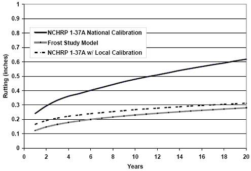
1 inch = 25 mm
Similar to the rutting models, the form of models for ride deterioration in terms of IRI was also consistent over time; therefore, the NCHRP 1-37A model could be calibrated over the full range of pavement ages and not at a specific age. The C values were adjusted to bring the NCHRP 1-37A model more in line with the ride model developed for this study using the North Carolina conditions. As can be seen in figure 78, a very good fit was achieved after the local ride calibration. To get this fit, the C1 value was lowered to 0.10 of the value for the national calibration. The rest of the C values were not as sensitive as the C1 value in providing a better fit to the performance model from this study.
Figure 78. Graph. Comparison of ride trends before and after local calibration.
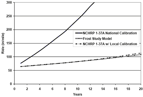
100 inches/mi = 1.5 m/km
This was one set of iterations for a pavement with 150 mm (6 inches) HMA over 205 mm (8 inches) of granular base. Similar iterations would need to be performed on a range of pavement sections with both higher and lower traffic loadings and the resulting average calibration factors would then be used to produce pavement design performance predictions that would be calibrated to the local environmental conditions.
This type of calibration procedure should be used only if the local agency does not have its own performance data for developing local calibrations for use in the NCHRP 1-37A pavement design software. If an agency has limited pavement performance data, the models developed in this study could be used to estimate general pavement performance trends adjusted to fit the relative values of the local data in a process similar to that described in the next chapter on pavement management systems.
The performance trends from this study were developed with the intent to represent a broad array of inservice pavements throughout North America. As such, the contributions of surface treatments such as chip seals were not incorporated in the models and cannot be used to calibrate the NCHRP 1-37A Guide performance curves for sealed HMA pavement. SHAs using these treatments must develop damage models that are specific to the performance of pavements with surface treatments.

