U.S. Department of Transportation
Federal Highway Administration
1200 New Jersey Avenue, SE
Washington, DC 20590
202-366-4000
Federal Highway Administration Research and Technology
Coordinating, Developing, and Delivering Highway Transportation Innovations
 |
| This report is an archived publication and may contain dated technical, contact, and link information |
|
Publication Number: FHWA-HRT-08-035 Date: March 2008 |
The new approach for calculating dielectric constant in this project utilizes the transmission line equation (TLE). The following describes the basic theories and concepts of electromagnetics and the TLE.
In the study of electromagnetics, the four vector quantities called electromagnetic fields, which are functions of space and time, are involved: (2)
| E | = electric field strength (volts per meter, V/m) |
| D | = electric flux density (coulombs per square meter, C/m2) |
| H | = magnetic field strengths (amperes per meter, Am/m) |
| B | = magnetic flux density (webers per square meter, wb/m2) |
The fundamental theory of electromagnetic fields is based on Maxwell's equations governing the fields E, D, H, and B:
![]() (51)
(51)
![]() (52)
(52)
![]() (53)
(53)
![]() (54)
(54)
Where:
| J | = electric current density (Am/m2) |
| ?v | = electric charge density (C/m3) |
J and ?v are the sources generating the electromagnetic field. The equations express the physical laws governing the E, D, H, and B fields and the sources J and rv at every point in space and at all times.
In order to understand concepts of Maxwell's equations, some definitions and vector identities are described. The symbol ? in Maxwell's equations represents a vector partial-differentiation operator as following,
 (55)
(55)
Where = unit vectors along the x, y, and z axes
If A and B are vectors, the operation ? x A is called the curl of A, and the operation ? x B is called the divergence of B. The former is a vector and the latter is a scalar. In addition, if f (x, y, z) is a scalar function of the coordinates, the operation ?f is called the gradient of f. The operator as a vector is only permissible in rectangular coordinates.
Some useful vector identities are as follows: (12)
![]() (56)
(56)
![]() (57)
(57)
![]() (58)
(58)
![]() (59)
(59)
Where: ![]() (60)
(60)
The Maxwell equation (55) can be presented using the vector identity (57) and multiplying both sides by ? as follows:
 (61)
(61)
Being replaced with equation 54, the conservation law for current and charge densities is defined as the following:
 (62)
(62)
The conservation law means that the rate of transfer of electric charge out of any differential volume is equal to the rate of decrease of total electric charge in that volume. This law is also known as the continuity law of electric charge. In fact, to solve electromagnetic field problems, it is essential to assume that the sources J and rv are given and satisfy the continuity equation. (12)
Constitutive relations can provide physical information for the environment in which electromagnetic fields occur, such as free space, water, or composite media. Also, they can characterize a simple medium mathematically with a permittivity, e, and a permeability, µ, as follows:
![]() (63)
(63)
![]() (64)
(64)
For free space such as air, µ = µ0 = 4p10-7 H/m and e = e0 = 8.85 x 10⁻¹² F/m
Time-harmonic data is the large class of physical quantities that vary periodically with time. While physical quantities are usually described mathematically by real variables of space and time and by vector quantities, the time-harmonic real quantities are represented by complex variables. (12) A time-harmonic real physical quantity V(t) that varies sinusoidally with time can be expressed as follows:
![]() (65)
(65)
Where:
| V0 | = amplitude, |
| ? | = angular frequency ( = 2pf ) |
| f | = frequency of V(t) |
| t | = time |
| f | = phase of V(t) |
Figure 33 illustrates V(t) as a function of time t.

Figure 33. Graph. Time-harmonic function V(t). (12)
The V(t) can be expressed by using the symbol of Re{ }, which means taking the real part of the quantity in the brace as follows:
![]() (66)
(66)
Hence, the derivation with respect to time can be expressed as
 (67)
(67)
So,
 (68)
(68)
As shown in equation 67, the time derivative ![]() t can be replaced by j?in the complex representation of time-harmonic quantities.
t can be replaced by j?in the complex representation of time-harmonic quantities.
Maxwell's equations can be expressed with respect to the complex representations for the time-harmonic quantities as follows:
 (69)
(69)
![]() (70)
(70)
![]() (71)
(71)
![]() (72)
(72)
Given that electromagnetic fields are generated in free space by source J and ?v in a localized region, then, for electromagnetic fields outside the region, J and ?v are equal to zero and Maxwell's equation can be expressed with free space constitutive relations of equations 63 and 64 as the following: (11)
![]() (73)
(73)
![]() (74)
(74)
![]() (75)
(75)
![]() (76)
(76)
By taking the curl of (73) and substituting (74), the following can be obtained:
![]() (77)
(77)
The wave equation for E can be obtained with regard to vector identity (56) and equation 74 as follows:
![]() (78)
(78)
The wave equation (78) is a vector second-order differential equation. The simple solution is expressed as follows;
![]() (79)
(79)
From equations 78 and 79, the following is obtained;
![]() (80)
(80)
The magnetic field H of the wave can be determined from equation 73 or 74:
 (81)
(81)
In equation 81, the factor ![]() is known as the intrinsic impedance of free space,
is known as the intrinsic impedance of free space,
 (82)
(82)
The wave has the electric field E in the ![]() -direction and the magnetic field H in the
-direction and the magnetic field H in the ![]() -direction and propagates in the
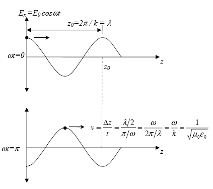
-direction and propagates in the ![]() -direction. Figure 34 shows the velocity of propagation with time in a sinusoidal wave.
-direction. Figure 34 shows the velocity of propagation with time in a sinusoidal wave.

Figure 34. Graph. Electric field as a function of z direction at different times.(12)
Therefore, the velocity of light in free space becomes:
![]() (83)
(83)
Where:
| ? | = angular frequency |
| k | = propagation constant |
In the case that electromagnetic waves propagate in free space, the path of the wave is straight, and the intensity is uniform on the transverse plane. However, if the wave is guided along a curved and limited path, the wave is not uniform on the transverse plane and the intensity is limited to a finite cross-section. The finite structure transmitting electromagnetic waves is called a transmission line or waveguide. The wave can be transmitted along different types of waveguides: parallel-plate waveguides, rectangular waveguides, and coaxial lines. This study considers the coaxial lines, which are involved in TDR.
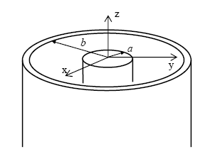
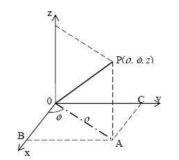
The most commonly used transmission line to guide the electromagnetic wave is the coaxial line. The coaxial line consists of inner and outer conductors and an inner dielectric insulator. As shown in figure 35, a coaxial line has an inner conductor of radius, a, and an outer conductor of inner radius, b, insulated by a dielectric layer of permittivity, e. Figure 36 presents the cylindrical coordinate system for the solution inside coaxial lines.

Figure 35. Diagram. Coaxial line. (11)

Figure 36. Cylindrical coordinate system. (12)
In the cylindrical coordinate system, coordinate r is the distance from the z-axis or length 0A, f is the angle between 0A and the x-axis, and z represents the distance from the x-y plane. The three coordinates, r, f, and z represent the point P and are expressed in terms of unit vectors, ![]() ,
,![]() and
and ![]() .
.
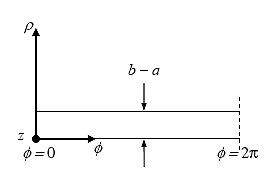
In order to explain the fundamental mode on the coaxial line, it is necessary to consider the case where the inner radius, a, is close to the outer radius, b. When the coaxial line is cut along the x-y plane and unfolded into a parallel strip, the line can be illustrated as figure 33:
7
Figure 37. Diagram. Coaxial line developed into a parallel-plate waveguide. (12)
From Figure 37, it is realized that the wave has the electric field E in the ![]() -direction and the magnetic field H in the
-direction and the magnetic field H in the ![]() -direction and propagates in the
-direction and propagates in the ![]() -direction. Therefore, E and H can be expressed as follows:
-direction. Therefore, E and H can be expressed as follows:
![]() (84)
(84)
![]() (85)
(85)
Where:
| k | = propagation constant, |
| ? | = intrinsic impedance, |
Since the E and H are transverse to the direction of wave propagation, the set of equations 84 and 85 is called the transverse electromagnetic mode (TEM) of the coaxial line.
The following rules are for transforming the field quantities into network parameters. (12)
Rule 1.![]() (86)
(86)
Where:
| a1 | = proportional constant |
| Ct | = integration path transverse to z |
Rule 2.![]() (87)
(87)
Where:
| a2 | = proportional constant |
| C0 | = closed contour of integration |
The power relationship must hold:
Rule 3.![]() (88)
(88)
Where A = cross-sectional area of the line or waveguide
The electric and magnetic fields E and H for a coaxial line in the TEM mode are:
 (89)
(89)
 (90)
(90)
By applying the field equations to the transformation rule, the following equations can be defined as:
 (91)
(91)
 (92)
(92)
Where:
| a1, a2 | = calibration constants |
| V0 | = applied voltage |
| a, b | = inside and outside coaxial transmission line diameters (figure 13) |
If the calibration constants are one (a1= a2 = 1), equations 91 and 92 become:
![]() (93)
(93)
![]() (94)
(94)
Maxwell's equations for electric and magnetic fields can be cast in the standard form of TLEs in terms of voltage and current, V and I, by using cylindrical coordinates. Maxwell's two curl equations are defined as the following TLEs:
![]() (95)
(95)
 (96)
(96)
By eliminating I from equation 95, a wave equation for the voltage V can be obtained as follows:
 (97)
(97)
V has two solutions of ![]() and
and ![]() . Each solution has an integration constant as a multiplier. V can be expressed by introducing two constants, V+ and V-, as:
. Each solution has an integration constant as a multiplier. V can be expressed by introducing two constants, V+ and V-, as:
![]() (98)
(98)
Where ![]()
The amplitude of V+ represents a wave traveling in the positive z-direction and the amplitude of V- represents a wave traveling in the negative z-direction.
| < Previous | Contents | Next >> |