U.S. Department of Transportation
Federal Highway Administration
1200 New Jersey Avenue, SE
Washington, DC 20590
202-366-4000
Federal Highway Administration Research and Technology
Coordinating, Developing, and Delivering Highway Transportation Innovations
 |
| This report is an archived publication and may contain dated technical, contact, and link information |
|
Publication Number: FHWA-HRT-04-150 Date: July 2006 |
Previous | Table of Contents | Next
Usually, the aggregates used in HCC are naturally occurring earth materials that have been crushed, graded, and washed as needed to meet the requirements for the concrete being produced. The amount of beneficiation required will depend on the nature of the aggregate and the requirements of the specifications. Often transporting the aggregate is more costly than obtaining it from the quarry (presumably cleaned and sized). Therefore, aggregate sources near the concrete production plant are often preferred over sources of higher quality material located at a greater distance. The preparation of aggregate specimens for petrographic examination is described briefly in section 5.5.
Not all natural rocks are suitable for use as aggregate, although a wide variety have been successfully used (Mather and Mather, 1991). The material used must pass specific tests as specified in ASTM C 33 and in any specification document provided by the client, customer, or purchaser. In Virginia, the document is Road and Bridge Specifications (Virginia DOT, 2002).
The petrographic description of the aggregate should be guided by ASTM C 125 (standard terminology for concrete) and ASTM C 294 (descriptive nomenclature for aggregates). The procedures given in ASTM C 295 (petrographic examination of aggregates) can be used when a supply of the aggregate is available. Detailed information may be found in ACI 221.1R, Dolar-Mantuani (1983), Forster (1994), Galloway (1994), Mielenz (1994), Meininger (1994), Mullen (1978), Ozol (1978), Price (1978), and Schmitt (1990). Basic texts on petrology, petrography, and mineralogy should be available and familiar to all persons doing this work (see the Reading List). Any person performing petrographic examinations of HCC or aggregates or who is engaged in specifying aggregate properties should carefully study the literature on earth materials and works on concrete aggregates.
The HCC petrographer who generally works with concretes fabricated in a given area, such as a State or group of States, will find that the more familiar he or she becomes with the aggregates from that area, the easier aggregate identification will become. A collection of reference aggregates is very helpful. The aggregates should be identified as to quarry, approximate date quarried, geologic formation, and rock type. The collection should include specimens of concrete containing the aggregate, as well as specimens of the unused aggregate.
The ability of aggregate to withstand the stresses induced during the mixing of HCC is very important and, therefore, aggregates must be able to conform to the abrasion resistance requirements specified in ASTM C 33 (specification for concrete aggregates) as tested in accordance with ASTM C 131 (resistance to degradation of small-size coarse aggregate) or ASTM C 535 (resistance to degradation of large-size coarse aggregate). Commonly, the external characteristics of the aggregate (such as the distribution of the particle sizes, shape, texture, surface coatings, type of fracture, surface area, etc.) are more important to the behavior of aggregates in HCC than is the mineral and chemical composition of the aggregate. Forster (1994) and Galloway (1994) provide excellent explanations of these properties. A summary of some of these testing procedures may be found in ASTM R0030, Manual of Aggregate and Concrete 264 Testing (2002). The fine aggregate (i.e., those passing a No. 4 (4.75-mm) sieve) requires specialized testing (Gaynor and Meininger, 1983).
The particle shape and texture of the aggregates are important characteristics as they can have a significant impact on concrete workability and thus water demand. The particle shape can be evaluated by determining the loose or uncompacted void content by methods such as Virginia Test Method No. 5 (Virginia DOT) or the test method described in Gaynor and Meininger (1983) (subsequently adopted as ASTM C 1252). The preceding methods are specific for use with fine aggregates; however, Hossain, Parker, and Kandhal (2000) report on the development of a similar procedure for coarse aggregates. ASTM C 29 can be used to determine a compacted (by rodding or jigging) or uncompacted (shoveling) void content of coarse or fine aggregate. These tests measure the unforced or forced packability of the aggregate and are thus indirect measurements of the water demand of the aggregate. The void content obtained by these methods is affected by grading, as well as by shape factors, so if one is trying to use the methods to compare the shape of different aggregates, a standard grading must be used. More recently, efforts have focused on developing automated imaging systems to evaluate particle characteristics (Kuo and Freeman, 2000; Masad, Button, and Papagannakis, 2000; Rao and Tutumluer, 2000; Kim, Haas, Rauch, and Browne, 2002; and Rao, Tutumluer, and Kim, 2002).
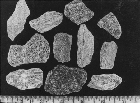
Coarse aggregates (i.e., those retained on a No. 4 (4.75-mm) sieve) for use in HCC are selected mainly on the basis of durability, size, general shape, mineral composition, economy, and availability. Figures 206 and 207 illustrate aggregate particle shapes that are avoided when economic reasons permit.
The requirements of the proposed HCC placement must be fully considered. A placement that has many reinforcing bars close together will require a much smaller coarse aggregate than one with no reinforcement. Pre-placed aggregate is often very large and always lacking in the finer sizes (Lamberton, 1978; Davis, 1994). In particular cases, the density or mineral composition of the aggregate is important. A high density will make it more difficult to prevent segregation; however, the use of aggregate of high density may be dictated by the availability of aggregate or specific use of the concrete. Refer to any specifying document from the client to determine the fitness of a coarse aggregate to meet the requirements of the HCC (see section E.6).
Figure 206. Shaley particle shape of crushed slate aggregate.
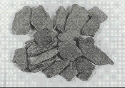
Figure 207. Aggregate particles from a fissile gneiss (a particle shape such as this can cause a high water demand).
Sand (fine aggregate) for use in concrete should be tested for shape and surface smoothness. If the particles have angular shapes with abundant re-entrant angles, the sand has a high void content and a high water demand. It takes more fluid (or cement paste) to surround an angular particle than to surround an equant particle. Among solid shapes, the ratio of the surface area to volume is smallest for spheres and largest for extremely lath-shaped particles and particles with deep re-entrant angles and internal cracks and cavities. If the fluid present is insufficient to coat the surface area, the concrete mixture is harsh and difficult to place and finish. This condition is perceived, during construction, as a need for more water.
It can be difficult to estimate the void content of a fine aggregate from a petrographic examination of a finely lapped slab because the visual contrast between the paste and the sand particles is very low unless the sand is stained or coated. In thin sections, the outline of the sand particles can be easily distinguished from the paste by means of the birefringence of the sand particle. (Very few sand particles have a birefringence as low as that of the paste.) In fluorescent microscopy, where the thin section is impregnated with a fluorescent dye, the outline of the aggregate is emphasized because the aggregate is not illuminated by fluorescence and the porous paste is illuminated. The weak zones caused by high water demand are exceedingly porous, contain very large capillaries, and become brightly illuminated by the fluorescence of the impregnating dye (see figures 168 through 171).
Often a general identification of minerals or rocks present in an aggregate will suffice for routine purposes. Such identifications can be performed on hand samples with simple tools and hand lenses (FHWA, 1991). The same techniques can be used to examine and identify aggregates in polished slabs of concrete. When required, the exact mineralogical identification of natural and artificial aggregates can be accomplished by determining the optical properties by use of the petrographic microscope when the aggregate is examined in grain mount, thin section, or both; by using various methods of determining the chemicals present (spot tests, EDX, XRF); and by collecting an x-ray diffraction pattern for positive identification.
Such identification is necessary only when the distinction between similar rocks might elucidate the reasons for differences in durability or other behavior when the aggregate in question is used in HCC. There are many excellent books written on these methods, and courses on these methods are taught in the materials engineering and geology departments of numerous universities (see the Reading List).
Most often, exact identification is not necessary. Usually, the most detailed examinations are required when AARs are suspected or carbonate rocks are suspected of causing D-cracking (Schwartz, 1987). For more data on alkali-reactive aggregates, refer to chapter 10 and the associated figures and references; the related ASTM standards (Reading List); and the section on thin-section preparation (section 5.2).
Minerals are naturally occurring chemical elements or compounds with well-defined molecular structures. The chemistry and structure of minerals result in their having a unique set of properties that can be used to identify them (table 29). Rock and Mineral Identification for Engineers (Report No. FHWA-HI-91-025) (FHWA, 1991) provides a detailed outline for identifying minerals in hand specimens. These techniques can also be applied in identifying minerals in aggregates in lapped slabs of concrete. In using these characteristics, it can sometimes be misleading to base identification on a single characteristic; a more positive approach is to use the sum of several characteristics. Table 30 provides selected characteristics of common minerals. Figure 208 shows the Mohs scale (a comparative hardness scale).
Figure 209 illustrates the use of crystal habit, color, and luster to identify pyrite in a rock. Cleavage traces can be used to differentiate between feldspars and quartz (minerals of similar hardness) (figure 210). Hardness (figure 211), as well as acid solubility, is used to differentiate between fine-grained limestones and quartzites.
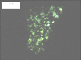
If the optical properties are needed to help in identifying the minerals (or rocks), grain mounts or thin sections can be made for study. Data on the optical properties of minerals can be found in a number of sources (e.g., Larsen and Berman (1964), Winchell and Winchell (1964), Heinrich (1965), and Deer, et al. (1992)). MacKenzie and Guilford (1980) provide excellent photomicrographs of the major rock-forming minerals. The measurement of the refractive index is often useful in distinguishing between minerals of similar characteristics, such as chalcedony (microfibrous silica with a refractive index of 1.537) and quartz (microcrystalline, with a refractive index greater than 1.54), both of which may form chert particles (figures 212 and 213). Figures 214 and 215 show the identification of quartz grains dispersed in a calcic schist.
Using the specimen illustrated in chapter 14, a petrographer may combine information derived from both microscopy and x-ray powder diffraction to identify minerals within an aggregate. The x-ray powder diffraction patterns are unique for each crystalline phase; they are produced independent of each other; and, in a mixture, the pattern intensity is proportional to phase abundance. Qualitative and quantitative analysis of aggregate phase composition may then be made by x-ray powder diffraction (figure 216) with the aggregate being composed of albite (24 percent), anorthite (4 percent), quartz (12 percent), epidote (22 percent), hornblende (19 percent), augite (3 percent), and chlorite (15 percent). The SEM/EDX data on texture and bulk chemistry may then be used to identify the mineral constituents in the aggregate of this pavement (figure 217) where the minerals adjacent to the reaction area are identified as albite ((Na,Ca)Al(Si,Al)3O8) and chlorite ((Mg,Fe)Al3(Si,Al)4O10(OH)2).
|
| Mineral | Hardness | Cleavage | Other |
|---|---|---|---|
| Pyrite | 6 to 6.5 | None | Brassy, fool’s gold; weathers easily to give iron stain; common accessory mineral in many rock types |
| Hematite | 5.5 to 6.5 | None (in massive form) | Red-brown; common accessory in many rocks; cement in many sandstones |
| Magnetite | 6 | None (in granular form) | Black; magnetic; common accessory mineral in many rock types |
| Limonite | 5 to 5.5 | None | Yellow-brown; earthy; may appear softer than 5; formed by alteration of other iron minerals |
| Fluorite | 4 | 1 plane | Common accessory mineral in limestones and dolostones; translucent to transparent |
| Calcite | 3 | 3 planes at 75° | Very common; occurs in many rock types; chief mineral in limestone; vigorous reaction with dilute HCl |
| Dolomite | 3.5 to 4 | 3 planes at 74° | Common; with calcite in dolomitic limestone or dolostone (> 50 percent dolomite); vigorous reaction with dilute HCl only when powdered |
| Apatite | 5 | 1 plane, poor | Common minor accessory mineral in all rock classes |
| Gypsum | 2 | 4 planes, 1 perfect | Common mineral, especially in limestones and shales; may occur in layers |
| Quartz | 7 | None | Silica; very common; may occur in many rock types; glassy; translucent to transparent; may be colored; very resistant to weathering; chief mineral in sandstones |
| Chert | 7 | None | Cryptocrystalline (microscopic crystals) variety of quartz; appears massive to naked eye; common in limestones or in complete layers associated with limestones; light tan to light brown |
| Chalcedony | 7 | none | Microfibrous silica with water inclusions; tan to brown; varieties: flint (dark brown to black), jasper (red), agate (banded) |
| Orthoclase | 6 | 2 planes at 90° | A feldspar; very common in many rock types; white to gray to red-pink; translucent to transparent; distinguished from quartz by cleavage |
| Plagioclase | 6 | 2 planes at 94° | A feldspar; very common in many rock types; appears similar to orthoclase; distinguished by the presence of thin, parallel limes on cleavage faces because of crystal structure (twinning) |
| Olivine | 6.5 to 7 | None | Transparent to translucent; olive green; glassy; common accessory mineral in the darker igneous rocks |
| Garnet | 6.5 to 7.5 | None | Red to red-brown; translucent to transparent; common accessory mineral in metamorphic and some igneous rocks, also in sands and sandstones |
| Zircon | 7.5 | None | Usually colorless to brown; usually translucent; common accessory mineral in igneous rocks and some metamorphic rocks, also in sands and sandstones |
| Pyroxene(group) | 5 to 7 | 2 planes at 87° and 93° | Most common in darker igneous rocks; usually green to black; translucent to transparent; most common mineral: augite |
| Amphibole (group) | 5 to 6 | 2 planes at 56° and 124° | Most common in metamorphic rocks and darker igneous rocks; usually dark green to brown to black; translucent to transparent; most common mineral: hornblende; distinguished from pyroxenes by cleavage |
| Clay minerals(group) | 2 to 2.5 | 1 plane | Usually fine-grained; earthy; often derived from weathering of feldspars; montmorillonite is the swelling clay that expands with the absorption of water; illite is the common clay mineral in many shales |
| Talc | 1 | 1 plane | Very soft; greasy; cleavage may be hard to see because of fineness of particles; commonly white to pale green; usually in metamorphic or altered igneous rocks |
| Serpentine | 2 to 5 (usually 4) | None | Massive to fibrous; greasy to waxy; various shades of green; found in altered igneous or metamorphic rocks; fibrous variety is the source of asbestos |
| Muscovite | 2 to 2.5 | 1 plane | A mica; perfect cleavage allows splitting into thin, clear transparent sheets; usually light yellow to light brown; common in light-colored igneous rocks and metamorphic rocks |
| Biotite | 2.5 to 3 | 1 plane | A mica; perfect cleavage allows splitting into thin smoky transparent sheets; usually dark green to brown to black; found in light- to medium-colored igneous rocks and metamorphic rocks |
| Chlorite | 2 to 2.5 | 1 plane | Similar to micas; usually occurs in small particles so cleavage produces flakes; flakes are flexible, but not elastic as are the micas; usually some shade of green |
Figure 208. Mohs comparative hardness scale.
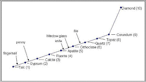
Figure 209. Cubic habit, brassy yellow color, metallic luster of pyrite.
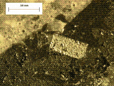
Figure 210. Granite aggregate exhibiting cleavage traces at right angles in orthoclase (right box) and no cleavage in quartz (left box) (scratch test with metal tool leaves metal (arrows) on both quartz and orthoclase, which are harder than the metal).
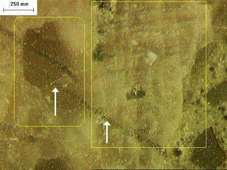
Figure 211. Metal tool scratches upper limestone (calcite) aggregate and leaves metal on lower quartzite particle.
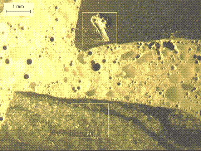
Figure 212. Immersion mount of chert in plane polarized light.

Figure 213. Immersion mount of chert with crossed polars, showing microcrystalline texture (refractive index matches that of quartz).
Note elongated quartz grains (white-gray in right image) set apart from the predominant calcite crystals by their low birefringence and high negative relief. Undulose extinction of quartz (arrow in left image) indicates strain of crystal and suggests increased susceptibility to ASR.
Figure 214. Thin section of marble (calcic schist) in plane polarized light.
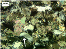
Figure 215. Thin section of marble (calcic schist) in crossed polarized light.
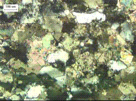
Note elongated quartz grains (white-gray in right image) set apart from the predominant calcite crystals by their low birefringence and high negative relief. Undulose extinction of quartz (arrow in left image) indicates strain of crystal and suggests increased susceptibility to ASR.
Figure 216. Quantitative XRD analysis to determine mineral composition of aggregate shown in figures 182 through 184.
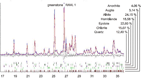
Example XRD composite pattern (plotted with degrees of the angle 2-theta along the horizontal axis) can be used for both qualitative and quantitative analysis.
Figure 217. Coupling the knowledge of the mineral present (figure 216) with the elemental EDX maps shown here allows identification of the minerals present at specific locations within the fine-grained rock.
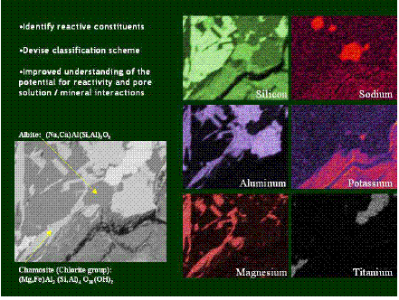
Rocks are assemblages of one or more minerals. They are classified according to their origin, mineralogy (mineral assemblage), and texture (fabric: size, shape, arrangement, and orientation of individual component grains). There are three origin groupings:
Rock and Mineral Identification for Engineers (Report No. FHWA-HI-91-025) (FHWA, 1991) provides a detailed outline for identifying rocks in hand specimens. The key elements to rock identification are given in table 31. Many excellent texts and reference books are available on the identification and classification of rocks. Examples are Pettijohn (1975), Hyndman (1972), and Williams, et al. (1954). However, it is recommended that the nomenclature in ASTM C 294 be used in reports to facilitate communication between the petrographer and engineers.
Classification of igneous rocks is based on grain size and mineral assembly. Grain size is indicative of cooling rate; thus, coarser grains indicate slow cooling at depth (plutonic), whereas very fine crystals or glassy textures indicate rapid cooling of volcanic rocks. The rocks can be broken down into three basic groups based on predominant mineral assemblage:
Table 32 provides a simple classification chart for igneous rocks. Texts should be reviewed for details in classifying igneous rocks (e.g., Hyndman, 1972, Williams, et al., 1954). Coarser grained rocks can usually be adequately classified in hand specimens with the use of lowpowered magnification. If more detail is needed, thin sections can be examined. MacKenzie, Donaldson, and Guilford (1982) provide an excellent collection of photomicrographs of igneous rocks in thin sections.
Sedimentary rocks are grouped into carbonates, classified by calcite-dolomite ratio and noncarbonates. Table 33 provides a simple classification for carbonate rocks. Initial identification of carbonate rocks is accomplished with scratch hardness testing (figure 211) and acid solubility. Acid etching of lapped surfaces will help in differentiating dolomite from calcite in mixtures of the two, as dolomite is less soluble. Because of the fine-grained nature of most carbonates, thin-section examination is often called for. A collection of photomicrographs of carbonate rocks can be found in Adams, et al. (1984). When detailed differentiation between the carbonate minerals is needed, staining with Alizarin Red solutions, followed by examination of the thin section, or an acetate peel are useful (see Heinrich, 1965; Adams, et al., 1984). Many carbonate rocks in the central States are susceptible to D-cracking and various petrographic means for differentiating among them have been developed. These are discussed in section E.5. Alkali-carbonate reactions are discussed in chapter 10and further information on identifying ACR rocks is given in section E.4.4
|
|
| Rock (coarse-grained/ fine-grained) | Minerals (primary) | Minerals (accessory) |
|---|---|---|
| Granite/Rhyolite | Quartz, Orthoclase | Mica, Plagioclase, Pyroxene, Amphibole |
| Trachyte/Syenite | Orthoclase, Plagioclase | Mica, Pyroxene, Amphibole |
| Diorite/Andesite | Plagioclase, Amphibole | Mica, Pyroxene |
| Gabbro, Diabase/ Basalt (Trap) | Plagioclase/Pyroxene | Biotite, Magnetite |
| Peridotite | Pyroxene, Olivine | Magnetite, Chromite |
Noncarbonate rocks are classified based on the size, shape, and composition of the constituent grains. A simple classification scheme is presented in table 34. Thin-section examination may be needed to provide more detailed information about the composition of the rock, in particular, the matrix or cementing material. Adams, MacKenzie, and Guilford (1984) provide a collection of photomicrographs of clastic sedimentary rocks.
| CaCO3 (> 90 percent) | CaCO3 (50 to 90 percent) | CaMg(CO3)2 (50 to 90 percent) | CaMg(CO3)2 (> 90 percent) |
|---|---|---|---|
| Limestone | Dolomitic limestone | Calcitic dolomite | Dolomite |
| HCl: Readily effervescent | Grades toward -> Depends on amount of insoluble material | HCl: Slowly effervescent | |
| Scratched with a knife blade: Relative hardness depends on internal porosity (compactness), nature, and amount of insoluble constituents | |||
| Most contain some component of noncarbonate constituents (e.g., fine quartz, chert, clay (argillaceous material), pyrite, gypsum) | |||
| Texture | Composition | ||
|---|---|---|---|
| Quartz > 90 percent | Quartz < 90 percent of framework grains | ||
| Coarse-grained > 30 percent > 2 mm | Conglomerate Framework grains rounded or Breccia Framework grains angular | ||
| Medium-grained 0.06 to 2 mm | Quartz sandstone | Graywacke (> 25 percent feldspar, dark mica matrix) | Arkose (> 15 percent feldspar, other than dark mica matrix) |
| Fine-grained < 0.06 mm | > 66 percent framework is quartz siltt | Siltstone | |
| > 50 percent clay-sized | Shale or mudstone | ||
The classification of metamorphic rocks is based on composition, grain size, and fabric. They are usually foliated to some degree, but the extent is dependent on the mineral assemblage and the degree of force exerted on the rock. Simple classifications are given in table 35. Details of classification systems can be found in many texts and other reference materials (e.g., Hyndman, 1972; Williams, et al., 1954; Yardley, et al., 1990). Yardley, et al. (1990) provides photomicrographs of the major metamorphic rock types and textures.
| Fine-grained Coarse-grained | Slate: Laminated, parallel cleavage; mineral grains not distinguishable; metamorphosed shale |
| Phyllite: Layered; micaceous minerals distinguishable; metamorphosed argillite | |
| Schist: Thinly layered, nearly parallel cleavage; quartz and feldspar with abundant mica, chlorite, or amphiboles | |
| Gneiss: Foliated; alternating layers of mica, amphiboles with granular quartz and feldspar | |
| Metaquartzite: Metamorphosed quartz sandstone | |
| Metagraywacke: Metamorphosed graywacke | |
| Hornfels: Equigranular; massive; high-temperature alteration by contact metamorphism | |
| Marble: Medium- to coarse-grained carbonate |
ASR is discussed in chapter 10. Aggregate examinations should identify known reactive rock types and the petrographer should look for the presence of reactive constituents (table 36). In some cases (e.g., opal, which may occur as coatings or filling voids), as little as 0.5 percent is sufficient to cause deleterious expansion. These examinations will require preparation of immersion mounts, thin sections, or polished sections, and can be supplemented by XRD (see figures 212 through 218). More detail can be found in ACI 221.1R, ASTM C 295, and other ASR-related references. Van Epps and Erlin (1990) describe a case study of an aggregate with opal coatings.
| Volcanic Glasses | Silica (SiO2) Minerals |
|---|---|
| Felsic (> 66 percent SiO2) | Cristobalite, tridymite Opal Chalcedony |
| Intermediate (> 0 percent SiO2) | Quartz Cryptocrystalline, microcrystalline, strained, granulated |
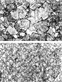
ACRs are described in chapter 10, which discusses the characteristics of susceptible rocks. Because the rocks are fine-grained and texture is an important component in differentiating the expansive rocks, thin-section examinations are invariably called for. Examples of expansive ACR textures are shown in figure 219 and can be compared with the non-expansive textures shown in figure 220. A variety of other methods available for evaluating the potential expansion of ACR rocks are discussed in ACI 221.1R, Ozol (1994), and Famy and Kosmatka (1997).
Figure 218. Thin section of strained quartzite: Crossed polars.
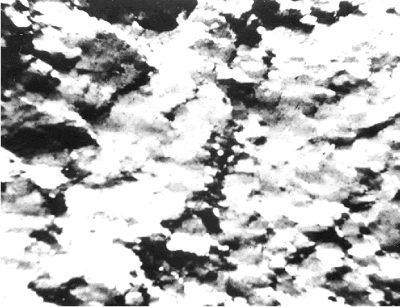
Field is 15 mm across.
Figure 219. Alkali-reactive microtexture in four carbonate rocks.
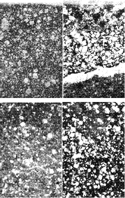
Figure 220. Nonreactive microtextures of carbonate rocks (examples are shown to illustrate the difference between these crystalline textures and the partially crystalline reactive textures shown in figure 219).
D-cracking that is caused by destruction of the aggregate by cycles of freezing and thawing has been well documented in the literature, and much information concerning it can be easily found (Schwartz, 1987). Both the ACR and D-cracking involve dolomitic limestones whose composition includes a large portion of insoluble material. Dolomites involved in D-cracking are thought to have a particular fine pore structure and/or contain a minor amount of iron, strontium, or both, in their crystal structure (Dubberke and Marks, 1987; Schwartz, 1987). A specific pore structure and iron or strontium do not seem to be necessary conditions for ACR. The crack patterns produced by these two reactions are very different. D-cracking deterioration is first evident at the edges and near the joints of a pavement. The cracking is parallel with the joint or edge (see figure 221 and compare with figures 94-95, 97, 103-104, and 106-107). ACR is an expansive chemical reaction with the alkalis, whereas D-cracking is caused by freezing andthawing of moisture in the particles of particular susceptible dolomites and does not involve alkalis.
Regarding D-cracking aggregates, Schwartz (1987) stated:
D-cracking is a form of portland cement deterioration associated primarily with the use of coarse aggregates in the concrete that disintegrate when they become saturated and are subject to repeated cycles of freezing and thawing. It is defined by a characteristic crack pattern that appears at the wearing surface of the pavement as a series of closely spaced fine cracks adjacent and generally parallel to transverse and longitudinal joints and cracks and to the free edges of the pavement (p. 5).
It is generally accepted that pore size is the most important characteristic of coarse aggregate influencing its susceptibility to D-cracking (p. 10).
It is generally agreed that the brand or composition of cement does not significantly influence D-cracking (p. 11).
In Iowa, Dubberke and Marks (1987) found that D-cracking is not necessarily related to the pore structure of the aggregate and came to the conclusion that the incidence of D-cracking is higher with ferroan-dolomite aggregates than with other compositions, and D-cracking may be caused or hastened by a chemical reaction with deicing salts.
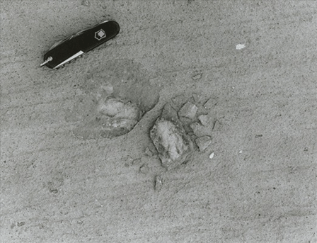
When unsound aggregate particles are situated just below the concrete surface, they can cause popouts (figure 222). Unsound carbonates, shales, and low-density chert particles have been associated with this type of distress (a conical break with the offending particle at the base). ASR of chert and shale particles can also cause popouts.
Figure 221. D-cracking of a pavement caused by destruction of the aggregate by cycles of freezing and thawing (cracking parallel to the joint and wrapping around at the juncture of joints defines D-cracking).
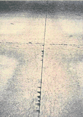
Figure 222. Pavement surface with a flaw caused by freezing and thawing of water trapped in aggregate particle.
Skid resistance is usually desirable for any aggregates used in a surface of HCC that supports traffic. Skid resistance requires that the surface of an HCC pavement be fabricated with hard, nonpolishing aggregates. This generally means that nonsiliceous carbonate rocks cannot be used. In areas where carbonate aggregate is much less expensive than harder aggregate from more distant sources, two-course construction may be the most economic alternative. Not all types of siliceous aggregate provide the same wearing-surface microtexture as others. Despite their hardness, some quartz and feldspar pebbles and quartzitic and granitic rocks may tend to wear with a rounded surface and to polish (see figure 223). Others with particular zones of weakness (e.g., particular granites and graywackes) wear and then break with a microtexture that creates a very skid-resistant wearing surface (see figure 224) (Webb, 1970).
Lightweight aggregates may be specified whenever the weight of conventional aggregates might be a problem. They are frequently used for long-span bridges to alleviate the dead load on the support structures. They may be used when bridge decks require widening and it is considered more economical to widen with the more expensive expanded aggregates than to increase the strength of the support structure.
Figure 223. Traffic-worn rounded surface of feldspar aggregate particle (this will not provide good skid resistance).
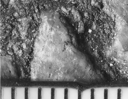
Scale is in millimeters.
Figure 224. Traffic-worn surface of granite aggregate particle (zones of weakness provide an irregular skid-resistant surface).
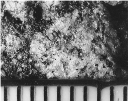
Scale is in millimeters.
Manufactured lightweight aggregates are usually shale or slate that has been expanded by treatment at very high heat. The exterior of the particles becomes fluid, and the gases and vapors inside expand to create a very porous substance with a fused exterior shell. Figure 225 shows this sort of aggregate exposed on a lapped slice of HCC.
Figure 225. Lapped slice of HCC containing expanded-shale lightweight aggregate.
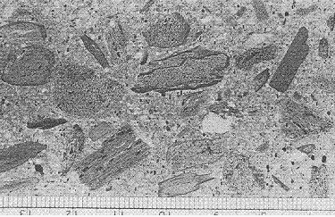
Scale is in millimeters.
These expanded aggregates vary considerably with the source material used and the nature of the heat treatment (temperature, time, oxidation conditions, etc.). Much depends on the depth and continuity of the fused surface of the aggregate particles. If this surface is continuous, the aggregate will have low permeability despite its high porosity.
It is suspected that the chemical composition of the fused layer may have an important effect on the ability of these aggregates to bond with cement paste. Particular expanded aggregate materials produce concretes in which the bond between the aggregate and the paste is extremely good. In other cases, the bond is no better than would be expected of a quartz-pebble aggregate. In examples of a good bond, the aggregate surface does not seem to have an attraction for water, as does quartz and many other highly siliceous materials. These layers of water on the surface of aggregate particles create space along the bond line in the finished concrete that, whether or not it fills with calcium hydroxide, is a zone of weakness in the concrete and a possible channel for water, salt solutions, and other liquid materials. It has been shown that this attraction for water, which lessens the paste-aggregate bond, is most often present in materials that are acidic by nature, whereas the materials that may be considered mafic or alkaline, such as the carbonates and iron-rich minerals,generally have a much tighter bond (Walker, 1972). It has not yet been shown that the chemical composition of the fused layer in expanded aggregate has a direct effect on the properties of the bond. We suspect that such research would probably yield interesting and useful results.
Particular rocks can be used as lightweight aggregates without heat treatment. These may include volcanic ashes, tuffs, and pumices.
Concrete for radiation shielding is designed using heavyweight or special composition aggregates so that the maximum amount of radiation may be contained. These requirements are covered in ASTM C 637 and ASTM C 638. Many of the aggregate minerals used in radiation shielding are opaque, and they cannot be identified with the petrographic microscope. If the exact mineral identification is required, x-ray diffraction and some form of chemical testing or examination with a metallographic microscope will have to be performed.
Adams, A.F.; MacKenzie, W.S.; and Guilford, C. 1984. Atlas of Sedimentary Rocks Under the Microscope. John Wiley and Sons, New York, NY.
American Concrete Institute. ACI 211.1: Standard Practice for Selecting Proportions for Normal, Heavyweight, and Mass Concrete, ACI Manual of Concrete Practice: Part 1, Materials and General Properties of Concrete. Farmington Hills, MI.
American Concrete Institute. ACI 211.2: Standard Practice for Selecting Proportions for Structural Lightweight Concrete, ACI Manual of Concrete Practice: Part 1, Materials and General Properties of Concrete. Farmington Hills, MI.
American Concrete Institute. ACI 221R: Guide for Use of Normal Weight and Heavyweight Aggregates in Concrete. ACI Manual of Concrete Practice: Part 1, Materials and General Properties of Concrete. Farmington Hills, MI.
American Society for Testing and Materials. ASTM C 29: Standard Test Method for Bulk Density (Unit Weight) and Voids in Aggregate, Annual Book of ASTM Standards: Volume 04.02, Concrete and Aggregates. West Conshohocken, PA.
American Society for Testing and Materials. ASTM C 33: Standard Specification for Concrete Aggregates, Annual Book of ASTM Standards: Volume 04.02, Concrete and Aggregates. West Conshohocken, PA.
American Society for Testing and Materials. ASTM C 125: Standard Terminology Relating to Concrete and Concrete Aggregates, Annual Book of ASTM Standards: Volume 04.02, Concrete and Aggregates. West Conshohocken, PA.
American Society for Testing and Materials. ASTM C 131: Standard Test Method for Resistance to Degradation of Small-Size Coarse Aggregate by Abrasion and Impact in the Los Angeles Machine, Annual Book of ASTM Standards: Volume 04.02, Concrete and Aggregates. West Conshohocken, PA.
American Society for Testing and Materials. ASTM C 294: Standard Descriptive Nomenclature for Constituents of Concrete Aggregates, Annual Book of ASTM Standards: Volume 04.02, Concrete and Aggregates. West Conshohocken, PA.
American Society for Testing and Materials. ASTM C 295: Standard Guide for Petrographic Examination of Aggregates for Concrete, Annual Book of ASTM Standards: Volume 04.02, Concrete and Aggregates. West Conshohocken, PA.
American Society for Testing and Materials. ASTM C 330: Standard Specification for Lightweight Aggregates for Structural Concrete, Annual Book of ASTM Standards: Volume 04.02, Concrete and Aggregates. West Conshohocken, PA.
American Society for Testing and Materials. ASTM C 535: Standard Test Method for Resistance to Degradation of Large-Size Coarse Aggregate by Abrasion and Impact in the Los Angeles Machine, Annual Book of ASTM Standards: Volume 04.02, Concrete and Aggregates. West Conshohocken, PA.
American Society for Testing and Materials. ASTM C 637: Standard Specification for Aggregates for Radiation-Shielding Concrete, Annual Book of ASTM Standards: Volume 04.02, Concrete and Aggregates. West Conshohocken, PA.
American Society for Testing and Materials. ASTM C 638: Standard Descriptive Nomenclature of Constituents of Aggregates for Radiation-Shielding Concrete, Annual Book of ASTM Standards: Volume 04.02, Concrete and Aggregates. West Conshohocken, PA.
American Society for Testing and Materials. ASTM R 0030: Manual of Aggregate and Concrete Testing, Annual Book of ASTM Standards: Volume 04.02, Concrete and Aggregates (related material). West Conshohocken, PA.
Davis, R.E. 1994. "Preplaced Aggregate Concrete," Significance of Tests and Properties of Concrete and Concrete-Making Materials, P. Klieger and J.F. Lamond, Eds, Report No. ASTM STP 169C. American Society for Testing and Materials, West Conshohocken, PA, pp. 562-566.
Deer, W.A.; Howie, R.A.; and Zussman, J. 1992. An Introduction to the Rock-Forming Minerals. Longman, Green, and Co., Ltd., London, England.
Dolar-Mantuani, L. 1983. Handbook of Concrete Aggregates. Noyes Publications, Park Ridge, NJ.
Dubberke, W., and Marks, V.J. 1987. "The Relationship of Ferroan Dolomite to Rapid Concrete Deterioration," Transportation Research Record 1110. Transportation Research Board, Washington, DC, pp. 1-10.
Farny, J.A., and Kosmatka, S.H. 1997. Diagnosis and Control of Alkali-Aggregate Reactions in Concrete. Portland Cement Association, Skokie, IL.
Federal Highway Administration. Rock and Mineral Identification for Engineers, Report No. FHWA-HI-91-025. Washington, DC.
Forster, S.W. 1994. "Soundness, Deleterious Substances, and Coatings," Significance of Tests and Properties of Concrete and Concrete-Making Materials, P. Klieger and J.F. Lamond, Eds., Report No. ASTM STP 169C. American Society for Testing and Materials, West Conshohocken, PA, pp. 411-420.
Galloway, J.E. 1994. "Grading, Shape, and Surface Properties," Significance of Tests and Properties of Concrete and Concrete-Making Materials, P. Klieger and J.F. Lamond, Eds., Report No. ASTM STP 169C. American Society for Testing and Materials, West Conshohocken, PA, pp. 401-410.
Gaynor, R.D., and Meininger, R.C. 1983. "Evaluating Concrete Sands," Concrete International, Volume 5, No. 12, pp. 53-60.
Heinrich, E.W. 1965. Microscopic Identification of Minerals. McGraw-Hill, New York, NY.
Hossain, M.S.; Parker, F.; and Kandhal, P. 2000. "Uncompacted Voids and Particle Index Tests for Evaluating Coarse Aggregate," Transportation Research Record No. 1721. Transportation Research Board, Washington, DC, pp. 100-105.
Hyndman, D.W. 1972. Petrology of Igneous and Metamorphic Rocks. McGraw-Hill, New York, NY.
Kim, H.; Haas, C.T.; Rauch, A.F.; and Browne, C. 2002. "Wavelet-Based Three-Dimensional Descriptors of Aggregate Particles," Transportation Research Record No. 1787. Transportation Research Board, Washington, DC, pp. 109-116.
Kuo, C.-Y., and Freeman, R.B. 2000. "Imaging Indices for Quantification of Shape, Angularity, and Surface Texture of Aggregates," Transportation Research Record No. 1721. Transportation Research Board, Washington, DC, pp. 157-165.
Landgren, R. 1994. "Unit Weight, Specific Gravity, Absorption, and Surface Moisture," Significance of Tests and Properties of Concrete and Concrete-Making Materials, P. Klieger and J.F. Lamond, Eds., Report No. ASTM STP 169C. American Society for Testing and Materials, West Conshohocken, PA, pp. 421-428.
Larsen, E.S., and Berman, H. 1964. "The Microscopic Determination of the Non-Opaque Minerals," U.S. Geological Survey Bulletin 848. U.S. Government Printing Office, Washington, DC.
MacKenzie, W.S.; Donaldson, C.H.; and Guilford, C. 1982. Atlas of Igneous Rocks and Their Textures. John Wiley and Sons, New York, NY.
MacKenzie, W.S., and Guilford, C. 1980. Atlas of Rock-Forming Minerals in Thin Section. John Wiley and Sons, New York, NY.
Masad, E.; Button, J.W.; and Papagannakis, T. 2000. "Fine-Aggregate Angularity: Automated Image Analysis Approach," Transportation Research Record 1721. Transportation Research Board, Washington, DC, pp. 66-72.
Mather, K., and Mather, B. 1991. "Aggregates," Centennial Special, Volume 3. Geological Society of America, Boulder, CO, pp. 323-332.
Meininger, R.C. 1994. "Degradation Resistance, Strength, and Related Properties," Significance of Tests and Properties of Concrete and Concrete-Making Materials, P. Klieger and J.F. Lamond, Eds., ASTM STP [Special Technical Publication] 169C. American Society for Testing and Materials, West Conshohocken, PA, pp. 388-400.
Mielenz, R.C. 1994. "Petrographic Examination of Concrete Aggregates," Significance of Tests and Properties of Concrete and Concrete-Making Materials, P. Klieger and J.F. Lamond, Eds., Report No. ASTM STP 169C. American Society for Testing and Materials, West Conshohocken, PA, pp. 342-364.
Mullen, W.G. 1978. "Weight, Density, Absorption and Surface Moisture," Significance of Tests and Properties of Concrete and Concrete-Making Materials, Report No. ASTM STP 169B. American Society for Testing and Materials, West Conshohocken, PA, pp. 629-645.
Ozol, M.A. 1978. "Shape, Surface Texture, Surface Area, and Coatings," Significance of Tests and Properties of Concrete and Concrete-Making Materials, Report No. ASTM STP 169B. American Society for Testing and Materials, West Conshohocken, PA, pp. 584-628.
Ozol, M.A. 1994. "Alkali-Carbonate Rock Reaction," Significance of Tests and Properties of Concrete and Concrete-Making Materials, P. Klieger and J.F. Lamond, Eds., Report No. ASTM STP 169C. American Society for Testing and Materials, West Conshohocken, PA, pp. 372-387.
Pettijohn, F.J. 1975. Sedimentary Rocks. Harper and Row, New York, NY.
Price, W.H. 1978. "Grading," Significance of Tests and Properties of Concrete and Concrete- Making Materials, Report No. ASTM STP 169B. American Society for Testing and Materials, West Conshohocken, PA, pp. 573–583.
Rao, C., and Tutumluer, E. 2000. "Determination of Volume of Aggregates: New Image- Analysis Approach," Transportation Research Record 1721. Transportation Research Board, Washington, DC, pp. 73-80.
Rao, C.; Tutumluer, E.; and Kim, I.T. 2002. "Quantification of Coarse Aggregate Angularity Based on Image Analysis," Transportation Research Record 1787. Transportation Research Board, Washington, DC, pp. 117-124.
Schmitt, J.W. 1990. "Effects of Mica, Aggregate Coatings, and Water-Soluble Impurities on Concrete," Concrete International, Volume 12, No. 12, pp. 54-57.
Schwartz, D.R. 1987. "D-Cracking of Concrete Pavements," NCHRP Synthesis No. 134. Transportation Research Board, Washington, DC.
Stark, D. 1994. "Alkali-Silica Reactions in Concrete," Significance of Tests and Properties of Concrete and Concrete-Making Materials, P. Klieger and J.F. Lamond, Eds., Report No. ASTM STP 169C. American Society for Testing and Materials, West Conshohocken, PA, pp. 365-371.
Van Epps, R.J., and Erlin, B. 1990. "Opal-Coated Aggregates: Investigation and Processing for Use," Petrography Applied to Concrete and Aggregates, Report No. ASTM STP 106. American Society for Testing and Materials, West Conshohocken, PA, pp. 121-128.
Virginia DOT. 2002. Road and Bridge Specifications (revisions scheduled every 4 years). Richmond, VA.
Virginia DOT, Materials Division. Virginia Test Methods Manual (various) (revisions individually, as required). Richmond, VA.
Walker, H.N. 1972. The Stripping of Penetration 85-100 Asphalt From Silicate Aggregate Rocks: A Laboratory Study, Report No. VTRC 71-R29. Virginia Transportation Research Council, Charlottesville, VA.
Webb, J.W. 1970. The Wearing Characteristics of Mineral Aggregates in Highway Pavements, Report No. VTRC 70-R7. Virginia Transportation Research Council, Charlottesville, VA.
Williams, H.; Turner, F.J.; and Gilbert, C.M. 1954. Petrography: An Introduction to the Study of Rocks in Thin Section. Freeman, San Francisco, CA.
Winchell, A.N., and Winchell, H. 1964. The Microscopical Characters of Artificial Inorganic Solid Substances: Optical Properties of Artificial Minerals. Academic Press, New York, NY, and London, England.
Yardley, W.D.; MacKenzie, W.S.; and Guilford, C. 1990. Atlas of Metamorphic Rocks and Their Textures. John Wiley and Sons, New York, NY.