U.S. Department of Transportation
Federal Highway Administration
1200 New Jersey Avenue, SE
Washington, DC 20590
202-366-4000
Federal Highway Administration Research and Technology
Coordinating, Developing, and Delivering Highway Transportation Innovations
 |
| This report is an archived publication and may contain dated technical, contact, and link information |
|
Publication Number: FHWA-HRT-04-150 Date: July 2006 |
Previous | Table of Contents | Next
The use of fluorescence microscopy in the study of HCC was initiated by Wilk, Dobrolubov, and Romer (1974) in Switzerland and was then used mainly as a tool to determine the quality of the air-void system in HCC. Wilk and associates used ultraviolet light transmitted through a thin section. The design of the P/EF, polarizing / epi-fluorescence, microscope makes it possible to view any spot on a thin section with all of the illumination modes of a petrographic microscope,along with incident ultraviolet light, and is thus easily adaptable to this purpose (Walker and Marshall, 1979). All the modes of viewing that are possible with a petrographic microscope were combined with the ability to view the fluorescence (when illuminated by ultraviolet light) within a thin section impregnated with specially dyed epoxy (see section 5.3.4). The design is such that changing the exciter filters by adjusting a turret housing and the dichroic mirrors (DM) by moving a slide across a slot, exchanging barrier filters (BF), and flipping shutters are all that are required to switch from one mode to another. Soeder (1990) used epifluorescence microscopy with a different dye, DM, and BFs to study the pore structure of rocks of low permeability.
It was found that when ultraviolet illumination was transmitted through the thin section, it caused fluorescence of all the fluorescent dye throughout the thickness of the section. The dye was distributed through all the capillary pores, in all the cracks no matter how small, and in all the small voids remaining in the paste as the cement hydrated. The fluorescence existed throughout the thickness of the section and produced a haze of uncollimated light that confused all viewing with a cloud in which any opaque particles (such as cement ferrites) seemed to float. If the section was more than 25 µm in thickness, even some of the air voids would be difficult to distinguish from the background haze. The work of Beauchamp and Williford (1974) and Beauchamp, et al. (1972) indicated that thinner sections would provide more definition. It was determined that the ultraviolet illumination must be incident (come from the direction of the objective, i.e., be what is termed "epi illumination") upon the thin section so that the portion of the specimen being viewed was the first part of the specimen illuminated; thus, the ultraviolet light exciting the most clearly viewed fluorescence was not shaded by other portions of the specimen (Walker and Marshall, 1979).
The question has been asked: Why use a thin section? Why not just use a highly polished slice for this incident light microscopy? After all, that is how one studies ore specimens. The answer is twofold:
The incident arrangement of the ultraviolet illumination necessitated using uncovered thin sections and the type of objective lenses required by uncovered thin sections. The light created within the specimen by the fluorescence of the dye is uncollimated and radiates from every fluorescent point. Such uncollimated light strikes a cover glass at random angles. Only light that strikes a cover slip at 90 degrees to the surface will travel straight through. The light produced at other angles bounces around under the cover slip and from the highly finished surface of the thin section and creates a yellow haze that obscures viewing at all but the lowest magnifications.
Because the incident ultraviolet light is collimated by the objective lens, there is a greater concentration of this light at the point of focus with the higher power lenses (i.e., more ultraviolet light reaches each fluorescent molecule of the dye when the higher power objectives are used). Therefore, the fluorescence is brighter when the higher power objectives are used. At very high magnifications (60X objective), the lens and lens mounting are so close to the specimen that a yellow haze is produced by light bounced from the lens surface to the specimen surface and back, just as when a cover slip is used. This effect precludes the use of oil immersion lenses and lenses of greater power than 40X
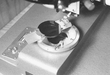
The P/EF microscope is diagrammatically shown in figure 148, and a photograph of the equipment is shown in figure 149 (see Walker, 1988). The P/EF microscope described in this chapter was obtained in 1977 under strict budget requirements. A more modern P/EF microscope that was specifically designed for this use would be more convenient than the model described here. Such a microscope might have different exciter filters, DMs, and BFs built into the instrument and would probably have different engravings for the various filters.
The ultraviolet light is incident on the specimen and is produced by a 200-watt (W) mercury arc lamp. Incident microscope illumination requires a vertical illuminator to direct the light to a special mirror (DM) above the objective lens that will direct the light down through the objective without hindering light traveling from the objective to the ocular. For ultraviolet illumination, the wavelength of the light is controlled by the exciter filters, DMs, and BFs.
The vertical illuminator has a built-in turret for exciter filters:
Figure 148. Light paths and features of the P/EF microscope.
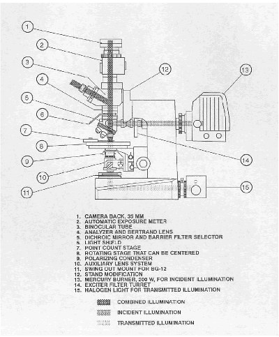
Figure 149. P/EF microscope.
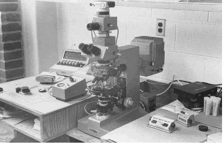
In the right foreground are two pushbutton counters. The camera and exposure meter are on top of the microscope. The control for the exposure meter is between the microscope and the automatic point-counter keyboard in the left background.
For the particular fluorescent dye in use, the exciter filters built into the turret in the vertical illuminator are usually sufficient. The only exciter filters used are the BG-3 (V engraving) and the BG-12 (B engraving). The illuminator has an accessory slot for the insertion of extra filters.Occasionally, it has been convenient to have an extra BG-12 filter for use in the optional exciter filter slot. The only additional BFs used have been a Y-485, a Y-495, and a 0-515. Figure 150 illustrates the relationship of the filters to the dye emittance spectrum. A different dye would have necessitated different filters. To lessen eye fatigue caused by the high contrast, a small amount of transmitted light filtered by a BG-12 filter, 3.0 mm in thickness, is used. A special swing-out mount for this filter was fabricated in the VTRC shop, as illustrated in figure 151.
The transmitted light is from a low-voltage halogen source. The microscope accessories include an automatic point counter, several other pushbutton counters (for counting voids, cracks, and traverses), and a filar micrometer.
The fluorescence elements are used in the study of HCC mainly because much of the paste (especially the hydration products of the cement) is colorless, has a fairly uniform low index of refraction, and has essentially no birefringence. In addition, the paste is a porous material wherein the internal (capillary) porosity is submicroscopic in size. The optical properties of the paste have a tendency to render it featureless and thus difficult to distinguish from empty space. The ability to distinguish empty space from colorless substances with zero birefringence is the major reason the fluorescence is such a useful complement to the microscopist’ s repertory of determinative methods. Included in the apparent empty space are those areas that contained water or air before the drying and vacuum impregnation of the concrete specimen with the dyed epoxy. Such features include cracks in both the aggregate and the paste, the porosity of the aggregate, and the capillary system of the paste.
With this one microscope, the microscopist, while examining one particular area, can switch back and forth between the fluorescence features and the polarizing features (plane polarized illumination and crossed nicols); thus, it is possible to detect and assess areas of empty space and define their relationship to the reaction products, minerals, rock types, coatings and shapes of the aggregate particles, and other components of the concrete. A feature not readily recognizable in one mode can be easily examined in another. The aggregates, secondary mineralization, and reaction products can be identified and studied with the polarizing capabilities, whereas the areas of empty space and their distinction from some of the hydration products can be determined best by use of the fluorescence of the spaces impregnated by the dyed epoxy.
Figure 150. Relationship of filters to dye emittance spectrum.
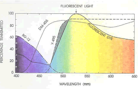
Percentage transmittance of exciter filters, dichroic mirrors, and barrier filters of a microscope compared with the excitation spectrum of fluorescent dye.
Figure 151. Swing-out filter over light port on base of microscope.
Filter holder was fabricated in the VTRC shop.
There are seven main uses of the P/EF microscope: cracks, air-void parameters, porosity related to carbonation, w/cm and permeability, hydration, effect of fine aggregate, and photomicrographs.
Because the impregnation with the fluorescent dye precedes the thinning of the section to the point that will create new cracks in the aggregate, it is possible to know whether a particular crack (such as a cleavage crack in aggregate) was indigenous to the specimen or was caused by the processes used in the thinning of the section. If the crack is filled with the fluorescent dye,the crack preceded thinning and can be assumed to be a feature of the specimen that was present before it came to the laboratory.
In concrete, the cracks may go in any direction and often skirt the edges of the aggregate particles. Even if the thin section is very thin, there may be no direct path along a crack for transmitted light to come through (see figure 152). The fluorescence of the impregnating epoxy mixture creates light within all the cracks. Even those cracks whose width is below the resolving power of the lenses used may be detected and their location identified. Because of the uncollimated nature of this fluorescent light, the apparent width of these very fine cracks is somewhat increased.
Figure 152. Cracks in the thin section of the concrete.
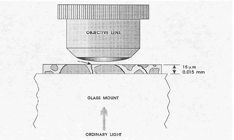
The arrow indicates the only crack that would be visible with transmitted illumination. Impregnation with a fluorescent dye and illumination with ultraviolet light would make possible the observation of the fluorescence of the dye in the other cracks. (The supporting glass slide would be about 100 times the thickness of the thin section of the concrete.)
For laboratory-produced concrete examined at a moderate magnification of about 200X, it was found that air-content determinations made on two thin sections of HCC (more were considered too costly) by the fluorescence method had no correlation with the air-content determinations made on a finely lapped slice of the concrete by the linear traverse method of ASTM C 457 even though great care was taken to focus on the edges of the voids (see Walker, 1979). Although there was no correlation in the air-void determinations, a good correlation was found with the determinations of the specific surface and spacing factor. In the original work done by Wilk, et al. (1974), the spacing factor was considered to be the most important parameter to be determined. Because the Virginia specifications for air content are in terms of percentage of air voids, it was decided that this technique did not fill the needs of the Virginia DOT.
The carbonation reaction results in a densification of the paste (the products occupy a smaller volume than the reactants). The product mineral, calcite, is relatively insoluble in pore solution and its presence results in a permanent reduction in the capillary porosity of the paste. Consequently, less dyed epoxy will penetrate into these areas, and they will exhibit lower fluorescence compared to the uncarbonated areas of the same concrete. If the carbonation is extensive, some cracking may develop in response to the accompanying shrinkage. Such cracks will be highlighted by the fluorescence
The capillary porosity (permeability) of the paste is directly affected by the w/cm. As a consequence, less epoxy penetrates into lower w/cm pastes than higher w/cm pastes, and the degree of fluorescence is lower. The degree of hydration and the type(s) of cementitious materials present affect paste permeability and thus the determination of w/cm by this method.Jakobsen, Laugesen, and Thaulow (2000) discuss in detail the use of this method to determine the w/cm.
The optical properties of the cement and the empty space in and near a cement grain when compared with similar properties of cement grains of known age and similar size and history will indicate the approximate age and degree of hydration of the cement. Because of the much higher resolving power of the SEM, the SEM is very useful for evaluating the extent of hydration of cementitious materials (see chapter 14).
A smooth-surfaced, sound, fine aggregate (few reentrant angles, low porosity, and cracks) will produce a concrete mixture that is easy to finish without additional water. An irregularly shaped or porous fine aggregate will create a harsh mixture with a high water demand and prompt the contractor to add more water (see appendix C, Walker, 1988). Because of the additional water,the concrete may have low strength. The irregular shape and porosity of the sand particles,pockets of excess water, and concomitant clumped distribution of the cement particles may be observed with the P/EF microscope.
Photographing the views seen is very useful for demonstrating to a client the characteristics of the concrete specimen. The photographs taken have also been useful in explaining the problems that can occur with particular materials, such as sand with a high void content or high internal porosity.
There are three important general points with regard to examination with the P/EF microscope:
Figure 153. Fluorescence from porous clay pocket shining through edge of quartz particle.
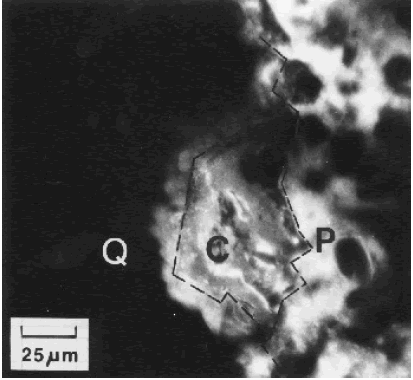
P = paste, C = clay pocket, Q = quartz aggregate; focus plane is within the section (Walker, 1981)
Figure 154. Void in thin section with focus plane on top surface of section.
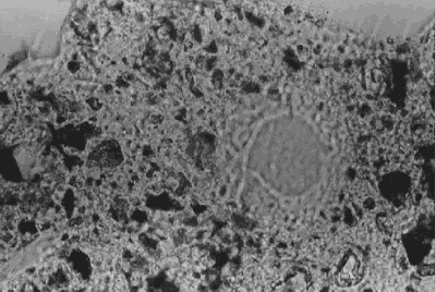
Figure 155. Void in thin section (same as figure 154) with focus plane at bottom of section, 100X.
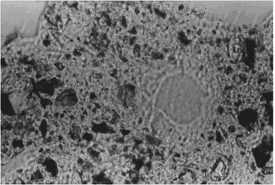
The examination of cracks is a three-step procedure:
The examination of air-void parameters is a seven-step procedure:
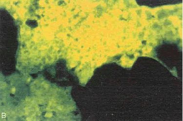
Study the degree of carbonation and the consequences to the integrity of the HCC by switching back and forth between the polarizing and fluorescence features of the microscope as shown in figures 156 through 160. Figures 156 through 158 show that carbonation on the exterior of the HCC can provide a tighter, less permeable structure than exists below the carbonation.Figures 159 and 160 show the high porosity that is often associated with and is likely the cause of carbonation in the interior of the HCC.
The examination for permeability is a two-step procedure:
Similar evaluations can be made using the standard petrographic microscope (chapter 12) if the thin section has been impregnated with a colored (usually blue) epoxy. Liu and Khan (2000) discuss the use of this technique in conjunction with the standard techniques mentioned in chapter 9.
Figure 156. Thin section of exterior portion of the HCC:(A) Surface exposed to the air is at the top.
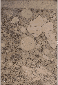
Figure 157. Same view as figure 156, but viewed with crossed nicols: (B) Bright area shows the high birefringence of the calcite of the carbonated area.
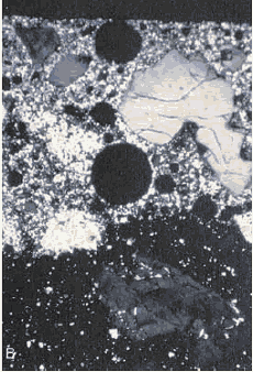
Figure 158. Same view as figures 156 and 157, but (C) viewed with ultraviolet light, causing fluorescence of the pore structure of the HCC (note that there is more porosity indicated by fluorescence in the portion of the HCC farthest from the surface than there is in the carbonated zone).
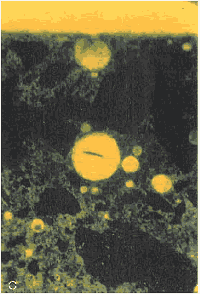
Figure 159. Thin section of interior portion of HCC: (A) Viewed with crossed nicols (bright area shows the high birefringence of the calcite of the carbonated area).Figure 160. Thin section of interior portion of HCC: Same area as figure 159, but (B) viewed with ultraviolet light, causing fluorescence of the pore structure within the carbonated area.
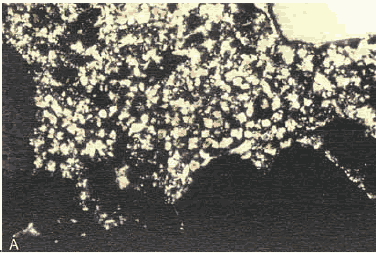
Figure 160. Thin section of interior portion of HCC: Same area as figure 159, but (B) viewed with ultraviolet light, causing fluorescence of the pore structure within the carbonated area.
The examination for hydration is a two-step process:
Figure 161. Thin section of 50-yearold concrete. (A) At the center is the remnant of a very large cement grain (cement was more coarsely ground then). Modern cement is usually about the size of the completely hydrated and filled cement grain indicated by the arrow (viewed with plane polarized illumination).
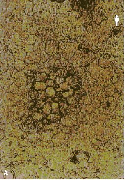
Figure 162. Same location as figure 161, but (B) viewed with crossed nicols. Note the original birefringence still present in the unhydrated central portion of the grain.
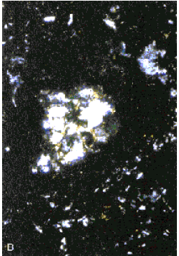
Figure 163. Same location as figure 161, but (C) viewed with ultraviolet light, causing fluorescence of the dye in the pore structure. The structure indicates that the original external boundary of the cement grain was the thin line (indicated by the arrows).
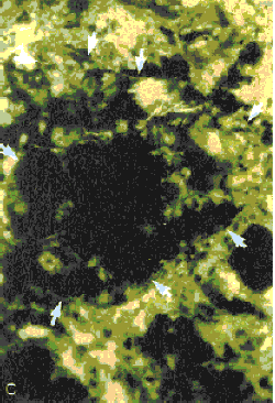
Figure 164. Thin section of 25-year-old concrete viewed with plane polarized light.
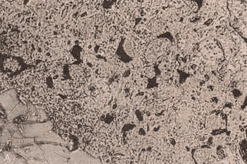
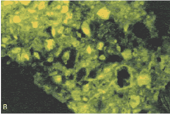
The cement grains are completely hydrated. Some cement grain centers are empty, others contain secondary mineralization.
Figure 165. Thin section of 25-year-old concrete viewed with incident ultraviolet illumination, causing fluorescence of the dye-filled space.
The examination of the fine aggregate is a four-step process:
Five points are important in making photomicrographs:
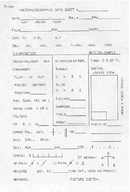
Figure 172 is a page in the P/EF photomicroscopy notebook used at VTRC. The information to be recorded will depend on the nature of the specimen, camera, illumination, and adjustments on the light meter or shutter control.
Figure 166. Thin section of HCC made with smooth, rounded sand:Viewed with plane polarized light.
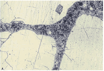
Figure 167. Thin section of HCC made with smooth, rounded sand: Same view as figure 166, but with ultraviolet illumination, causing fluorescence in the pore structure impregnated with dye (note the even texture of the paste).
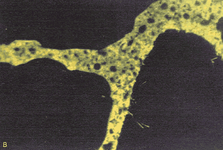
Figure 168. Thin section of HCC made with angular, dirty sand: (A) Viewed with plane polarized light (there are numerous reentrant angles).
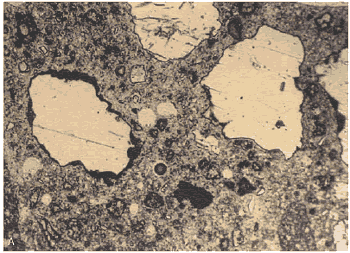
Figure 169. Thin section of HCC made with angular, dirty sand: Same view as figure 168, but (B) with ultraviolet illumination, causing fluorescence that delineates the pore structure.
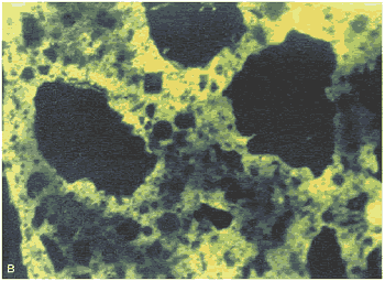
Note the clumping of the cement grains, abundance of pores (shown by the fluorescence) at the edge of the sand, structure of the clay coatings, and general uneven texture of the paste. Such uneven texture indicates zones of weakness through the HCC.
Figure 170. Thin section of porous, iron-stained particle of sand: Viewed with plane polarized light.
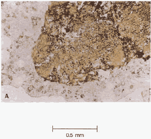
Figure 171. Thin section of porous, iron-stained particle of sand: Viewed with incident ultraviolet illumination, causing fluorescence of the dye in the pore structure of the sand grain and indicating a zone of water accumulation and weakness.
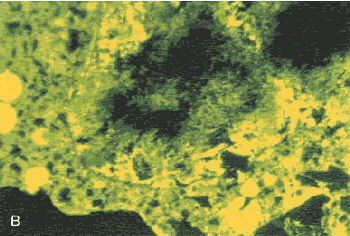
Figure 172. Page from VTRC P/EF photomicroscopy notebook.
