U.S. Department of Transportation
Federal Highway Administration
1200 New Jersey Avenue, SE
Washington, DC 20590
202-366-4000
Federal Highway Administration Research and Technology
Coordinating, Developing, and Delivering Highway Transportation Innovations
 |
| This report is an archived publication and may contain dated technical, contact, and link information |
|
Publication Number: FHWA-HRT-05-081 Date: October 2005 |
Previous | Table of Contents | Next
The Virginia Department of Transportation planned to construct a steel-reinforced CRCP on S.R. 288 in June 2003.(12) The CRCP would consist of two lanes: one 4.267-m-(14-ft-) wide travel lane, and a 3.658-m- (12-ft-) wide passing lane. The CRCP section is 25.4 cm (10 inch) thick, and it is reinforced with a steel reinforcing ratio of about 0.74 percent, which corresponds to number 6 longitudinal reinforcements spaced at 15.24 cm (6 inches). Number 5 steel rebars were used for the transverse reinforcement at a spacing of 121.9 cm (48 inches). Below the pavement section is a 7.62-cm- (3-inch-) thick asphalt-stabilized open graded drainage layer (OGDL; number 57 AASHTO gradation, treated with 2.5 percent asphalt by weight), which is then supported by a 15.24-cm- (6-inch-) thick layer of cement-treated aggregate (dense aggregate type I, size 21A, treated with 4 percent cement by weight). The coarse aggregate of metamorphosed granite is used for concrete mix. The design parameters and material properties of the VDOT's CRCP are listed in table 5; the table also includes the GFRP material properties and the assumed bond property between concrete and subbase for the following mechanistic study of a GFRP-reinforced CRCP.
The performance of the steel-reinforced CRCP at 28 d in terms of crack spacing, crack width, and tensile stress level in steel reinforcement at crack was predicted by using the mechanistic analysis program, CRCP8.(22) A mean crack spacing of 1.058 m (3.47 ft), a crack width of 0.49 mm (0.0193 inch),and a reinforcement tensile stress at crack of 288.56 MPa (41.850 ksi) were obtained. The crack spacing is acceptable even though the crack spacing of1.058 m (3.47 ft) barely meets its allowable lower limit of 1.067 m (3.5 ft) since the punchout failure, which is first characterized by a loss of aggregate interlock at one or two closely spaced cracks (usually less than 0.610 m (2 ft)), can be avoided provided that the crack width is narrow enough (≤1 mm (0.04 inch)).(2,10) Also, the steel reinforcement stress at crack is lower than its maximum allowable limit of 379 MPa (55 ksi), which is about 75 percent of the ultimate tensile strength for the grade 60 number 6 steel rebar.(2)
In the following section, based on the design parameters and material properties of VDOT's CRCP (table 5), except for replacing number 6 steel reinforcement with number 6 GFRP reinforcement, the performance of GFRP-reinforced CRCP will be predicted over various types of concrete and subbase. This mechanistic prediction shows the effect of using different types of concretes and subbase's on the pavement's performance, which the FE analysis previously conducted could not explicitly indicate. In addition, the performance of the GFRP-CRCP will be compared with that of the steel-CRCP in this chapter. The ideal situation is to come up with a feasible GFRP-CRCP design that performs comparable to the steel-CRCP without raising the GFRP reinforcement ratio. Considered in the mechanistic simulation of GFRP-CRCP is also the same GFRP rebar properties utilized in the FE analysis in Chapter 5.
| Parameters and Properties1 | Value |
|---|---|
| Longitudinal reinforcement spacing (cm (inches)) | 15.24 (6.0) |
| Pavement thickness (cm (inches)) | 25.4 (10.0) |
| Young's modulus of concrete at 28 d (GPa (x 106 lbf/in2)) | 31.44 (4.56) |
| Compressive strength of concrete at 28 d (MPa (lbf/in2)) | 32.13 (4,660) |
| Tensile strength of concrete at 28 d (MPa (lbf/in2)) | 3.86 (560) |
| Total shrinkage of concrete ( |
394 |
| Young's modulus of steel rebar (GPa (x 106 lbf/in2)) | 200.00 (29) |
| Longitudinal Young's modulus of GFRP rebar (GPa (x 106 lbf/in2)) | 41.37 (6.0) ( |
| Ultimate tensile strength of GFRP rebar (MPa (ksi)) | 620 (90) |
| CTE of concrete, |
10.33 (5.74) |
| CTE of steel rebar, |
11.88 (6.6) |
| CTE of GFRP rebar, |
9.07 (5.04) |
| Bond-slip stiffness/unit area bet. concrete and subbase (MPa/m (lbf/in2/inch)) | 15.17 (55.88) |
| Curing, minimum temperature (°C (°F)) | 43.3 (110), -3.89 (25) |
| Static single wheel load (kg (lb)), wheel base radius (cm (inches)) | 4,540 (10,000), 15.24 (6.0) |
1Granite aggregate is used for concrete mix; number rebar is considered; asphalt-stabilized subbase is used.
The material properties of concrete (such as CTE and Young's modulus) are primarily a function of the type of coarse aggregate, and since these properties are interdependent, a consistent set of properties that are representative of the concrete mixture to be used should be carefully selected for the concrete pavement design and analysis.(30) The approximate sets of concrete material properties are listed in table 6. Except for that of granite concrete, the compressive strengths are assumed to be 31.03 MPa (4,500 lbf/in2) to approximate the values of indirect tensile strength, followed by the flexural strength and drying shrinkage values. The concrete material properties and their approximate relationship have been identified by other researchers.(30) In table 6, it is shown that the coarse aggregate types are listed in order of lowest to highest concrete CTE, which are 6.84 ![]() /°C (3.8
/°C (3.8 ![]() /° F) for limestone concrete and 14.40
/° F) for limestone concrete and 14.40 ![]() /°C (8.0
/°C (8.0 ![]() /°F) for siliceous river gravel concrete, respectively.
/°F) for siliceous river gravel concrete, respectively.
| Coarse Aggregate Type | Coefficient of Thermal Expansion ( |
Compressive Strength (lbf/in22) | Young's Modulus (x 106 lbf/in2) | Tensile Strength (lbf/in2) | Flexural Strength (lbf/in2) | Drying Shrinkage ( |
|---|---|---|---|---|---|---|
| Limestone | 3.8 | 4,500 | 3.6 | 387 | 625 | 626 |
| Basalt | 4.8 | 4,500 | 3.8 | 486 | 992 | 471 |
| Granite | 5.74 | 4,660 | 4.56 | 560 | 610 | 394 |
| Dolomite | 5.9 | 4,500 | 4.8 | 495 | 895 | 458 |
| Sandstone | 6.5 | 4,500 | 3.8 | 468 | 762 | 498 |
| Quartz | 6.6 | 4,500 | 4.5 | 495 | 868 | 458 |
| Siliceous River Gravel | 8.0 | 4,500 | 5.0 | 419 | 697 | 572 |
1 1 ![]() /°F = 1.80
/°F = 1.80 ![]() /°C.
/°C.
2 1 lbf/in2 = 0.00689 MPa.
Figure 62 shows the prediction of mean crack spacing for the GFRP-CRCP over various types of concrete coarse aggregate as well as that for the steel-GFRP with granite coarse aggregate, which is the VDOT's CRCP. It can be easily understood that the GFRP-CRCP with granite concrete has larger crack spacing (2.115 m (6.94 ft)) than does the VDOT's steel-CRCP (1.058 m (3.47 ft)) since the Young's modulus of GFRP is smaller than that of steel. Among the GFRP-CRCPs, the CRCP using basalt concrete is predicted to have the largest crack spacing of 2.457 m (8.06 ft), which slightly exceeds the upper limit of allowable crack spacing of 2.438 m (8 ft). This is reasonable since the basalt concrete has a relatively low CTE and Young's modulus, which cause low tensile stress development in concrete and result in less cracks in the CRCP.On the other hand, using the siliceous river gravel concrete creates the smallest crack spacing of 1.003 m (3.29 ft), which results from its high CTE, high Young's modulus, and large shrinkage; this is still acceptable, despite slightly deviating from the lower allowable limit of 1.067 m(3.5 ft) for reasons discussed at the beginning of this chapter.
It is found in the prediction that even though the limestone concrete has the lowest CTE and Young's modulus, the crack spacing is smaller than those for the basalt,granite, dolomite, and quartz concretes (a result of this type having the lowest tensile strength and largest shrinkage). It can therefore be understood that the material properties of each type of concrete must be collectively considered and used in the CRCP design. From the comparison in crack spacing between the GFRP-CRCPs and VDOT's steel-CRCP, it is also found that the GFRP-CRCPs using the sandstone and the siliceous river gravel concretes have crackbrains comparable to that for VDOT's steel-CRCP without increasing the amount of GFRP reinforcement. In addition to the comparable GFRP-CRCPs,the GFRP-CRCP using the limestone concrete has a crack spacing of 1.814 m (5.95 ft), which is within the acceptable range for the criteria of crack spacing.
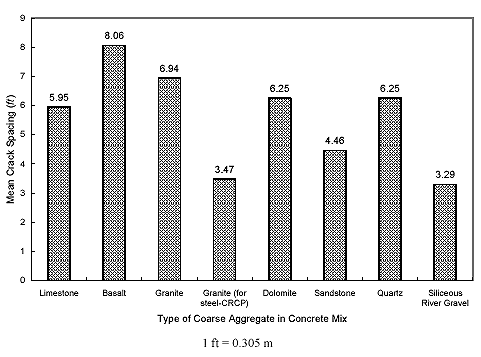
Figure 62. Graph. Mean crack spacing versus type of coarse aggregate in concrete mix (ρ = 0.0074; asphalt-stabilized subbase).
In figure 63, the crack widths were predicted and compared over various concrete coarse aggregate types. In general, the crack widths appear to be wider as their corresponding crack spacings are larger. Also, a larger volume change in concrete appears to contribute to developing a wider crack width. The comparison in crack widths between the limestone and siliceous river gravel cases shows that the crack width for the limestone case, 0.54 mm (0.0211 inch), is narrower than that for the siliceous river gravel case, 0.67 mm (0.0263 inch), although the crack spacing for the limestone case, 1.814 m (5.95 ft), is larger than that for the siliceous river gravel case, 1.003 m (3.29 ft). This can be explained by considering the much larger concrete volume change of siliceous river gravel concrete, which is mainly induced by its much higher CTE. The same explanation can be applied to the comparison between the dolomite and quartz cases.
Among all crack widths which meet the maximum limiting criteria of ≤ 1 mm (0.04 inch), the crack widths for the limestone, sandstone, and siliceous river gravel cases can provide a reliable concrete aggregate interlock at crack. In addition, tighter cracks can be generally expected with the steel reinforcement, since the steel reinforcement (having a higher Young's modulus) can better restrain the concrete volume change and hold the crack more tightly.
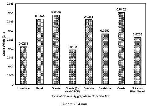
Figure 63. Graph. Crack width versus type of coarse aggregate in concrete mix (ρ = 0.0074; asphalt-stabilized subbase).
Figure 64 shows the tensile stress level in reinforcement at crack for various types of concrete coarse aggregate. The tensile stress levels in GFRP reinforcement are in the range of about 137.90 to 172.38 MPa (20 to 25 ksi), levels that are somewhat higher than the GFRP rebar's allowable tensile stress limit of 124 MPa (18 ksi), which is about 20 percent of its ultimate tensile strength under a harsh environment; this adverse result could be resolved by using a new type of GFRP rebar such as alkaline-resistant GFRP rebar (such as AdvantexTM glass GFRP) which has an allowable stress limit that can be higher than 20 percent.(26) The stress levels in GFRP reinforcement appear to correlate with their corresponding crack widths. In the case of steel-CRCP, the reinforcement stress level is 288.56 MPa (41.850 ksi), which is lower than its limit of 379 MPa (55 ksi) and about 75 percent of the ultimate tensile strength of steel rebar.(2) The higher reinforcement stress for steel-CRCP is attributed to the higher Young's modulus of steel.
From the results, any of the GFRP-CRCPs with the limestone, sandstone, and siliceous river gravel concrete seems to perform satisfactorily without raising the reinforcement ratio under the given conditions provided by VDOT design data. In addition,even though the results show that the GFRP-CRCP with the granite concrete can satisfy the limiting criteria, one may still want to increase the reinforcement ratio to avoid the possibility of violating the limiting criteria due to environmental variations.
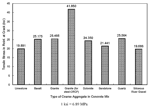
Figure 64. Graph. Tensile stress in reinforcement at crack versus type of coarse aggregate in concrete mix (ρ = 0.0074; asphalt-stabilized subbase).
The comparison of the performances of GFRP-reinforced CRCP on various subbase types was simulated in this section. The linear bond-slip relationships between the concrete slabs and various subbase types, in terms of bond-slip stiffness per unit area of slab base (GPa/m (lbf/in2/inch)), were utilized for the simulation; the relationships were obtained experimentally by a group of researchers at the University of Texas.(33,34,35) The subbase types considered are untreated clay, asphalt stabilized, flexible, lime-treated clay, and cement stabilized,listed in order of lowest to highest bond-slip stiffness/unit area (GPa/m(lbf/in2/inch)). The value of bond-slip stiffness/unit area for each type is shown in table 7. In addition to the cases of the aforementioned subbase types, hypothetical bond-slip cases of 0.136, 0.271, 0.543, 1.357, and2.715 GPa/m (500, 1,000, 2,000, 5,000, and 10,000 lbf/in2/inch,respectively) were also simulated to find the appropriate range of bond-slip for the considered CRCP that eventually satisfies the limit of crack spacing,crack width, and the reinforcement stress level at crack. Granite aggregate concrete was used in this simulation based on material properties listed in table5.
Table 7 and figure 65show the predicted mean crack spacing and crack width over the bond-slip stiffness/unit area. It can be seen from figure 65 that the higher bond-slip results in smaller crack spacing, which in turn causes narrower crack widths.This result is reasonable since the higher bond-slip from the subbase provides the concrete slab with more restraint, causing higher tensile concrete stress under the concrete shrinkage and temperature drop and thus creating more crack sin a certain length of the slab.
| Subbase Type1 | Bond-Slip Stiffness/Unit Area (lbf/in2/inch) | Mean Crack Spacing (ft) | Crack Width (inch) | Reinf. Tensile Stress at Crack (ksi) |
|---|---|---|---|---|
| Untreated clay | 21.95 | 8.62 | 0.0478 | 28.501 |
| Asphalt stabilized | 55.88 | 6.94 | 0.0388 | 25.466 |
| Flexible | 145.45 | 6.94 | 0.0388 | 25.468 |
| Lime-treated clay | 154.55 | 6.76 | 0.0378 | 24.769 |
| ~ | 500 | 5.95 | 0.0334 | 23.255 |
| ~ | 1,000 | 5.68 | 0.0318 | 22.893 |
| ~ | 2,000 | 4.64 | 0.026 | 20.887 |
| ~ | 5,000 | 3.57 | 0.0201 | 18.256 |
| ~ | 10,000 | 2.91 | 0.0164 | 16.250 |
| Cement stabilized | 15,400 | 2.45 | 0.0139 | 14.871 |
1Granite aggregate is used for concrete mix; number 6GFRP rebar is considered.
1 lbf/in2/inch= 0.271 MPa/m; 1 ft = 0.305 m; 1 inch = 25.4 mm; 1 ksi = 6.89 MPa
In the prediction, the asphalt-stabilized subbase results in a mean crack spacing of 2.115 m (6.94 ft) and a crack width of 0.99 mm (0.0388 inch); these results are on the verge of the upper limit. Therefore, the asphalt-stabilized subbase appears to approximately provide the minimum allowable bond-slip (15.169 MPa/m (55.88 lbf/in2/inch)) necessary to avoid spalling distress of the given CRCP. The cement-stabilized subbase was found to have nearly the maximum allowable bond-slip, resulting in a mean crack spacing of0.747 m (2.45 ft) and a crack width of 0.35 mm (0.0139 inch).The mean crack spacing for the cement-stabilized subbase is somewhat small compared with its limit of about 1.067 m (3.5 ft), having the possibility of punchout distress.
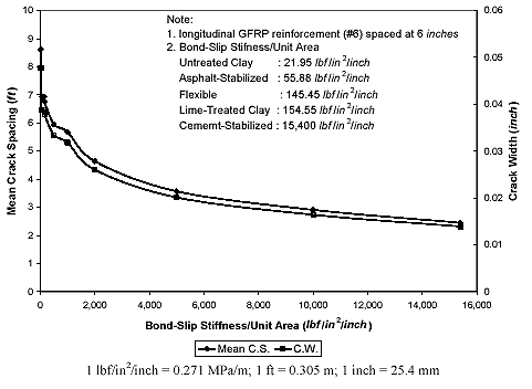
Figure 65. Graph. Mean crack spacing and crack width versus bond-slip stiffness/unit area (ρ = 0.0074; granite aggregate concrete).
The tensile stresses in the GFRP reinforcement at cracks were also predicted over various subbase types (figure 66). As can be seen in the figure, higher bond-slip causes lower tensile stress in the reinforcement at the crack since the smaller crack spacing is expected with the higher bond-slip. The tensile stresses in the reinforcement corresponding to the subbase types range from about 103.43 to 199.96 MPa (15 to 29 ksi). The tensile stress levels for most subbase types, except for that of the cement-stabilized, exceed the allowable tensile stress of 124 MPa (18 ksi).The allowable tensile stress, as can be seen from the figure, is attained at bond-slip of about 1.357 GPa/m (5,000 lbf/in2/inch). Therefore, in order to avoid both spalling distress and early failure of GFRP reinforcement in the CRCP, the bond-slip should be held by at least 1.357 GPa/m (5,000 lbf/in2/inch).Only the cement-stabilized subbase meets this criterion, even though it may have some possibility of causing punchout distress in the CRCP. In this simulation calculated by the CRCP8 program, the bond stress between the concrete and reinforcement leads to stress changes in the concrete and reinforcement, and the bond stress varies in the bond development zone; the location of this zone is determined by solving the system of governing equations with the assumed bond stress distribution function and the reinforcement boundary condition.(3)
The performance of the GFRP-CRCP design presumably proposed by FE analysis in chapter 5 was also mechanistically examined by CRCP8. Since the design was established with the limestone concrete with a compressive strength, fc′, of 27.58 MPa (4,000 psi), the concrete material properties become a little different from those shown in table 6, which are based on fc′ = 31.03 MPa (4,500 psi). The concrete material properties of tensile strength, flexural strength, and drying shrinkage change to 2.37 MPa (344 psi), 3.83 MPa (556 psi), and 712 me, respectively. However, the CTE of 6.84 ![]() /°C (3.8
/°C (3.8 ![]() /°F) and Young's modulus of 24.8 GPa (3.6 x 10⁶ lbf/in2) are assumed to remain the same when fc′ = 27.58 MPa (4,000 lbf/in2). The temperature input for the mechanistic exam also remains the same as that in table 6. This proposed GFRP-CRCP, which is designed utilizing a flexible subbase (or lime-treated clay subbase), is predicted to create a mean crack spacing of 1.466 m (4.81 ft), a crack width of 0.44 mm (0.0173 inch), and a reinforcement tensile stress at crack of 123.93 MPa (17.974 ksi). All of the results appear to be within their own limits and, therefore, the proposed GFRP-CRCP is expected to perform successfully.
/°F) and Young's modulus of 24.8 GPa (3.6 x 10⁶ lbf/in2) are assumed to remain the same when fc′ = 27.58 MPa (4,000 lbf/in2). The temperature input for the mechanistic exam also remains the same as that in table 6. This proposed GFRP-CRCP, which is designed utilizing a flexible subbase (or lime-treated clay subbase), is predicted to create a mean crack spacing of 1.466 m (4.81 ft), a crack width of 0.44 mm (0.0173 inch), and a reinforcement tensile stress at crack of 123.93 MPa (17.974 ksi). All of the results appear to be within their own limits and, therefore, the proposed GFRP-CRCP is expected to perform successfully.
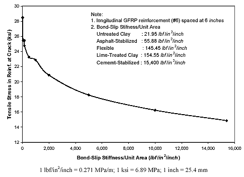
Figure 66. Graph. Tensile stress in GFRP reinforcement at crack versus bond-slip stiffness/unit area (ρ = 0.0074; granite aggregate concrete).
The performance of GFRP-CRCP in response to traffic loading is mainly dependent on the overall stiffness of the CRCP system. It is generally known that the flexural stiffness of the slab can be significantly influenced by the slab thickness rather than the reinforcement.(30) The thickness design, which determines the pavement stiffness, is accordingly dependent on load transfer coefficient, so it is currently thought that as long as the load transfer capability of GFRP-CRCP is satisfactory, the thickness of GFRP-CRCP may be able to remain the same, providing a pavement stiffness comparable to that of steel-CRCP.(2) Currently, the thickness design procedure of steel-CRCP follows that of conventional jointed pavement, and the thickness of steel-CRCP is also recommended to be the same as that of conventional jointed pavement.(2,10) However, it is still necessary to investigate the performance of GFRP-CRCP in the field to verify this preliminary concept of GFRP-CRCP thickness design. In addition, it is noted that CRCP8 was designed for steel-CRCP with empirical data collected from the field with only steel-reinforced CRCPs. Hence, the GFRP-CRCP performance predicted from CRCP8 needs to be verified by monitoring of future construction of a GFRP-reinforced CRCP in the field. It is noted that the current AASHTO limiting criterion of 1 mm crack width is developed from the steel-reinforced CRCP. Field investigation report(36) of steel-reinforced CRCPs shows that high load transfer efficiency (LTE) (about 90%) is maintained for CRCPs at different ages, and the LTE is not influenced by the amount of reinforcement used (0.5% to 0.75%) or the crack spacings (0.5 to 2.5 m). Further research is needed to investigate the relationship between the crack width and its corresponding LTE of a GFRP-reinforced CRCP.
A possible future construction of 27.94-cm- (11-inch-)thick GFRP-reinforced and steel-reinforced CRCP sections are being planned in Elkins, West Virginia, in 2005. Under a given construction condition from the West Virginia Department of Transportation (WVDOT), using number7 longitudinal GFRP rebars at 15.24-cm (6-inch) spacing on the line about 2.54 cm (1 inch) above the mid depth of the slab is predicted to be an economically applicable design for GFRP-CRCP with limestone concrete on the asphalt-stabilized subbase.In addition, number 6 GFRP rebars spaced at 1.219 m (48 inches (4 ft))will be installed as transverse reinforcement. For the steel-reinforced CRCP, number6 longitudinal steel rebars spaced at 15.24 cm (6 inches) will be adopted on the same subbase along with number5 transverse steel rebars spaced at 1.219 m (48 inches (4 ft)). After the construction, the field monitoring of both the CRCPs will be followed to compare and evaluate the performance of the GFRP-CRCP in terms of crack spacing, crack width, and the number of distresses (such as spalling and punchout).

