U.S. Department of Transportation
Federal Highway Administration
1200 New Jersey Avenue, SE
Washington, DC 20590
202-366-4000
Federal Highway Administration Research and Technology
Coordinating, Developing, and Delivering Highway Transportation Innovations
 |
| This report is an archived publication and may contain dated technical, contact, and link information |
|
Publication Number: FHWA-HRT-06-117 Date: December 2006 |
Previous | Table of Contents | Next
The NI-4552 Dynamic Signal Analyzer Board is used in conjunction with National Instruments VirtualBench DSA software to obtain time-domain data from ASTM C215 (impact method) testing of freeze-thaw test specimens and to convert that information to frequency response curves for use in determining resonant frequency.
The beams are placed on the piano wire. The accelerometer is fixed on the beam, and the hammer hits the specimen. The impact hammer and the accelerometer are connected to the BNC 2140 box. The data is processed.
Figure 39 shows the several plots generated after tapping a freeze-thaw beam with the impact hammer. There are four plots in the figure. The first plot (from top to bottom) shows the time domain waveform for the impulse (hammer). This is typically one “spike” at the time of impact. In some cases (as in a double hit), there will be more than one spike. The second plot shows the time domain waveform for the response of the beam (accelerometer). This plot is typically a damped vibration that decreases with time. The third and fourth plots show the frequency response of the beam due to the hammer tap. The third plot shows the frequency response over the baseband range (in this example, 0 to 3200 Hz). The frequency response on the fourth plot is over the zoomed range (in this case 1900 to 2300 Hz), and the resonant frequency can be manually obtained from it by placing the cursor on the peak of the curve. The frequency response curves should look similar to those shown in this figure. At lose observation, in plots 3 and 4 (especially plot 4), the frequency response curve for a good hit will be smooth as in plot 4. It will not be wavy, it will not have two or more peaks, and it should be roughly symmetrical. It should not have one or both ends cut off—the ends should appear to level off.
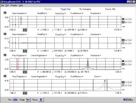
Figure 39. Screen capture. Typical plot generated by NI 4552 and BNC 5140 setup.

