U.S. Department of Transportation
Federal Highway Administration
1200 New Jersey Avenue, SE
Washington, DC 20590
202-366-4000
Federal Highway Administration Research and Technology
Coordinating, Developing, and Delivering Highway Transportation Innovations
 |
| This report is an archived publication and may contain dated technical, contact, and link information |
|
Publication Number: FHWA-RD-97-146 Date: NOVEMBER 1997 |
Previous | Table of Contents | Next
6.1 OVERVIEW
In hardened HCC, a void is an empty space, other than a crack, in the cement paste that contains nothing but air. The type, size, shape, arrangement, and abundance of the voids are factors controlling many important properties, such as compressive strength, resistance to destruction by freezing and thawing, and resistance to chemical attack on the reinforcing steel and the cement paste. The percentage of air void volume is generally specified by the design of the mixture. A large number of very small (most not visible without magnification) air voids are desired so that an appropriate amount of air can be distributed throughout the HCC in such a way that the distance between voids is very short and, thus, the paste is protected from freezing and thawing. A ratio of air-void volume to paste volume that exceeds the specified range weakens the HCC and may create channelways for the permeation and circulation of deleterious substances.
The total air-void content (of voids larger than capillary size) of an unhardened concrete mixture is routinely determined in accordance with ASTM C 231 (the pressure method) or ASTM C 173 (the volumetric method). Unit weight determinations (ASTM C 138) may also be determined to provide information concerning the percentage of air in the mixture. These methods do not ascertain the type of voids present; they merely measure the total void content. These measurements are important. As Bartel (1978) stated:
Tests for air content and unit weight of fresh concrete, carefully made in accordance with the appropriate ASTM test method, will yield an accurate measurement of the amount of air, weight, and volume of concrete being produced. Tests for air content, coupled with intelligently selected specification limits, can ensure the beneficial effects of entrained air in hardened concrete (p. 130).
Specially formed specimens of hardened HCC mixtures may be tested for resistance to the destructive forces of freezing and thawing in accordance with ASTM C 666 (resistance to rapid freezing and thawing). An HCC that is resistant generally indicates that an adequate air-void system is present or that the HCC has not become critically saturated.
It has been variously claimed that the total air-void content increases or decreases as the concrete hardens. It appears that what really happens is that the determination of total air-void content with field equipment made on the fresh concrete does not agree with the total air-void content determined by microscopical analysis of the hardened concrete. Except in the case of hydrogen gas being evolved by the incorporation of aluminum fragments (Newlon & Ozol, 1972) (see Fig. 6-1), no evidence of an equivalent change in the volume of concrete in the field placement or test cylinders has been offered as evidence corroborating the increase or decrease in total air-void content.
Careful investigation by a combination of controlled mixing and sampling procedures and petrographic techniques has shown that the air-void content does not change on hardening but rather may change due to outside influences, such as extreme overconsolidation (unusually long vibration, thus removal of more of the entrapped air than usual) or the further addition of water and retempering. The determination of the void
Figure 6-1 CONCRETE THAT INCREASED IN VOLUME DUE TO INCORPORATION OF ALUMINUM FRAGMENTS. Since it was cast in the cylinder mold, the concrete increased in volume due to the incorporation of aluminum fragments (from an aluminum delivery pipe). Thus, hydrogen gas evolved from the chemical reaction of the aluminum with the alkaline fluids of the fresh cement paste.
content in the hardened state should agree within 1 percent with the void content determined in the fresh, unhardened state. When they do not closely agree, either one of the measurements is in error or the two specimens tested do not represent the same concrete subjected to the same influences (see Appendix D and Ozyildirim, 1991).
An air-void content in excess of the amount required for protection against the destructive forces of alternate freezing and thawing that occurs in saturated concrete adds no benefit to concrete expected to bear loads and resist abrasion. (For a discussion of the high-air, cellular concretes, see Lesatski [1978] and Lewis [1978].) An excessive air-void content will lower the compressive strength of the concrete by about 5% for each excess percentage of voids.
In the early days of the use of air-entraining agents, there were some who saw that cracks ended at air voids and interpreted this to mean that the cracks started at air voids and were caused by them. In many parts of the United States, there was (and still is) a fear of an air-void content that exceeded the minimum specified. This may be interpreted as a fear of not meeting the compressive strength requirements. By nature of the bell-shaped probability curve, avoidance of high air-void contents can lead to air contents that are below the amount required for resistance to the destructive forces of freezing and thawing in saturated concrete. Conversely, there now seems to be, at least in this area of the United States among some concreting contractors, a fear of low air content. When HCC containing a percentage of air near the top limit of the specified amount is altered by the addition of retempering water (which can cause air-entraiing agents to be more active), an HCC with an air-void content considerably higher than the specified quantity is frequently produced: the result is concrete of insufficient strength (see Appendix D).
6.2 TYPES OF VOIDSThe overall void content in HCC is composed of four general types of voids, as listed in Table 6-1.
1. Capillary voids. Capillary voids are irregularly shaped and very small, less than 5 µm on the lapped surface of the slice examined. They represent space originally filled by mixing water, remain after the hydration of the cement gels, and are an integral part of the paste. Although they contain air at the time of examination, they are not considered part of the air void system.
2. Entrained air voids. Entrained air voids are defined at VTRC as spherical voids larger than the capillaries but less than 1 mm on the lapped surface of the slice examined. They are formed by the folding action of the concrete mixer, and their shape and size and abundance are influenced by the addition of surface-active air-entraining admixtures to the mixture.
3. Entrapped air voids. Entrapped air voids are voids that are larger than the entrained voids but have internal surfaces that indicate they were formed by air bubbles or pockets. They may be spherical or irregularly shaped.
4. Water voids. Water voids are irregularly shaped voids whose shape, location, or internal surface indicates that they were formed by water. Usually, they are larger than entrained air voids.
6.2.1 Capillary Voids
The smallest class of optically visible voids in HCC are the various sizes of capillaries. A very few of the larger capillary voids may be seen at the higher magnifications used to determine the parameters of the void system, but they are generally not that large. Capillary voids are spaces formed by the shape of the hydrated cement gel structures and spaces left between the gel structures as water is used in the self-desiccation of the hydration process. They were occupied by water or gas when the concrete was fresh and are larger and more abundant in concretes with a high water-cement ratio. The magnitude of the capillary system is controlled by the water-cement ratio and the degree of maturity of the concrete. The evenness of the distribution of the pores and capillaries is controlled by the distribution of the water. As the concrete hydrates, the water in the pores is used in the hydration of the cement. As the concrete matures, much of the capillary space becomes filled with the products of hydration and the products of any reactions occurring between the chemicals of the paste and the aggregate rocks. Some of the finer capillaries are spaces created by differential crystal growth. (See Chapter 13 and associated figures and note how the quality of the fine aggregate affects the distribution of moisture and thus pores and capillaries in the paste.)
The capillaries are detected only when specialized methods are used. In laboratories so equipped, the various types of electron microscopes may be used to view the capillary void system. In the VTRC laboratory, the abundance and location of the capillary voids are detected by use of the P/EF microscope in the study of fluorescent thin sections of the specimen concrete (see Chapter 13). Rarely, capillary voids may be noted during the determination of the parameters of the void system. In that event, capillary voids are considered to be paste.
6.2.2 Entrained Air VoidsEntrained voids are small spherical voids enfolded by the mixer. Surface-active, air-entraining agents are added to the mixture to stabilize a specified percentage of these voids and thus protect the hardened HCC against the destructive forces of freezing and thawing. Thus, the entrained air void is a desirable void. Entrained air voids are generally considered to be larger than the capillaries (at least 5 µm in diameter) but smaller than the voids considered to be entrapped voids (Verbeck, 1966, 1978). Entrained air voids have so much surface tension relative to their volume that they are distorted very little by the shape of nearby particles. Distortion occurs in these small voids only when external forces distort the concrete after the beginning of hardening.
The presence of the proper quantity of well-distributed entrained air voids can prevent deterioration of the concrete (even when saturated) by the mechanisms of freezing and thawing (Helms, 1978; Newlon, 1978) and facilitate the placement of the concrete because the entrained air voids act as additional fluid, almost as though the entrained voids were ball bearings. In Virginia, the proper quantity of air voids is defined for each class of HCC by Road and Bridge Specifications (1991). Entrained air voids allow the relief of pressures caused by the freezing and thawing of saturated HCC and thus protect the HCC from destruction by these mechanisms. The exact method by which they perform this function has not been determined and agreed on by all concrete technologists, but all agree that the empirical evidence demonstrates that the presence of a sufficient quantity of sufficiently small (entrained size), properly distributed air voids protects the cement paste in the concrete from deterioration by freezing and thawing.
Very irregularly shaped small voids (maximum dimension less than 1 mm) cannot be properly called entrained voids because the surface tension caused by the air entraining agent is lacking. It is not known if such voids function to protect the concrete against the deterioration caused by freezing and thawing. Small, irregular voids, particularly if not at an aggregate boundary or a wearing surface, may be evidence of retempering (see Appendix D).
Figures 6-2 and 6-3 show varying percentages of air voids.
6.2.3 Entrapped Voids and Water Voids
All voids, regardless of shape, that have a maximum dimension (on the surface examined) of more than 1 mm are defined at VTRC as entrapped voids (large spherical) or water voids (large irregular). If voids occur flattened out at the boundary between the aggregate (usually coarse aggregate) and the paste, they are a class of entrapped voids called boundary voids.
All voids larger than entrained voids have no appreciable beneficial effects and weaken the HCC. Such voids are partially controlled by the efficiency of whatever system of consolidation is in use. Certain voids may be caused by too much water in the HCC, a strong affinity of a particular aggregate lithology for water, improper consolidation, and occasionally by the dissolving away of Ca(OH)2. Irregularly shaped voids, regardless of size, may be caused by water pockets or air pockets that
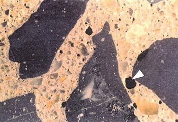
Figure 6-2 SURFACE OF FINELY LAPPED SLICE OF CONCRETE CONTAINING 5.6% TOTAL AIR VOIDS. The void content of this concrete is in the middle of the specification range. The large void marked with an arrow is about 2 mm across (larger than an entrained air void). Notice the very fine voids throughout the paste.
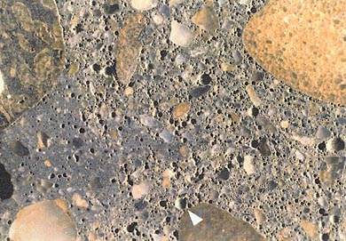
Figure 6-3 SURFACE OF FINELY LAPPED SLICE OF CONCRETE CONTAINING 17% TOTAL AIR VOIDS. The void content of this concrete is way above the upper limit of the specification range. The void indicated by the arrow is about 1 mm across. The area of darker paste (lower left) has a lower void content. An HCC that contains more than one kind of paste generally indicates that the mixture had begun to hydrate before additional water was added (see 8.4 and Appendix D).
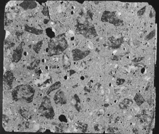
Figure 6-4 CONCRETE CORE WITH ABOUT 4% LARGE IRREGULAR VOIDS. In this instance, the concrete, which had not yet been consolidated, became hard and unworkable while repairs were being made on the paving equipment.
the consolidation procedures did not remove (see Fig. 6-4). Water voids are irregularly shaped voids created in the HCC by bleed water prevented from rising to the surface by an aggregate particle or the hardening of the paste. Water voids contained water when the HCC was fresh and unhardened. In the hardened state, these voids are filled with air and might be more properly termed water-formed air voids.
6.3 QUANTITATIVE DETERMINATION OF AIR-VOID PARAMETERS
In hardened concrete, the parameters of the air-void system may be determined by obtaining the data and performing the calculations specified in ASTM C 457. The parameters calculated include:
1. Air-void content (symbolized in ASTM C 457 by A). It is a percentage by volume. A minimum amount of air voids are required to protect the concrete from the expansion of water during freezing. Excess air-void content will cause the concrete to have less than the intended compressive strength.
2. Void frequency (symbolized in ASTM C 457 by n.) It is the number of voids per unit length of traverse. The void frequency is required in the calculation of the average chord in the modified point-count method.
3. Average chord length (symbolized in ASTM C 457 by T). It is the length of the sum of the chords of the air voids divided by the number of voids encountered in the traverse.
4. Specific surface (symbolized in ASTM C 457 by a). It is the surface area of the average void divided by the volume of the average void. It is calculated from the average chord. The unit involved can be expressed as squared units divided by cubed units or as units to the minus 1 power. The higher values (higher void surface area per void internal volume) indicate smaller voids. Small voids (with shorter average chord) are desired because they disperse throughout the concrete with small unprotected volumes of paste in between. If the same air-void content was present in larger voids, the unprotected volumes of paste would be much larger.
5. Spacing factor (symbolized in ASTM C 457 by L). It is calculated from the specific surface, the percentage of air voids, and the percentage of paste (see 7.1) that must be protected. It is expressed as a decimal value of the measurement unit. The spacing factor is a theoretical measure of the average distance water, ice, or expansive force must to travel in HCC before it contacts an air void, i.e., half the average distance between air voids. The smaller the spacing factor, the more completely the air-void system can protect the concrete against deterioration by freezing and thawing. Regardless of the ratio of air-void volume to paste volume, the higher values for void frequency and the concomitant shorter average chord length result in smaller spacing factors and a more desirable air-void system.
New methods and equipment are continually being devised to monitor and determine the air-void parameters of hardened concrete. It is part of the job of the petrographer to assess the value of new methods and equipment and decide which method is of value in which situation and, therefore, which equipment is worthy of a place in the budget of the organization. If the results of an air-void determination are to be presented in court and the testimony of opposing expert witnesses will be heard, any deviation from the principles of ASTM C 457 that has not been agreed on by the client may invalidate the results of the analysis. Within an organization, certain deviations from the strict interpretation of ASTM C 457 may be acceptable.
According to ASTM C 457, air-void system analyses can be efficiently performed with several methods and kinds of equipment. Suitable equipment for the determination of air-void parameters in hardened concrete includes, but is not necessarily limited to, (1) linear traverse, (2) modified point-count, and (3) image analysis equipment. In common, the types of equipment to be used permit or facilitate the movement of the specimen of HCC on the stage of a microscope so that data may be collected over the specified area and from the specified length of traverse. In common, the data collected are:
1. The total length of traverse over which the determination is made. In the modified point-count method, the total number of points examined and the distance the equipment moves between the points are required for the calculations.
2. The portion of the traverse that is across air voids. In the linear traverse method, this portion is the sum of the chord lengths across air voids; in the modified point-count method, this portion is the number of points that occur in air voids multiplied by the distance the equipment moves between points.
3. The number of voids occurring in the traverse examined. The accuracy of the determination of the specific surface and spacing factor is completely dependent on the accuracy of the count of the number of voids on the line traversed. In the linear traverse method, the number of voids in the traverse is the number of chords collected; in the modified point-count method, it is the number of voids counted along the traverse line.
The procedures detailed in ASTM C 457 are those to be used with nonelectronic types of equipment (see ASTM C 457, Figs. 2 and 5). When equipment is used that includes automatic devices for moving the specimen, electric or electronic counters or totalizers and calculators, or measuring devices, the equipment must allow adherence to the principles of ASTM C 457 and permit or perform the calculation of the same parameters of the air-void system from the same data. The exact procedures followed for the operation of the equipment must be those described and specified by the fabricator of the equipment.
It is not known which type of equipment produces the most accurate results or how accurate the results need to be. Point count is favored by those who need speed. Linear traverse is favored by those who wish a record of the chord length distribution for research purposes. Image analysis is favored by those who desire speed and the ability to collect a lot of data and manipulate it on a computer in many different ways. Image analysis can strain the equipment budget but requires less operator time since the specimen is not examined by the human eye. Image analysis equipment is not available at VTRC. Research laboratories will usually require either point-count or image analysis equipment for speed in making routine determinations and linear traverse equipment for its ability to determine chord length distribution on a surface unaltered by the fillers and dyes required by image analysis.
| >NOTE: The air-paste ratio method of calculation detailed in ASTM C 457 is to be used ONLY (1) when proportions of the ingredients in the mixture are known with some certainty, (2) it can be assumed that no change in mixture proportions has occurred (e.g., retempering has not occurred; i.e., the amount of paste can be closely calculated), AND (3) because of the lack of exposure of a generalized specimen of the HCC or because of the extremely large size of the aggregate it is impossible to obtain a specimen of the HCC for microscopical analysis with an aggregate distribution that is representative of the placement. The air-paste ratio calculations use the aggregate-paste ratio of the design of the mixture to transform mathematically the air-paste ratio determined microscopically to percentage air voids, specific surface, and spacing factor. In these situations, it is convenient to select a specimen of HCC that is low in aggregate so that the microscopist will not have to spend excess time moving over aggregate. |
Using the linear traverse equipment (see Fig. 6-5), the operator tabulates the chord lengths across all phases of interest and records them for later analysis (Walker, 1988). This sort of data permits the straightforward calculation of the void parameters by the summing of the lengths of the chords and counting of each occurrence of
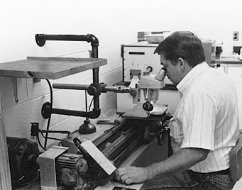
Figure 6-5 PARTIALLY AUTOMATED LINEAR TRAVERSE EQUIPMENT FOR DETERMINING AIR-VOID PARAMETERS
a phase. Because the calculations are extremely sensitive to errors made in the determination of the number of voids traversed, the method of deciding whether a void is or is not touched or transected by the line of traverse must be carefully employed in any case of doubt. If the individual lengths of the chords of the air voids are recorded and certain shape assumptions are made, a graphical representation of the chord lengths will indicate the size distribution of the air voids. The collection of the air-void data requires one pass of the microscope along the traverse line. The data necessary for calculation of the paste content may be collected at the same time or a separate determination can be made for the paste content. This procedure is further discussed in 7.1.2. With some types of linear traverse equipment, all the air-void parameters are automatically calculated; with others, the calculations must be performed on a calculator or computer.
With the point-count equipment (see Fig. 6-6), the operator records the type of substance (air void, paste, or aggregate) appearing at the index point of the reticle at a large number of points as provided by a click stop on the stage. The points may be randomly distributed or regularly distributed on a randomly placed grid or a traverse line. Data concerning the relative amounts of all the phases can be collected from one pass along the traverse line. Calculation of voids per unit length, average chord length, specific surface, and spacing factor usually requires that a second pass along the traverse be used to count the number of voids occurring on the traverse line. Although the majority of users of the point-count apparatus collect the information concerning the abundance of paste during the same pass on which that concerning the abundance of air is collected, they may sometimes find difficulty in
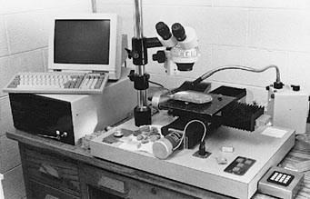
Figure 6-6 FULLY AUTOMATED EQUIPMENT FOR DETERMINING AIR-VOID PARAMETERS. Either linear traverse or point-count software can be used to control the computer and the motion of the stage.
distinguishing the exact paste-aggregate boundary and might wish to consider a separate pass over a lightly etched surface to collect these data (see 7.1.2). The air-void parameters may be calculated by the analysis equipment or separately calculated using a calculator or computer.
Image analysis equipment (see Fig. 6-7) requires that the specimen be specially prepared so that each of the three major phases of interest (voids, paste, and aggregate) is a distinct tone (e.g., white, black, and medium gray). The presence and shape of areas of the three selected tones are determined by electronic eye, and the data are automatically recorded, sorted, and calculated. The specimen preparation methods for image analysis can be exacting and make the surface used useless for ordinary stereomicroscopic examination (as described in Chapter 8). If it is desirable to examine the distribution of phases with the human eye later, when the specimen is sawed, the surface facing the surface that is to be colored and filled should be finely lapped for microscopical evaluation. Both of these surfaces should be kept intact and safe until all controversy regarding the concrete is over. Automatic systems that require filling the voids (thus hiding their interior surface) cannot be used to make certain distinctions possible by a human operator. The human operator can often mentally reconstruct what the surface examined would have been if this or that flaw had not occurred. The human operator can judge if a void observed is an air void, a fly-ash cenosphere, or the hole left where a small round grain of sand has fallen out. These distinctions are generally possible by study of the reaction products and the luster of the interior of the void.
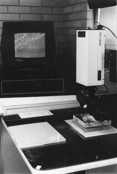
Figure 6-7 IMAGE ANALYSIS EQUIPMENT. The instrument is shown in the process of analyzing the air-void system of a slice of concrete. The screen in the background shows the progress of the analysis. (Photograph by R. H. Howe, courtesy of PennDot.)
At VTRC, it has long been recognized that the accuracy of a linear traverse determination of the air-void parameters is as dependent or more dependent on the number of voids encountered and measured along the traverse as it is on the length of the traverse. Once 1,000 voids have been measured and counted, the results from the data obtained subsequently change very little. Snyder, Hover, and Natesaiyer (1991) made an analytical investigation of the effect of the number of voids and the length of the traverse on the minimum expected error that can be encountered in a linear traverse determination of the void parameters in hardened HCC. Their work supports our belief that little additional accuracy is achieved if the determination includes more than 1,000 voids and that almost no additional accuracy is achieved with more than 2,000 voids.
For intradepartmental purposes, for ordinary determination of the air-void parameters, it has been our practice to estimate visually the number of voids per unit length of traverse, consider how long a traverse is required in order to obtain data on 1,000 voids, and then plan how to spread the traverse length evenly over the specimen surface available. Under circumstances when ASTM C 457 requires 100 in. of traverse, we estimate that only 50 to 70 in. is required for the collection of data from 1,000 voids in ordinary within-specification concrete. Should some legal controversy arise concerning the subject concrete, any traverse length deficiency can be made up by collection of data from the lacking inches of traverse (also evenly distributed over the surface). If the traverse direction and starting point are randomly chosen, in both cases, the randomness of the data collection will be maintained. It is our view that spreading the data collection area over as large a surface area as possible so that any irregularities of void distribution (any clumping or areas devoid of voids) become part of the data recorded and examined is more important than the length of the traverse line.
The corollary is that if the number of voids is very small due to low air content or large voids, the length of traverse recommended in ASTM C 457 is probably not sufficient to obtain accurate air-void parameter data (Snyder, Hover, & Natesaiyer, 1991). Under such circumstances and with borderline compliance with specifications, it may be wise to use an additional length of traverse to ensure accuracy In most cases, the small specific surface and large spacing factors caused by the lack of sufficient small voids will decisively indicate lack of compliance with the specifications.
The method of deciding whether a void is or is not touched or transected by the line of traverse must be a simple rule that is firmly adhered to throughout any particular analysis. Pleau, Plante, Gagne, and Pigeon (1990), using the point-count method, recommended: "A simple way to guarantee a random choice is to systematically choose the constituent located in a given quadrant (of the field viewed), say the upper left corner of the cross-hairs." A similar method can be devised for whatever type reference point, reticle, and counting method are in use. Other researchers (Mather for one [1989]) have suggested that points in dispute be collected in a separate register and later distributed to the totals of the constituents in the same proportion as are the data concerning which there is no dispute.
6.3.3 Preparation of Specimens
The importance of the proper preparation of the surface of the slice of concrete cannot be overemphasized (see Figs. 5-2 and 5-3). In most laboratories, specimens are prepared by skilled, highly trained technicians. A poorly prepared specimen can cause a determination of the percentage of air present in a specimen to deviate from the true value by as much as 2 percentage points (20% to 50% of the true value). A rough surface makes it impossible to detect small voids. This will have the effect of lowering the detected percentage of air, decidedly lowering the specific surface, and. thus raising the spacing factor. Quantitative determination on a surface that is undercut and wherein the edges of the voids have been chipped or worn away can provide data that indicate the presence of more air than really exists.
The preparation methods used by Pleau et al. (1990) can be questioned. They advocate soaking the slices (slabs) in water for a few days, presumably to complete the hydration and produce a more stable material for lapping. (Chapter 5 has several suggestions for the treatment of weak or immature concrete before lapping.) However, water can wash away reaction products, liquefy expansive alkali-silica gels, dissolve calcium hydroxide crystals, loosen aggregates in their sockets, change the appearance of the inner void surfaces, and weaken thin paste walls between voids. The void walls and remnants of void walls serve to define the void boundaries and facilitate the recognition of the individual void structures. If the inner void surfaces are in their original condition, the luster, surface texture, and asperities on these surfaces can help distinguish the differences among entrained voids, entrapped voids, water channelways, and aggregate sockets. Thus, water should not be used in sample preparation. It is common practice in concrete laboratories to use a saturated solution of calcium hydroxide as the water bath whenever specimens of concrete are soaked in water (for testing absorption etc.) to prevent weakening the concrete by dissolving of the contained calcium hydroxide that is an important part of the structure of most concretes. The calcium hydroxide solution may have undesirable effects on specimens prepared for microscopical analyses and is not recommended for this purpose.
Each method of producing a finely lapped specimen surface for microscopical study will probably produce different effects on different types of concrete (different water-cement ratios, different kinds of aggregates, different degrees of maturity and deterioration).
In certain concretes in which the shape of the air voids has become distorted (see Appendix D), all manner of overlaps and crushing of voids may occur; the operator should be alert and ready to record the data for each void in a logical and consistent manner.
6.3.4 Technician Considerations
The linear traverse and modified point-count methods are tedious and hard on the eyes. A single determination of the air-void parameters of a concrete by means of the linear traverse method can take up to 7 hr, depending on the size and quantity of the voids. A technician cannot spend more than 4 hr a day doing this sort of work on a day-to-day basis. Everyone who has tried has found that the ability of their eyes to focus has deteriorated on the following day. The training and keeping of good microscopical technicians can be a major undertaking requiring tact, skill, understanding, and a flexible schedule of rest periods.
Image analysis systems do not require that the operator be with the equipment after the initial adjustment; thus, eye fatigue and the need to train technicians to perform microscopical analyses are eliminated.
The following points are important considerations in the hiring and training of technicians for the microscopical analysis of air-void systems:
Try to avoid hiring operators for linear traverse and point-count determinations of air-void parameters who do not have good binocular vision.
Keep available standard specimens of concrete with a range of different types of air-void systems. Air-void contents of 2% to 14% are recommended. These should be specimens that have been analyzed by a number of different operators. The results previously obtained should be kept in a secure place by the supervisor. Each new operator who is trained for this work should be tested on the standard specimens, and training should continue until the results of the new operator are comparable to the range of results recorded in the past.
Make sure that each operator knows how to adjust the positioning of the specimen so that it is flat and so that the specimen can move under the microscope and remain in the same focal plane. This procedure can be a tedious nuisance and may be neglected if its importance is not sufficiently emphasized during the training of the operators.
Make sure that each operator knows how to adjust the binocular vision spacing; the height of his or her chair; and any other items available for greatest visual acuity, comfort, and convenience. The operator must understand that these adjustments are not emphasized for his or her personal comfort but rather because proper adjustment adds to the accuracy of the determination. An operator suffering from a headache or backache is not as able to produce good data as a comfortable, healthy operator.
Make sure that the operators understand the need for good focus and how to achieve good focus on the reticle for their main eye and simultaneous good focus on the specimen for both eyes. Each person has one eye that looks straight ahead (the main eye). The other eye observes things at an angle. Whenever an optical technique requires a reticle in one eyepiece of a binocular system, the retide should be placed in the lens system used by the main eye.
If the microscope is used by more than one person, make it a routine practice for each operator when beginning work to check the focus of the reticle and the focus of the surface being examined. Emphasize that the surface should be in focus throughout an entire traverse across the specimen. If focus is lost, errors will be great and the ability to judge the type and origin of a flaw in the finish of the surface being examined will be seriously diminished.
Observe the actions of the operators and determine if they are following instructions. From time to time, have the work of the operators checked by having another operator redo a specimen, an operator redo a specimen done some months ago, or an operator redo one or more of the standard training specimens.
Teach operators that great care must be taken to include in the count every void crossed by the traverse. The air-void count should be performed slowly and accurately. Very small voids and voids that are just barely touched by the traverse line must be counted. When the linear traverse procedure is used, it may be necessary to slow the motion along the traverse almost to a stop (if not completely) to register very small voids in the count. If it is realized that a void with an essentially zero chord length (because the traverse line is tangent to the void or because the void is very tiny) has not been counted, it is possible with some equipment to bring the motion along the traverse to a halt (so that zero chord length is recorded) and press momentarily the button that registers the presence of the appropriate void type. The location of a void along the traverse line is not a matter of concern, and the operator can record it anywhere. In the modified point-count method, no automatic motion is usually used while air voids existing along the traverse line are counted; therefore, this error will not be made in the same way.
Determination of the abundance of the various types of voids is very useful in concrete research. It can make data available that can change various practices in the mixing and placing of HCC. As an example, it was once thought that the speed of the screed pulling the vibrators through freshly placed concrete did not affect the degree of consolidation. This did not seem logical to some. The Ballenger Construction Co. of North Carolina set up a series of test sections of pavement in which the speed of the screed was carefully controlled. A detailed petrographic laboratory analysis of the abundance of the various sizes of voids in the air-void system of 24 cores that had been removed from these test sections showed that there is a good inverse relationship between the speed of the screed and the degree of consolidation (Walker, 1972a). As a result, the maximum speed of the screed is now limited in many specifications.
The quantitative determination of the abundance of various types of voids can be an important part of the petrographic analysis of a specimen. In the normal usage of linear traverse equipment in the VTRC petrographic laboratory, the abundance of each of the three types of air voids (entrained, entrapped, and water formed) is routinely determined (see Table 6-1). With equipment designed for this purpose, this determination may be performed concurrently with the determination of the other parameters of the air-void system.
In a finely lapped slab or a thin section, the size and shape of voids can be used as indicators of void origin and type. The luster and texture of the interior of the voids may sometimes be used in the recognition of voids caused by accumulations of water and passageways for water. The properties on which distinctions may be made between the various types of voids are arbitrary and may vary from one laboratory to the next. Because these distinctions are made on the appearance of a void on the surface of a slice (where the third dimension of the void cannot be seen), many large voids will be classified as entrained voids when they are really entrapped voids. As indicated in Figure 6-8, a small section through a large void can, in two dimensions, be indistinguishable from a large section through a small void. A cross section that is larger than the defined maximum for entrained voids must be a section of an entrapped air void or a water-formed void. A large number of large cross sections indicates a large number of large voids.
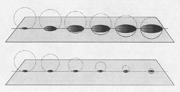
Figure 6-8 ILLUSTRATION OF VARIOUS SIZES OF SECTIONS THAT MAY BE EXPRESSED ON RANDOMLY PLACED PLANE
6.4.2 Distinguishing Between Entrapped Voids Caused by Air and Those Caused by Water
The petrographer can often distinguish between entrapped voids caused by water pockets and entrapped voids caused by air pockets. The estimate will necessitate careful observation and some extrapolation. In general, the interior surface of an air void will appear smoother, sometimes even shiny. A water void will usually have a dull interior that appears to have had small particles and precipitates deposited on it. In the case of water-formed voids, the shapes of the bounding aggregate particles are often visible in the interior of the void. Water voids may have an interior showing water movement patterns, may be interconnected bleed water voids, or may show by nature of the internal deposits and asperities and by position that they are water pockets trapped by aggregate particles.
6.4.3 Determination of Size Break Point Between Entrained and Entrapped Voids
The determination of the size break point between entrained and entrapped voids varies from laboratory to laboratory and must be interpreted in light of the method of measurement. For example, if the voids whose maximum chord on the surface examined is less than 1 mm are defined as entrained voids, then some voids whose true diameter is larger but not observable because the diameter is not in the plane of observation will be classified as entrained voids. The petrographer should maintain a clear idea of the meaning of the methods of determination in the size sorting of the voids.
A random line of traverse through HCC has a greater chance of traversing a large void than a small one. The probability ratio is as the ratio of their volumes (see Fig. 6-9). The calculations detailed in ASTM C 457 are designed to be used on the sums of the chord lengths and on the count of the voids regardless of the desirability or relative amounts of the various sizes. If the large voids are not counted and measured as part of the overall determination of the void system (suggested by Sommer [1979]), the control against large voids provided by the determination of the specific surface and spacing factor will have been blocked and the apparent precision of the method spuriously improved (Walker, 1980).
Unless the method and the criteria used to obtain data concerning void size are rooted in statistics, the data are only rules of thumb and valid only when compared with data obtained by the same methods. Calculations can be made on the distribution of the void sizes from chord data if certain assumptions are made concerning shape, heterogeneity, and isometric distribution of air voids.
At VTRC, the diameter of the section of the void as seen on the finely lapped surface examined must be equal to or less than 1 mm for the void to be considered an entrained void. In other laboratories, the length of the chord on the traverse line across the void is the parameter measured. The latter method makes it possible to set up an automatic electronic classification and counting system for entrained versus entrapped voids. In some European laboratories, the chord must be 0.3 mm or less for the void to be considered an entrained void (Wilk, Dobrolubov, Romer, 1974). A void viewed in a lapped surface may be transected by the surface either above or below its true diameter, and there is no known way to measure an actual internal diameter. Efforts have been made to peer into a void to try to get an estimate of the true diameter, but in my view these efforts serve only to confuse the issue.
 |
 |
Figure 6-9 TWO EQUALLY SPACED ARRAYS OF VOIDS. Each is crossed by a randomly oriented plane. There is the same number of voids in a unit area in each array. Note that the plane touches more voids (see arrows) when the voids are large than when the voids are small.
In many laboratories, decisions on individual void size are made on the lapped surface as viewed. A large void, more than 1 mm in diameter, may be so oriented that the surface examined truncates only a small portion of the void, the extreme top or bottom, when considered from the finely lapped surface. Thus, there will always exist a larger proportion of large voids than can be recognized on the surface examined (see Fig. 6-8).
The procedures given here are for the linear traverse method when the chord lengths are collected by an operator depressing an electric recording device and either a paper printout is produced or three collecting devices are available (Walker, 1988). The point-count method does not survey every void on the traverse during the percentage portion of the examination and, therefore, does not allow a classification of every void. Image analysis procedures are not discussed in detail because such equipment is not available at VTRC.
1. Examine each void when the void's leading edge comes to the index point (usually the center of the cross hairs), and determine which type of void is present. With the wide-angle lenses and a magnification of 100X or less, voids of less than 1 mm in diameter will be completely visible in the field of view. Most voids can be classified at a glance as either entrained, entrapped, or water formed. When borderline cases occur, use a finely marked metric ruler on the slice, in the field of the microscope, to determine void size (at low magnification, an eye- piece micrometer may be used).
2. Record the presence of the void and the length of the chord across it in the usual manner for linear traverse (by pushing down a button and holding it down until the trailing edge of the void is at the index point). If three buttons are available for the three types of voids, each with their own totalizing devices that separately measure, total, and count the voids, depress the button appropriate for the type of void determined in step 1. If the chord lengths are recorded by using only one button and are individually printed on paper and the void encountered is not an entrained void, stop the motion of the traverse stage and mark the paper tape at the chord measurement with a symbol to indicate the classification of the void measured. Continue with the analysis; repeat from step 1 for each void.
3. When the analysis is complete, add the lengths of the chords for each type of void (if not added by the linear traverse device employed) and report the percentage by volume and the count (individual voids per specified inches of traverse) of each in the total concrete.
6.5 MEANING OF AIR-VOID PARAMETERS
The major parameters of the air-void system are interdependent. Some specifiers of concrete will require only that the air-void content is within certain limits; others will require that the spacing factor be below a certain limit or the specific surface be above a certain limit. Because one-sided limits on spacing factor and specific surface do not indicate the presence of a too high air-void content, the air-void content should be required to be within an upper as well as a lower limit.
The following are some of the issues the air-void parameters will determine:
Resistance to deterioration caused by freezing and thawing. When ASTM C 457 is followed with care and the report is as instructed therein, the numerical data obtained will clearly indicate the ability of the cement paste in the concrete represented by the specimen to resist the destructive forces of freezing and thawing. A specific surface of more than 600 in.-1 (in.2/in.3) and a spacing factor of less than 0.008 in. indicate an HCC with a paste having an air-void system of the type that will resist severe winter weather conditions in a mature HCC containing few microcracks. Certain concretes with a very low permeability (and usually a very high strength) may resist the forces of freezing and thawing without meeting these requirements either because they never get critically saturated or (less likely) they lack sufficient freezable water when saturated.
Use of specific admixtures. The petrographer is often asked if certain admixures or an excess amount of a certain admixture has been used in a specific concrete. Extraordinarily low spacing factors accompanied by a high specific surface can indicate either excessive air-entraining agent or (if the total air content is within specifications) the use of a highly specialized admixture. During the first trials of some of the high-range water reducers, the paste was exceedingly compact but many of the voids were large. This created a specific texture, as illustrated in Figure 6-10. The high-range water reducers used in present-day mixtures do not create such a high content of large voids, but some concrete with this texture is still in service and requests to examine these concretes can still come in.
Flaws. An unusually large number of voids that appear to have held water when the concrete was fresh indicate flaws in either the proportioning or the workmanship. An abundance of entrapped voids indicates either poor consolidation or early loss of slump.
Figure 6-10 TYPE OF VOIDS AND PASTE TEXTURE PRODUCED BY EARLY TYPES OF HIGH-RANGE WATER REDUCERS. Such large voids do not add to the resistance of the concrete to freezing and thawing but do lower the compressive strength. The scale is in millimeters.
The data concerning the distribution of the types of voids as detailed in 6.4 can be used to discover certain placement conditions, such as the efficiency of the consolidation and reasons for various nonstandard conditions (such as low compressive strength or high permeability). Sometimes, when hand-held vibrators are used, there is excess entrapped air because of the persistent but erroneous belief that the specified amount of vibration will cause a loss of a portion of the required entrained air. It has been demonstrated that vibration even 2 or 3 times as long as the required amount does not reduce the entrained air in properly proportioned mixtures (R. H. Howe, personal communication, October 24, 1991). Although the maximum allowable quantity of large voids and the mathematical expression of a large quantity of large voids in a high spacing factor and low specific surface are not parameters required by the specifications of VDOT (thus difficult to argue in a court of law), it is important to consider these parameters and be able to explain their meaning. In general, it is much easier to talk about a large quantity of large voids than to explain the mathematical derivation of the specific surface and the spacing factor. If the percentage of the large voids exceeds 1.5%, it is considered high. More than 2% is considered excessive, and explanations for the prevalence of the large voids is sought. Does the concrete appear to have been retempered? Improperly mixed or consolidated? What is the reason?

