U.S. Department of Transportation
Federal Highway Administration
1200 New Jersey Avenue, SE
Washington, DC 20590
202-366-4000
Federal Highway Administration Research and Technology
Coordinating, Developing, and Delivering Highway Transportation Innovations
 |
| This report is an archived publication and may contain dated technical, contact, and link information |
|
Publication Number: FHWA-RD-97-146 Date: NOVEMBER 1997 |
Previous | Table of Contents | Next
8.1 OVERVIEW
The stereomicroscopic examination of lapped surfaces of the specimen is usually The procedure that controls the course of the analysis of the specimen. If the Specimen was submitted for a specific analysis and the petrographer is fairly sure that the other parameters of the concrete do not require investigation (as may be the case when the concrete has been fabricated in a concrete laboratory), the stereomicroscopic examination of the concrete may be omitted. Usually, the petrographer cannot be sure that the examination requested will provide sufficient information to discern all of the possible problems of the concrete submitted and will perform a general stereomicroscopic examination to allow analysis of all the features of the specimen.
The concerns of the client must be considered throughout any examination of the specimen. However, the observations made should not be confined to these concerns: all the features of the entire suite of specimens should be inspected and examined in detail. Often, the petrographer is asked to confirm or deny the sence of a certain form of distress but then finds that there are other kinds of problems sent as well.
After any planned quantitative analysis of the constituents (see Chapters 6 and 7), five procedures are performed in a general examination with the stereomicroscope, as listed in Table 8-1.
Table 8-1 PROCEDURE-EXAMINATION WITH STEREOMICROSCOPE
1. Review the data.
2. Prepare the equipment.
3. Examine the slice, and mark and label it appropriately.
4. Enhance the marked features.
5. Photograph the slice, and make photomicrographs.
8.2 REVIEW OF DATA
In the normal course of events, the preliminary examination (described in Chapter 3) is performed and then the specimen is prepared according to the preliminary plan of analysis. If the plan of analysis includes the determination of the air-void parameters, the procedure is usually performed by a technician. Thus, several days may have elapsed between the original preliminary examination by a petrographer and the stereomicroscopic examination. Occasionally, the plan of analysis may have been sketched out by a different petrographer than the one performing the stereomicroscopic examination. If the petrographer's workload is heavy, the time when it is convenient to perform the stereomicroscopic analysis of the specimens may be a few weeks after the receipt of the specimen. Therefore, it is usually necessary that the petrographer review the complete history of the HCC and be aware of anything unusual about the design of the mixture and any unusual procedures or occurrences during placement. With this information, the microscopist will be best able to notice and report on any features that might be attributable to new methods, materials, or admixtures or that might have been caused by the incidents that occurred during the placement of the HCC. Therefore, the petrographer should review the following: (1) the history of the concrete being studied as reported by the client either in accompanying documents or orally, (2) any unusual methods of sample preparation that were required, (3) any features noted by the technician during the preparation of the specimens and the air-void analysis, and (4) the results of the air-void analysis.
The stereomicroscope (see Fig. 2-17) should be placed on a table or stand that is a convenient height for the microscopist. A variety of microtools (see Fig. 2-18), bottles, and droppers to supply water and 10% HCl and a variety of marking equipment to make both temporary and permanent marks on the surface of the lapped slice should be available. A variety of pens; soft, colored pencils; and sticky paper arrows, dots, or other labels for use on the surface of the lapped slice should also be available.
Various pens should be tested on some fine microcracking on an unimportant lapped, oil-free slice of HCC. No particular brand of pen is recommended because inks and pens change as manufacturers find new ways to please the public or economize their operations. The soft or fiber-point disposable pens that have a medium-thick fluid ink work well. While using the stereomicroscope, the microscopist positions the pen on a microcrack and causes a very small portion of the ink to flow on the visible expression of a crack. If the ink enters the crack (as opposed to beading up on the surface) and by capillary action is drawn a short distance along the crack (without bleeding into the mass of the paste), this small leading portion of the ink, visible with the stereomicroscope, indicates the next direction of the crack. By the use of the proper pen to trace the direction of the crack with ink, it is possible to detect and mark microcracks and connections between cracks that cannot be seen against the general paste background at the magnifications of the stereomicroscope. If such pens are available in several colors that will contrast with the HCC, various features can be marked with different colors.
Other pens and pencils are for marking on aggregate surfaces. Light pencil marks are not easily seen on the lapped surface of paste, and heavy pencil marks may damage the surface or fill cavities with graphite or colored flakes.
8.4 EXAMINATION AND MARKING OF SLICES
Table 8-2 is a checklist of the features that should be examined. The following procedure should be used:
1. When there is any possibility of the labeling obscuring your ability to see details in the paste (usually the case when using ink to emphasize microcracks), delay any permanent marking and labeling on the paste until you examine the slice for all the other items on the checklist. When
Table 8-2
CHECKLIST FOR EXAMINATION WITH THE STEREOMICROSCOPE
Item Remarks
____Cross sections of exterior surfaces (quality of original
surface texture, sent quality of surface texture)
____Foreign objects
____Reinforcing bars, supports, or both
____Voids
____General appearance
____Shape
____Distribution
____Size
____Aggregate
____Lithology and mineralogy
____Orientation
____Aggregate-paste ratio
____Distribution
____Cracks
____Coatings
____Aggregate-cement reactions
____Paste
____Water-cement ratio
____Discolored areas
____Carbonation
____Cementitious particulate materials (GGBFS or pozzolans)
____Cracks at aggregate bond
____Cracks within paste
marks and labels can be placed on aggregate surfaces or the labeling can be easily removed, perform such marking as instructed under the various features (concurrent with the general stereomicroscopic examination). Features that may be easily observed with the stereomicroscope may be difficult or impossible to see with the naked eye and are often impossible to record photographically unless they are enhanced by some form of marking or emphasis that can be seen without magnification.
| NOTE: Most of the features of the lapped slice are easier to see if any shine caused by the lapping oil has been removed from the slice by evaporation (sufficient exposure to room air or overnight treatment in a warm oven). Check the slice during the last stages of the evaporation process to make note of any areas that have absorbed extra oil. Such areas may indicate cold joints, overlay bonds, boundaries of carbonated zones, or transitions between various qualities of HCC. |
2. Examine any cross sections of formed, finished surfaces or wearing surfaces on the slice. The surface of a concrete placement that is not against a form and is generally smoothed and finished by a float, trowel, or texturing device (such as a tine rake or burlap drag) is the finished surface. Ascertain if the paste within a few millimeters of the finished surface is about the same color as the rest of the paste and if the air-void content of the surface layer is not abnormally high. (If the concrete was too stiff to finish easily, the contractor may have added water to the top layer and thus changed the consistency.) A light-colored surface layer (may be no more than 1 mm thick), often with a froth of very fine air-voids, may be evidence of the use of excess water during the finishing procedures or the occurrence of rain during the finishing process. Such a froth will not have much strength and will wear away rapidly, but, fortunately, such zones are usually very shallow and do not greatly affect the durability of the placement.
Overworking with the finishing equipment can cause a thin layer at the surface to be exceedingly rich in paste and low in aggregate and air. Excess water will weaken the concrete and sometimes cause cracking and crazing. Excess and misshapen voids, zones of streaked paste, and zones low in air are additional evidence of problems occurring during finishing (see Fig. 8-1).
Unless the concrete is old and worn by heavy traffic, the texture of the wearing surface or that of any finished surface should conform to the texture specified. Thin sections that show the profile of cross sections of the surface can be fabricated (see 5.3.3). Skid resistance is aided by the production of asperities and the provision of channel ways in the surface for the escape of water in order to vent skidding and hydroplaning. If the specified texture is missing or the grooves and lands are sloppy and misshapen, a heavy rain during the finishing procedures or poor
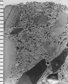
Figure 8-1 EXCESS AIR AT SURFACE OF CONCRETE (Top). Water was added to facilitate finishing. The elongated, angular coarse aggregate caused the mixture to be difficult to place. Notice the angular voids that exist down to a depth of 10 mm. The scale is in millimeters.
workmanship is the probable cause. Texture is important for any surface on which wheeled traffic travels. If the texture is insufficient, the petrographer should consider suggesting the sawing of grooves or, in the case of old concrete, replacing the layer by adding a textured overlay.
Report the condition of the texture on any surface on which traffic moves. Report any differences between the microstructure of the major portion of the paste and the paste adjacent to any exterior surface.
3. Note the sence of any foreign objects in the concrete. Such objects might be pieces of glass, wood, metal, or fabric. If such objects are common in the concrete under study, the cause is either a massive accident occurring nearby while the concrete was fresh, poor workmanship, or sabotage. Look for the evidence of any chemical reactions between such foreign objects and the chemicals of the paste. Some glasses will react with the highly alkaline paste and cause deleterious expansion. Fine aluminum fragments will cause the evolution of hydrogen gas, concomitant voids, and zones of weakness. Other substances may cause other reactions.
4. Report any portions of reinforcing bars or portions of the supports for the bars (called chairs) sent in the slice. Rust-colored portions of the lapped surface may indicate nearby corrosion of ferrous metal. Check the back of the slice, the opposing sawed surface, and the remaining (unsliced) portions of the specimen for corroded reinforcing bars and related material. Report their sence.
5. Examine the voids:
General appearance. Examine the appearance of the void system. It should be in conformance with the data obtained by the air-void analyses. Consider the number of voids and their size. If the voids are unusually small and numerous, the air content may be greater than it first appeared. If there is an apparent discrepancy, (1) check to make sure that the air-void analysis was conducted on the slice being examined and the analysis was performed properly and sad over the entire surface of the slice, or (2) request that the air-void analysis be repeated and/or conducted on additional slices. In the report to the client, discuss an apparent conflict between data obtained in accordance with ASTM C 457 and that seen with the unaided eye.
Shape. The hydrostatic pressures within the unhardened HCC paste cause the small voids to tend to a spherical shape. Most of these are the entrained air voids. They are sometimes mentioned in the literature as if the sphericity defined them. In extreme circumstances, even these small voids can become distorted by various forces. The shape and distribution of the various types of voids are important. Note any areas of unusual void angularity, and describe or label the location. Voids that are within the thin zone that becomes worked as the concrete is finished and textured can be quite angular. It is only the extremely small voids that maintain their individual integrity when they have been distorted by these procedures. The larger voids are usually broken and thus expelled from the surface, but many of the tiny ones remain, often angular and distorted. A minimum magnification of 100X is required to discern the sence, shape, and condition of very small voids. Rarely, retempering (see Appendix D) that occurs after the paste has started to harden and the individual voids have developed a "skin" will cause the majority of the medium and small voids in a concrete to take on an ovoid shape. Most commonly, the ovoids will have their long dimension vertical. This is a very rare condition and must not be considered necessary evidence of retempering. Much retempered concrete exists without the sence of any ovoid or otherwise distorted entrained air voids.
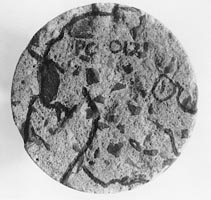
Distribution. When the voids are unevenly distributed (see Fig. 8-2), the location of large concentrations of voids can be important, particularly if the voids are consistently associated with certain other features, such as a particular type of aggregate. If these concentrations are thought to be an important indicator of the condition of the concrete, mark or otherwise make note of their location on the slice. (See the description of types of air voids in Table 6-1.) Concentrations of voids that do not appear to be related to any other specific feature may often be attributed to retempering or incomplete mixing.
Size. The overall void system (including the size of the voids) is measured and documented by the analysis of the air-void parameters as detailed in Chapter 6. However, if there is anything unusual about the size of the voids that can be seen with or without magnification, document it. For example, if one extremely large void (e.g., 50 mm by 15 mm) is sent in the slice being examined and it is decided that the void is not typical of the overall concrete, the area of the slice in which the void occurs is excluded from the area examined in accordance with ASTM C 457. Such a void should be measured, and its shape and internal surface described in the notes and report on the specimen.
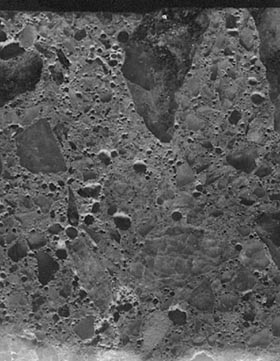
Figure 8-2 VOIDS OCCURRING IN BUNCHES. In this case, the bunching is apparently due to excess air-entraining admixture and incomplete mixing.
6. Examine the aggregate:
Lithology and mineralogy. Briefly describe the general types of rock and minerals seen in the aggregate of the HCC being examined. Include particle shape and color in the description. This description can be very helpful when you are trying to find a particular lapped specimen among all the specimens in the laboratory. If a particular type is sent in only a very small amount, it may be a contaminant and should be so noted. As an example, if the major portion of the coarse aggregate is crushed limestone and a few rounded pebbles of quartzite are sent, the quartzite is probably a contaminant and may indicate poor workmanship or an unusual incident occurring during mixing or placement. If the aggregate does not seem to be the aggregate specified in the design of the mixture as reported in the accompanying documentation, contact the client to resolve this inconsistency. Are the specimens received the ones that were meant to be sent? Is the documentation incorrect? Is there some other explanation? To achieve assurance in the identification of the aggregate, it may be necessary to request bulk specimens of the specified aggregate and perhaps specimens of aggregate from other sources; perform a detailed study of the frequency of occurrence of the various lithologies; determine particle shape, soundness, staining, natural rims, and cleanliness; and study the microstructure and optical properties of these aggregates in thin sections with the petrographic microscope. Take note of any deterioration of the HCC that is associated with any particular lithology. Such deterioration includes microcracking; popouts on the surface; reaction rims; and any deposits, particularly those that might indicate an expansive reaction (see Chapter 10).
Orientation. In some HCC specimens, the ferred orientation of the long dimension of the aggregate particles or general parallelism of flaky aggregate particles can be observed. Such orientation may indicate an abnormally high water-cement ratio, improper mixing or placement procedures, or both. Note any patches of paste that seem particularly devoid of aggregate and, conversely, any areas in which the aggregate is crowded together. These evidences of segregation of the unhardened concrete mixture may indicate an abnormally high water-cement ratio, improper timing of the placement sequence, or just generally shoddy workmanship.
Aggregate-paste ratio. An experienced concrete petrographer can usually tell at a glance if the aggregate-paste ratio is within the normal range of 75-25 to 59-31 (see Figs. 7-1 and 7-2). A more exact determination can be made with linear traverse, point-count, or image analysis methods. The precision of the determination of this ratio with linear traverse or point-count equipment is not well known. In the case of image analysis, if the area of surface examined is sufficient and resentative and the toning and other sample preparation procedures are carefully carried out, the results should be quite accurate.
Distribution. If the heavier and larger pieces of aggregate have settled to the bottom of the placement, it can usually be assumed that the segregation took place because the mixture contained an excess of mortar or the paste was too fluid because it contained excess water. Occasionally, it has been found that such segregation should be attributed to excessive vibration during consolidation of a mixture having more water than desirable. If there is a zone at the top of the placement that is nearly devoid of aggregate but the aggregate distribution appears normal in the remainder of the placement (as in Fig. 8-3), the cause of this distribution is probably the addition of water to the mixture after placement. This water may be added by a rainstorm or possibly even purposefully added to facilitate placement.
Cracks. During the study of cracks in the aggregate of hardened concrete, give continual thought and recognition to the fact that the aggregate has withstood the stresses of concrete fabrication. If the aggregate cracks are narrow (or do not seem to separate the aggregate into fragments) and the cracking seems to be in a regular pattern that echoes the surface of the aggregate, the cracking may be due to the intrinsic cleavage or parting of the aggregate. Shaly rocks and monomineralic aggregate particles of certain minerals might be good examples of this type of cracking. Cracks in the aggregate that do not appear to be due to the structural nature of the material of the aggregate, break the aggregate into separate pieces, or start in the aggregate and extend out into the paste may be due to reactions and forces to which the concrete has been subjected since hardening. For an example of this, refer to Chapter 10.
Coatings. Note any coatings on the surface of the aggregate particles (such as clay, iron oxide, or manganese oxide). These coatings may help identify the environment, source, and degree of beneficiation of the particles (Ozol,
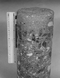
Figure 8-3 OVERWATERED CONCRETE. Rain and snow occurring after the concrete was placed caused overwatering near the surface (top). The aggregate sunk out of the overwatered zone.
1978). Such coatings, if porous, may act as reservoirs of water that cause weak zones of high capillarity in the hardened concrete.
Aggregate-cement reactions. Make special note of the sence of evidence of chemical reactions of the aggregate with the paste, i.e., rims, cracks, or reaction deposits, such as gel. Refer to Chapter 10.
Specialized aggregate materials. Refer to Appendix E for descriptions of specialized aggregate materials.
7. Study the paste:
Water-cement ratio. Estimate the water-cement ratio of the paste as either high, medium, or low by means of the following factors: (1) the observable texture of the paste; (2) the distribution of unhydrated cement grains; (3) the speed with which water sinks into a clean, oil-free surface; and (4) the manner in which the paste reacts, as observed with the microscope, when scratched and picked at. The petrographic evidences of the water-cement ratio in HCC or mortar are very subtle. Generally, they cannot be considered as hard firm evidence but may be used to indicate the necessity for a chemical determination of the cement content. Further details may be found in Chapter 9. Because of retempering (see Appendix D) or other mixing conditions, HCCs may have areas of low water-cement ratio and areas of high water-cement ratio in the same placement and even in the same specimen or slice. The strength of the HCC will depend on which type of concrete is most valent and most continuous through the mass.
Discolored areas. Take special note of areas of the paste that are a different color than the remainder of the paste. If the concrete mixture contains GGBFS, is quite young, and has been kept moist and the dark areas are a dusky bluish green, the areas of concern are probably nothing more than the wetter zones of the GGBFS-bearing HCC that are commonly this color until the material has dried and oxidized for the first time (Mather, 1957). Later moistening of GGBFS HCC will not recreate the color. Areas of a darker color than the major portion of the paste are probably zones with a high cement content and hence a lower water-cement ratio and were probably formed before all the water was added. If sufficiently hydrated, these areas may be very strong. If dry cement is encapsulated in these areas, it will have very little strength and the area will be a zone of weakness. Such areas may indicate retempering (see Appendix D) or improper mixing. They occur in two general types: (1) as coatings on and in reentrant angles of the aggregate particles, and/or (2) as knots or blobs of various sizes in the main area of the paste (see Fig. 6-3). If such areas are sent, mark the slice in such a way that a number of these areas will be noticed in a photograph. Occasionally, there are zones near the aggregate that are made up of cement that contain little water. These are caused by moist aggregate having come in contact with dry cement and having picked up a cement coating (see Fig. 8-4). If these coated aggregates are used in a concrete mixture, the very outside of the cement coating becomes moistened in its new environment; if the coating is thick, the inside can be served in a dry condition. If this concrete becomes subject to stress before water permeates the cement shells and hydrates them, these dry cement coatings will be a zone of weakness.
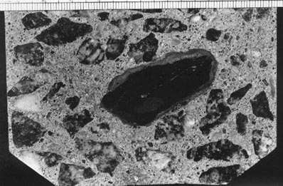
Figure 8-4 CEMENT COATING ON AGGREGATES. Damp aggregate came in contact with dry cement and picked up a layer that did not become hydrated. This layer is much denser than the zone surrounding the aggregate in Figure 6-3. Actual size.
Knots of cement (see Fig. 7-3) may be caused by water reaching the cement before use or by certain batch procedures. These knots can be so large and dense that they may be mistaken for aggregates. These areas are usually rounded by the action of the mixer. If a large portion of the cement is caught into balls or aggregate coatings, the remainder of the concrete will be depleted in cement and will have a high water-cement ratio and be weak. Variations in the color of the paste may indicate variations in the water-cement ratio (see Chapter 9). If the surface of the slice is rusty looking, it may be because the slice, while it contained a little water, was allowed to set for many hours on a nonmoving iron lap. Question the support staff concerning this and, if necessary, remind them that laps become pitted by rusting and then must be demounted, resurfaced or replaced, and remounted on the motor assembly.
Carbonation. Carbonation of the paste may be indicated by very slight color or textural variations within the paste or differential absorption of lapping oil. Occasionally, a narrow zone of the paste that is nearest to the carbonated area has been depleted of calcium hydroxide and is sufficiently porous to absorb a larger amount of lapping oil. This absorbent area may be seen as a dark line before the slice is completely oil free. Lightly etch the portion of the slice suspected of being carbonated (see 5.2.3).
Carbonation is most valent near the surface, along cracks, along "cold joints," and at cracks and aggregate boundaries. Carbonation is a process wherein certain constituents of the HCC paste chemically combine with the CO2 of the atmosphere. The calcium ions become part of the mineral calcite: CaCO3. Ca(OH)2 within the affected zone may completely alter to calcite. Some loosely held calcium ions in the calcium silicate hydrates of the cement paste alter to fine crystals of the carbonate minerals, mostly calcite. When the paste is treated with acid (see 5.2.3), the CaCO3 dissolves with effervescence. The uncarbonated paste is very soluble in the acid, and often the carbonated zone (now with calcite removed) appears porous but remains higher than the etched uncarbonated paste. After acid treatment, the portion that had been carbonated is usually cream or white in color. There is often a ridge of especially high relief at the line of contact between the carbonated area and the uncarbonated area (see Fig. 5-4). If the etching does not clarify the difference between carbonated and uncarbonated paste, fabricate thin sections for examination with the petrograpluc microscope. The high birefringence and the fine crystallite size of the products of carbonation, when viewed through crossed nicols, will indicate the sence of this alteration of the paste (see Figs. 13-8 and 13-9).
Cementitious particulate admixtures. Examine the paste for evidence of any cementitious materials other than portland cement. Fly ash can often be seen on a finely lapped slice of the specimen. Consider using an acid etch (see 5.2.3) to enhance the visibility of the fly ash (see Figs. 8-5 and 11-3). Some of the particulate admixtures of cements, such as GGBFS, cannot be seen on a lapped surface but may be detected in a thin section when studied with the petrographic microscope. GGBFS can be suspected when the color of the concrete is either mottled with the dark blue-green or is the light cream color associated with aged GGBFS concrete, but the GGBFS particles can be seen only in thin section. Particulate materials other than portland cement are discussed in Chapter 11.
Cracks at aggregate bond. Bond cracks are the narrow
separations occurring at the bond between the coarse aggregate and the paste.
Mark bond cracks by placing a small arrow on the aggregate. These separations
are particularly common with quartz-rich rock and gravel aggregate. Water
has an affinity for the quartz surface, and this layer of water may remain
on the aggregate uncombined with cement as the cement hardens around it.
Aggregate surfaces that attract water are often called hydrophilic. Surfaces
that repel water are called hydrophobic.
These bond cracks are more apt to occur in mixtures with a high water-cement
ratio. The layer of water attracted to the aggregate creates a boundary
void that often becomes filled with calcium hydroxide. Pockets of calcium
hydroxide are not as strong as calcium silicate hydrate, and thus weak zones
are created. In very old porous concrete subject to the action of running
water or ground water, calcium hydroxide in bond cracks may leach out and
leave an empty boundary crack.
Conflicting evidence exists concerning the valence of bond cracks in concrete containing expanded aggregate. In some, the aggregates seem to have developed a surface that repels water and makes a tight bond with the cement paste. In others, they seem to have developed as many, if not more, bond cracks as do quartz gravel aggregates (see Appendix E). Be continually on the alert for bond cracks and for any means of explaining their existence.
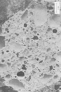
Figure 8-5 FLY ASH PARTICLES ON SURFACE OF LAPPED SLICK OF CONCRETE. They can be recognized by their glassy interiors. The light lighter colored fly ash is marked with arrows. The black fly ash is encircled. If the slice was etched, more fly ash particles would be detected.
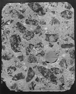
Figure 8-6 CRACKS AT BOND BETWEEN AGGREGATE AND PASTE (See arrows). In this instance, the bond cracks occur most frequently on the underside of the aggregate and, therefore, can probably be attributed to bleeding or poor consolidation
Bond cracks can be serious zones of weakness and contribute significantly to permeability (see Fig. 8-6).
Cracks within paste. Interior cracks in concretes that can be easily seen with the unaided eye are usually observed only in HCC that has been badly deteriorated by structural cracking, drying shrinkage cracking, plastic shrinkage cracking (see Chapter 4), alkali-aggregate reactions (see Chapter 10), or freezing and thawing (see Fig. 8-7). In the early stages of deterioration, they were much smaller. The interior cracks that become visible with close observation and with magnfication are called microcracks. Note all cracks within the paste. Microcracking and similar fine details are very difficult to see on a rough surface and usually cannot be observed on anything but a well-prepared finely lapped surface. Sometimes, the microcracking seen on a finely lapped interior surface will indicate the general location of the cracks on a nearby rough exterior surface. The thinner the slice, the more relationship will be found between the nearly invisible surface microcracks and the microcracks found on the lapped surface (see Fig. 8-8). The field of view seen through a microscope is very limited, and it is very difficult to construct a mental image of how one feature relates to another and be constantly aware of which portion of the specimen is under observation. A crack seen in one view may be followed across the specimen until it disappears, gets to the edge of the specimen, or abuts another feature, but the overall relationship of all cracks to each other can be obtained only by marking the cracks with ink and examining the specimen without magnification.
Figure 8-7 TYPICAL CRACKS DUE TO FREEZING AND THAWING.
Such cracks occur in non-air-entrained concrete. Cracks are emphasized with
ink.
 |
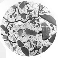 |
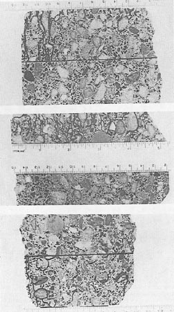
Figure 8-8 MICROCRACKS. A. Smoothly lapped surface with ink-marked microcracks. B. Wearing surface near view A. The cracks were followed over the edge of the slice. The crack pattern seen in view A was used to guide the finding of the cracks in view B. The crack lettering system allows comparison of the two photographs. Study these with regard to the fact that these views back up to each other.
The procedure for marking microcracks in the paste is as follows: While viewing the slice with the stereomicroscope, carefully mark the microcracks with a pen. Use the movement of the ink as it follows the minute cracks by capillary action to find all the connections between microcracks (Walker, 1988). Despite many years of experience, I have to teach my eyes what a microcrack looks like each time I do this task. At first look, I see very few microcracks, but as I start to study the few I see, more and more of them become visible. The visibility of microcracks depends a great deal on the angle of the illumination and the angle of viewing. As the specimen is turned and moved under the microscope, more and more cracks become visible. The mind and eyes become concentrated on the view in the microscope, and the hands become totally engaged in the tasks of marking and moving the slice of HCC. Thus, a sort of hypnotic state is created that leaves no part of the mind free to relate the area being marked to a larger view of the slice as a whole. (I find I cannot talk to anyone or truly listen to conversation without pulling myself away from the microscope.) Many operators find that they are quite startled when the crack being marked extends to the edge of the slice and the crack falls into oblivion.
When control or other comparison specimens of HCC are available, mark the microcracks in at least one slice of the specimens of the control concrete and one slice of any specimen of an intermediate degree of distress (see Appendix B).
This method can be very time-consuming if there is a great amount of microcracking. Moving the slice of concrete under the microscope in an effort to check and mark the cracks and the connecting cracks of the total area can be a seemingly endless task. To get the work done in a reasonable amount of time, a possible procedure is to mark off a randomly selected portion of surface on each slice to be examined and comprepared. The size of the portion should be governed by the uniformity of the cracking and its frequency (2 by 2 in. might seem like a lot of area when magnified). Do not use a pen to mark off the portion. Ink may follow capillaries into the area to be examined. Use a narrow adhesive tape or a soft pencil of a bright startling color. The marking of cracks and other important features can then be performed on these smaller portions of the surfaces (see Fig. 8-9).
Once the microcracks are marked, the patterns of microcracking will be visible to the unaided eye and varied HCCs can be comprepared and photographs of the microcrack pattern may be prepared and used as evidence of the true condition of the HCC, as shown by Figure 8-10.
If the placement has been overlaid with another material, such as latex concrete, the client may ask if there is a crack at the bond line. In such a case, study a vertical lapped surface and mark all microcracks with ink. Often, any separation between the overlay and the substrate concrete is not at the bond line but is in the weaker material of the substrate (see Fig. 8-11). This just-below-the-bond cracking is often discontinuous, but freezing and thawing and traffic may well cause complete delamination. This type of cracking indicates that more of the substrate should have been removed before overlaying if maximum durability was to have been achieved. Report all cracks.
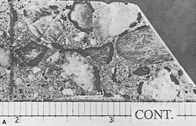
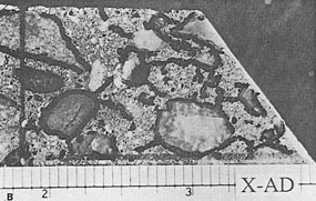
Figure 8-9 FINELY LAPPED SURFACES OF BEAMS TESTED FOR RESISTANCE TO FREEZING AND THAWING. The mixtures were identical except that the mixture shown in B contained an experimental admixture. The portions examined are of a similar size. The scale is in inches.
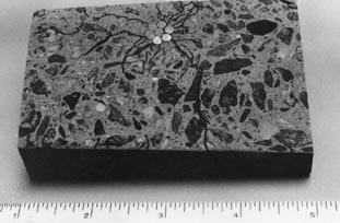
Figure 8-10 LAPPED SURFACE OF SLICE OF CONCRETE CONTAINING REINFORCING CABLE. With the stereomicroscope, the specimen could be seen to contain many fine cracks, but the relationship of all of the cracks to the reinforcing cable could not be noted until the cracks had been marked with ink and the crack pattern examined without magnification. The field of view (the portion of the slice) seen at the magnification necessary for observation of the fine crack system is about the size of one wire of the cable. The scale is in inches.

Figure 8-11 CRACKING JUST BELOW BOND IN CONCRETE WITH LATEX CONCRETE OVERLAY. Notice that the vertical crack in the substrate continues through the latex concrete and is expressed at the wearing surface.
All the notes produced during the examination of the slice should be reviewed, and all the marks that are intended to be visible in photographs should be made permanent and clear enough to be recorded in a photograph. If they are not, they should be enhanced.
| CAUTION: Most inks begin to fade after they have been in contact with HCC paste for a few days. Therefore, obtain any photographs promptly and make any necessary assessments of the condition of the concrete within a day or two. It is not known whether this fading is more rapid on young or old concrete or if it is due to ionic movement of the ink (sinking into and being distributed in dilute condition throughout the HCC) or by a chemical reaction. |
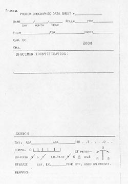
Each exposure should be recorded in a notebook or file expressly designed for such data. Data that will aid in improving future photographs should be included: (1) record the illumination and the adjustments on the light meter or shutter control, and (2) record the ground cloth and background when appropriate. A system of identifying all negatives should be devised and this identification recorded with the negatives, on any archive prints, and in all notes concerning the photographs or specimens. Figure 8-12 is a sample of a sheet used in the VTRC stereomicroscopy photograph notebook.
The photographs may include the entire slice or small areas of the slice may be recorded as enlarged by a camera lens or enlarger. Such photographs should be included in any important final report; they will be invaluable in any legal controversy. A permanent record should be made in the file of roll and frame numbers or photographic file numbers.
Important features that are visible only with magnification should be recorded in photomicrographs so they can be easily discussed with the client. A record of their appearance should be included in the data file on these specimens. Such pictures can be taken with a camera on the upright port of the stereomicroscope (see Fig. 2-16). REMARKS: