U.S. Department of Transportation
Federal Highway Administration
1200 New Jersey Avenue, SE
Washington, DC 20590
202-366-4000
Federal Highway Administration Research and Technology
Coordinating, Developing, and Delivering Highway Transportation Innovations
 |
| This report is an archived publication and may contain dated technical, contact, and link information |
|
Federal Highway Administration > Publications > Research > Structures > Covered Bridge Manual |
Publication Number: FHWA-HRT-04-098 |
Previous | Table of Contents | Next
This chapter deals with the issues related to determining member forces within the bridge and their associated stresses. The initial discussion focuses on the overall analysis of the truss, and later subsections deal with components of the floor system and bridge bracing. Chapter 13 discusses issues related to comparison of the calculated stresses with allowable stresses.
Heavy timber trusses behave much differently than more common, heavy steel trusses. Members in timber trusses are primarily subjected to axial forces, as in all truss structures, but they also are subject to substantial additional stresses from bending and shear forces. The member dead load contributes some shear and bending response, but floor beams at intermediate panel points and members continuous through connections also generate internal shear forces. A final and major contributor to these nonaxial forces is the inherent eccentricity found in many traditional timber joinery connection layouts. Unlike steel trusses, where the connections are laid out to include a theoretical intersection point for member centroids, thereby minimizing eccentricities, heavy timber truss joinery often does not provide for a common point. The original builders did this for some good reasons. Traditional joinery involves removing material from at least one member at each joint to craft a connection to another member at that joint. This represents an inevitable compromise in the member capacity. The art of designing and detailing traditional timber joinery lies in mitigating and balancing the detrimental impact of removing wood fiber from the various members involved. One classic way to balance the damage is to spread out the various members or introduce some minor eccentricities at connections between more than two members. Heavy timber truss designers distribute the damage and create a better structure, one with stronger joints between two members at a time, spread out along the length of at least one of the connected members.
To a large extent, steel trusses evolved from timber trusses specifically in ways that not only simplified the construction, but also in forms that simplified the analysis and design of heavy trusses. The connections in steel trusses, idealized with their theoretical work points (that is, where member centroids and forces are concurrent), can be analyzed for axial forces only and sized accordingly. Even rigorous computer analytical methods that include local bending caused by the member self-weight and minor inherent eccentricities-in combination with the axial forces-still usually result in stress levels that are acceptable in that same structure. The temptation to do more sophisticated modern analyses, without realizing any particular advantage, demonstrates the original advantage that steel trusses offered designers in being readily analyzed with axial forces only.
Another way to describe this is that heavy timber trusses might be more accurately modeled as frames. Frame analysis is usually performed with the help of modern software. Unfortunately, the classic hand analysis methods of moment distribution and virtual work have all but passed. Evaluating heavy timber components and structures under load combinations and variable durations can be time-consuming and tedious, even with the help of contemporary methods. Further, in many instances, the overpowering complexity of typical computer analysis output can lead to inappropriate simplification or rationalization. The thoughtful analyst may conclude that the assumptions made in the course of modeling a heavy timber frame/truss for computer analysis may introduce uncertainties well within the resolution of the professed results.
To illustrate this point, figure 89 provides an example of frame connections of a Burr arch. Note how the diagonals intercept the posts at a substantial distance down from the top chord. Although the clutter of the various elements hide it, the same geometry exists at the bottom of the posts. This is quite different from a conventional pin-connected metal truss.
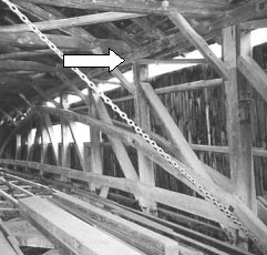
For these reasons, it is often a good idea for the modern analyst to return to the basics of truss analysis and investigate a timber truss structural behavior on the basis of axial forces only, assuming the truss to have theoretical and concentric work points. With the relatively simple results of this large-scale analysis, specifics of individual elements subjected to larger combinations of different forces and stresses can be superimposed for particular investigation.
As an example, a timber truss configuration patented by Colonel Stephen Long in 1830 is assembled from all timber components, with main diagonals and counters in each panel. The verticals of the Long truss are subjected to axial tension forces and substantial bending stresses, due to the eccentric loading in the diagonals relative to the location of the chord forces. The Long truss can be analyzed quite rapidly with manual methods, using the method of sections or method of joints, as long as the analyst is also prepared to temporarily neglect the action of the counters.
Certainly, there is a place for more refined analysis, but the basic analysis of a covered bridge does not have to be particularly difficult or complex.
As discussed above, heavy timber trusses can often be analyzed adequately by using a simplified model of the structure. The typical covered bridge longitudinal truss is usually built with the same depth and the same size chord elements over its span. Given this prismatic layout, determining the maximum chord force can be as simple as evaluating the mid-span moments and considering the bridge as a simple and single-span structure. With these simplifying assumptions, the maximum chord force for a statically determinate truss is simply the centerline moment in the span, divided by the vertical distance between the chord member centroids.
Another simplification that can be very useful when evaluating covered bridge trusses is that associated with using a plate girder analogy. The longitudinal trusses can be idealized as deep girders with large holes in their webs. With this simplified model, the flange forces in an idealized plate girder represent the chord forces. The section properties of the plate girder substitute are determined from the areas and vertical separations between the various elements of the chords and the parallel axis theorem. Although this plate girder simplification is just that, it nonetheless is quite adequate for at least the preliminary evaluations of a heavy timber truss.
When a more exact solution seems justified in analyzing a timber truss, a computerized approach may be adopted. Most common modern software uses a finite element methodology. This software can use complex individual elements to model the various components in a timber truss. The individual elements may be the size of a single truss element or may be the size of die used in a board game. Typically, the smaller in size (and greater in number) the elements, the more accurate and precise are the analysis. While this analysis is not inherently difficult and is being offered in more user-friendly versions all the time, it nonetheless remains crucial to properly model support conditions and connection behaviors. It is the connections that can make the computer model so complex.
For example, the lattice members in a Town truss bypass each other, with two or three pegs in single shear between the layers of planks at each intersection. The accurate way to model this is to have both planks pass through a doubled node at each joint and then introduce a dummy member between the two plank nodes. This dummy member simulates the spring interconnection between the two planks. The analyst would properly try to model the peg connection with shear element and rotational springs, taking a reasonable guess at the peg pattern stiffness.
Because these sophisticated models can rapidly become overwhelming, even for today's hardware, it is still quite common to exploit structural symmetry and prepare models of only portions of the entire bridge-perhaps a half or a quarter of the structure. Then it becomes particularly important to model the support conditions properly at the artificial internal interfaces. Further, it is easy to become confused with respect to symmetrical, asymmetrical, and anti-symmetrical loading conditions.
Figures 90 and 91 portray a three-dimensional computer simulation of a Town lattice truss bridge. Figure 90 demonstrates the complete stick-model of the structure in an unloaded condition. Figure 91 depicts a similar three-dimensional image distorted from the effect of loading. At the time of this work in the mid-1990s, it was believed that this computer simulation was the most complex ever undertaken for a covered bridge.
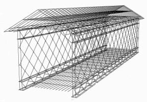
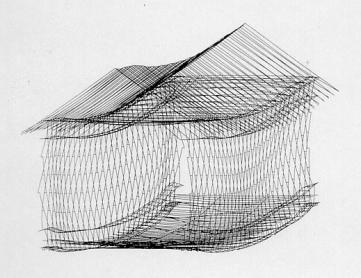
Figure 91. Three-dimensional image of computer simulation-distorted from load.
The next step in assessing the validity of any theoretical analysis involves comparing the output of the computer simulation with the measured behavior of the real structure under actual loads. One simple validation check involves comparing (1) the measured deflections in the structure at specific locations while the structure is loaded with a vehicle of known weight and configuration against (2) the computer model's predicted deflections at the same points and under the same loads. However, even if the deflections compare favorably, this does not assure that the actual forces in the structure are equal to the computer predictions for the same forces. Strain gauges have been used for a long time to measure stresses and forces in metal structures. They have also been used, albeit less frequently, when establishing structural response in concrete structures. Strain gauge measurements on full-size members in heavy timber-covered bridges are not common; however, it is possible that future work in this area will allow comparisons between computer predictions and field verification.
For many of these reasons, designers and analysts should carefully consider whether to attempt a refined analysis of the structure. It is a slow process and can be costly. However, refined computer-aided analysis can be very useful and worthwhile, in some instances, such as:
The most prevalent surviving covered bridge truss type is still that supported by Burr arches, a combination summarized as a multiple kingpost truss with a superimposed arch. There are interconnections along the structure's span, between the arch on either side of the sandwiched truss, often consisting of a single bolt in double shear at each post through the arches. Hence, the two trusses and the arches share the total loading on the bridge. Common questions are: "What part of the assembly carries what share of that total load? Do they each support half of the load? If not, how much of which load type is carried in each element, and why?"
Some believe the original builders intended the truss to support all applied load, i.e., the arches provide only compression buckling resistance for the truss. Others believe that the truss was intended to support only dead loading, while the arch was there to support live loading. Either assertion can be supported.
Solving for load sharing within this structural type without a computer is tedious and not especially practical. However, using a computer program is only reasonable if performed carefully. Many Burr arch structures exhibit significant distress at the bolted interconnections between the arches and truss posts, indicating that one element or the other is not sufficiently strong to carry its intended share of the load. If the connection is distorted or failing, then the stiffness properties of the connection itself must be carefully selected and modeled for the computer analysis to have any real relevance.
To further complicate matters, the classic Burr arch involves components that bear against the bridge abutments. This introduces the issue related to the abutment stability while resisting the significant thrusts. If the abutments shift under the arches' thrust, then the thrust is relieved, and the truss member forces are redistributed. There are other modified Burr arch structures in which the arch is not supported by a thrust block at the abutment but instead terminates at the bottom chord. If the connection between arches and lower chord is adequate, the arch can be considered "tied." If the tie connection fails, however, the arch cannot offer much load support for the structure, but tends to contribute only in-plane bending stiffness and out-of-plane buckling resistance.
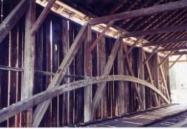
This combination of timber truss with connected arch components is probably one of the more difficult supporting systems confronting covered bridge engineers. Careful review, inspection, and investigation of a number of such structures indicate a lot of variability, making generalizations impractical. One very critical and difficult modeling assumption involves the stiffness of the interconnection between the arches and the truss. In any case, each of these bridges deserves careful review and evaluation. An example of a heavy timber Burr arch with its sandwiched truss is shown in figure 92. Figure 93 presents an example of a timber truss with a lightweight asymmetrical arch. It is not clear what, if any, assistance this arch provides to the truss.
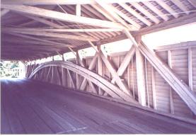
Figure 92. A heavy timber Burr arch-Wehr Bridge, Lehigh County, PA.
As introduced in chapter 7 in the section, "Bolster Beams," bolster beams are often so substantial that they can provide some support to the truss beyond the face of the abutment (see figure 94), thereby effectively shortening the theoretical span of the truss. Figure 95 provides an example of a concrete bolster.
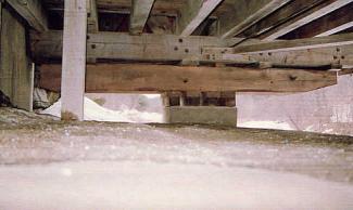
Figure 94. Large bolster beam supported on bearing blocks-Hall Bridge, Rockingham, VT.
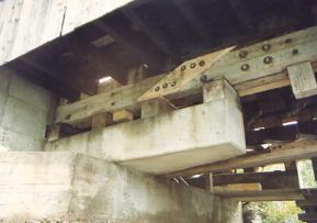
Figure 95. A bolster formed of concrete-Village or Great Eddy Bridge, Waitsfield, VT.
The conservative approach to this situation is to neglect the effect of the bolster and proceed with the analysis as if the bolster did not exist. In some instances, however, such an analysis may indicate the need to reinforce or replace truss elements. In that case, it may be appropriate to further consider the potential benefit of this element. Each installation of this type of element will be unique, and no general rules of thumb are available.
Analysis of floor systems is generally simpler than for truss systems, yet the results can still be frustrating, because the results often indicate that the floor components may be overstressed when they are able to withstand daily loading without apparent distress. Because covered bridges come with a number of floor system configurations, the following sections discuss individual components of the more common configurations found in most covered bridges.
The transverse floor beams, spanning between the longitudinal trusses, are the principal members involved in supporting vehicle loads and transferring the live loads to those trusses. An initial dilemma in their analysis involves establishing the span length for the floor beam. For those floor beams that are supported by a truss configuration with multiple chords, one might choose the shortest distance between innermost chords and minimize the bending stresses in the floor beam, or choose the longest distance between outermost chords and be conservative with floor beam stresses. Some analysts try to establish a reasonable bearing length at each support and use the centers of those bearing areas to set the floor beam span. While this is reasonable, it relies heavily on precisely cut bearing faces on the beams and surfaces that are perfectly level and planar on the tops of the truss bottom chords. There are always exceptions to any rule, but a good generalization is to use the distance between the centers of the trusses as the theoretical supported span length for the floor beam. Beginning with this assumption, the results can be evaluated later for their sensitivity to modest theoretical changes in the support location.
The next issue in evaluating the floor beams involves the live loading axle distribution to these beams (note that the floor dead load forces and accompanying stresses are rarely significant in traditional bridges). The AASHTO specifications offer specific guidelines for the longitudinal load distribution factor, depending on the type of deck system spanning between floor beams. Table 3.23.3.1, titled "Distribution of Wheel Loads in Transverse Beams" (AASHTO's Standard Specifications), provides a range of values from S/4, for a common longitudinal deck plank system, to S/5 for a bridge with nail-laminated or glue-laminated decks, 150 mm (6 inches) or more in thickness[2].
Because the results can be variable, this load distribution value has been the subject of intense debate among bridge engineers for a long period, and research continues on the topic. An analytical evaluation of any floor beam might imply that its capacity is a certain number of tons, although the floor beam has been supporting vehicles successfully with axle loading of substantially heavier amounts for an extended duration. The accuracy of the AASHTO load distribution factors is just one contributor to the gap between theoretical analysis and actual experience.
Covered bridge practitioners should be aware of the issue of distribution factors and are encouraged to keep apprised of any future improvements to AASHTO guidelines for axle loading to transverse floor beams.
In steel or concrete floor beams, bending stresses often control the allowable live load capacity over those limits posed by shear stresses, but shear is an important issue in any timber design and should be checked. Recall that the NDS timber specifications (as discussed in the section "Shear Force" in NDS Chapter 3) allow the analyst to neglect any concentrated loads (wheels) that are located within a beam depth of the beam support. Loads this close to the supports can be assumed to pass directly through to the rigid supports, without inducing any transverse shear stresses. Subsection 13.6.5.2, "Actual Stress," in the AASHTO Standard Specifications for Highway Bridges, allows vehicle loads to be neglected if within three times the depth of the beam.[2] This is an important distinction for those involved with covered bridges.
Builders often notched the undersides of these floor beams at the beam's support to insert the beams or level the top surfaces of slightly varying beams to support them on slightly uneven surfaces. The shape of the top corners of some floor beams was also reduced, especially those that penetrated the web components of a Town lattice truss. The NDS specifications contain guidelines on the handling of lower face notches, as they relate to a reduction in the capacity of the members. The NDS shear stress factor functionally penalizes for the notching-removing half the beam quadruples, rather than doubles, the shear stress. This is a simple way to account for the shear stress concentrations at the corners of the notch. The NDS limits the depth of any bottom notch to a quarter of the beam depth. Shear stresses in floor beams with top corner reductions and top notches can be analyzed with the traditional use of material mechanics. The British timber code also offers some guidelines on maximum allowable top notching and recommends tapers; these topics are treated very lightly in the American timber design guidelines.
Neither the NDS specifications nor most other traditional reference books include much guidance regarding reinforcing floor beams that have been subjected to significant notching and which, therefore, exhibit the attendant high shear stresses. Some contemporary timber construction books mention vertical through bolts and side plates. Another solution is simply to use a larger floor beam. Reinforcing the notched area may be a much more economical solution. However, the proper methods and analytical issues in these reinforcement schemes at end notches are not widely publicized.[7]
The theoretical shear capacities of transverse floor beams is regularly lower than their bending capacities, yet shear failures in floor beams are uncommon. Hence, as with the controversy involving the appropriate load distribution factor for floor beam analysis, shear capacity evaluations in heavy timber floor beams have been debated for many years. An appendix in the NDS specifications describes the two-beam theory of why timber beams that have sheared into two separate members can continue to carry significant load.[3] The footnotes to the NDS supplement of allowable stresses mention that shear stress increases with reliably smaller checking-as much as double the tabulated values with no checking. This reflects the fact that shear stresses have been reduced more than any other stress type over the past century. This primarily reflects the impact of kiln-drying dimensional lumber. The relatively thin members, when subjected to some occasionally harsh kiln regimes, are prone to large splits or checks at the ends where the wood dries fastest. These end checks coincide with the most typical location for maximum shear stresses in simple beams with uniform loading. Simply reducing the allowable shear stresses to cover these unfortunate kiln damages did not significantly impact dimensional lumber design, but it can be significant in the heavier timber designs. It is reasonable to affirm that large, seasoned timbers with vertical heart checks, if any, can be assumed to have minimal checks at their ends. Analysts should be comfortable with taking this allowable increase in the shear stresses. However, the AASHTO and NDS specifications have not yet refined current guidelines. Research continues in this area.
Another issue that deserves special consideration in floor beams is live load deflections. The AASHTO specifications indicate deflection limitations of timber floor elements in subsection 13.4, "Deflection."h[2] In many instances, a theoretical evaluation of live load deflection will indicate that a floor beam can have sufficient shear and bending strength to satisfy current specification requirements, but will not satisfy current deflection guidelines. Although this deflection issue has not received much attention in current literature, it is a common situation and one that warrants thoughtful consideration.
As introduced earlier in this manual in chapter 5, some timber bridge floor systems have been fitted with longitudinal members hung under, and connected to, the transverse floor beams. These members are labeled distribution beams within this manual, because they are added to help stiffen and strengthen the floor by reducing the load on any single floor beam. They do this by increasing the tendency to distribute the point load longitudinally, among more beams. The common connection between distribution and floor beams is a heavy U-bolt to clamp the distribution beam against the bottom of the floor beams, with a U-bolt at every other floor beam. Hence, as the vehicle axle traverses the bridge, it deflects a floor beam that, in turn, forces the distribution beam down, thereby pulling adjacent floor beams down in a way to spread the load over more than a single floor beam. These are, in a way, heavy suspended stringers. The distribution beams are often built from multiple parts of vertical planks. This made installation easier, while allowing the installer to stagger the individual butt joints to make the distribution beam fairly uniform along the full length of the bridge span. Figure 96 shows an example of a distribution beam system (refer back to figure 45 for another example).
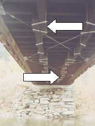
Figure 96. Distribution beam system-Worral's Bridge, Rockingham, VT.
A proper analytical analysis of this fairly complex floor system is challenging, and can be frustrating. One must carefully model the connection between floor beam and distribution beam to ensure a proper relationship when, in many instances, the installation has become loose due to shrinkage or wear of timber. A loose connection can significantly reduce the theoretical capacity of the intended helpmate. This grid overlay system, with its transverse loading, seems to merit computer analysis to assess load sharing between the different elements. This only makes sense when the floor system is modeled with the supporting longitudinal trusses. The heavy trusses are less than perfectly rigid under the live loading and their deflections further complicate the grid floor system behavior. This phenomenon is quite common when analysts confront their first heavy timber truss bridge. The components interact to such an extent, and in such complex ways, that the computer model can very quickly become too large and complex to analyze reasonably.
The AASHTO specifications do not address these distribution beams. An evaluation of distribution beams installed on 24 bridges was performed within the statewide study of 75 covered bridges in Vermont. That study concluded than one should neglect any potential benefit of the distribution beams, due to the commonly observed loose interconnections with the floor beams.
Although the connections are too loose for the distribution beams to offer demonstrable benefit to the bridge, these connections are still capable of holding up the distribution beams and thereby impose a dead load penalty on the floor beam capacity. The potential benefit of suspended dead load helping to damp vibrations in the floor system is esoteric enough to defy much further analysis. Accordingly, the Vermont report finally recommended removing the distribution beams during the bridge's next rehabilitation. Further, the connection detail modifications were not trustworthy enough to recommend their retention. Finally, because most of these members were added during the mid-20th century, they have no significant historic importance, so their removal should not concern historic preservationists.
Based on this discussion, distribution beams are not recommended for new covered bridges or in rehabilitation of extant covered bridges. Further, they should be removed from bridges during subsequent rehabilitation projects.
Analysis is relatively routine for floor deck systems that include a layer of longitudinal stringers. The support length typically is taken as the center-to-center distance between the supporting transverse floor beams. Guidance for the live load distributed to an individual stringer is provided by AASHTO in Table 3.23.1, "Distribution of Wheel Loads in Longitudinal Beams," of the Standard Specifications.[2] This load distribution factor is a function of the thickness and composition of the decking material spanning between the stringers. While there is evidence that the AASHTO distribution factors for such stringers are also conservative, the stringers in authentic covered bridges often have more theoretical capacity than do the supporting floor beams.
Although bending stresses traditionally control the capacity of stringers, shear stresses should be checked as well. As with the transverse floor beam, the NDS specifications allow the analysis for shear to neglect any live loading within the theoretical depth of the stringer from the support, while the AASHTO specifications allow neglect of vehicle loads within three times the depth of the stringer.
The very wide range of timber decking configurations found in covered bridges makes it difficult to generalize about this topic, although a few decking types are common enough to mention specifically. Longitudinal decking that spans between transverse floor beams may be flat and very heavy plank construction, nail-laminated planks on edge, or glulam panels. The AASHTO specifications provide guidance about these load distribution and support spans in these decking types in subsection 3.25, "Distribution of Wheel Loads on Timber Flooring."[2] Issues related to both bending and shear stresses are similar to those covered in the discussion above for stringers and floor beams.
One further complication when evaluating timber decking is the fairly common sacrificial running planks on top of the main decking. Although the AASHTO specifications do not offer any guidance regarding the effects of these planks, it is recommended that the structural contributions of these generally light planks be neglected in analyzing the floor system.
Bracing analysis is not covered much in texts. Most bracing is installed in covered bridges to help keep the structure aligned and to counteract forces that might realign the members. The major force driving the bridge away from straight and plumb is lateral wind loading.
Many classic and basic structural engineering texts discuss force analysis in the wind bracing systems used in steel through trusses.[14,15] For the basic single-span structure, horizontal wind loading is divided evenly between the load against the top chord and the load against the bottom chord. The wind loads applied at the bottom chord level are transferred directly and longitudinally to the abutments, through a bottom lateral system (or the deck itself, as a diaphragm). Most floor decks can provide ample lateral load strength without an additional bracing system, provided that there are good connections to the truss. The wind load that is applied to the top chord level, however, must also travel back and down to the abutments through some means, which often are not very strong and stiff.
There are two ways that the upper level applied wind loads are transferred out and down to the abutments. The difference is mainly in whether the lateral loads are transferred down to the deck level and then out to the abutments, or whether they are transferred at the upper level and then down all at once, at either the abutments or portal. The first analysis option is to evaluate the wind loading at the top chord level that is collecting to the ends of the span and then being transferred down to the abutments through very heavy portal framing. The lateral load accumulates along the span, heavily loading the end panels of the overhead X system. Many existing upper level bracing systems can carry the loads to the bridge ends, but only a very rare portal is sufficiently well-detailed and strengthened to handle this concentrated vertical load transfer. For this load-carrying mechanism to work as intended, the end sway frame system must be particularly well-connected and detailed. Depending on the connection details used for this type of system, the bracing forces may be considered to be tension-compression or compression-only, further complicating the design of this very heavy portal framing scheme.
The other analysis option is to evaluate the wind loading applied at the top chord level as being transferred immediately down to the deck level at each intermediate sway frame or truss vertical at panel points. This avoids building up a large and concentrated lateral force at the bridge ends. This scenario generates less force at any given sway frame, one that demands less of each, yet the same issues prevail regarding tension-compression or compression-only joint details in the braces.
Given these two profoundly different lateral load flow schemes, bracing sizes, connections, spacing, and details vary widely among historic covered bridges. In most instances, the bracing of an extant bridge can be justified analytically, and thereby improvements may not be necessary. Yet at other times, improvements may be indicated as being entirely necessary due to inadequate sizes and/or details.
Figure 97 provides an example of an extremely weak upper bracing system. In fact, there is no X lateral system and no knee braces, and the tie beams are skimpy. Figure 98 shows an example of an extremely strong upper bracing system. In addition to heavy tie beams, there is an X lateral system and strong knee brace frames connected to a heavy collar tie near the peak of the roof.
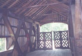
Figure 97. No X lateral system and no knee braces-Comstock Bridge, East Hampton, CT.
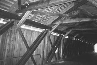
Figure 98. An extremely strong upper lateral and knee brace system-Hamden Bridge, Delaware County, NY.