U.S. Department of Transportation
Federal Highway Administration
1200 New Jersey Avenue, SE
Washington, DC 20590
202-366-4000
Federal Highway Administration Research and Technology
Coordinating, Developing, and Delivering Highway Transportation Innovations
 |
| This report is an archived publication and may contain dated technical, contact, and link information |
|
Publication Number: FHWA-HRT-06-103
Date: August 2006 |
||||||||||||||||||||||||||||||||||||||||||||||||||||||||||||||||||||||||||||||||||||||||||||||||||||||||||||||||||||||||||||||||||||||||||||||||||||||||||||||||||||||||||||||||||||||||||||||||||||||||||||||||||||||||||||||||||||||||||||||||||||||||||||||||||||||||||||||||||||||||||||||||||||||||||||||||||||||||||
Material Property Characterization of Ultra-High Performance ConcretePDF Version (2691 KB)
PDF files can be viewed with the Acrobat® Reader® CHAPTER 4. DISCUSSION OF RESULTS4.1 TENSILE BEHAVIOR OF UHPCFour small-scale experimental test methods were used to study the tensile behavior of UHPC. These test methods included the ASTM C1018 prism flexure test, the ASTM C496 split-cylinder test, the AASHTO T132 mortar briquette test, and the cylinder direct tension test. Individual test results were presented in section 3.4. In this chapter, the results will be combined and compared and the test methods and their applicability and practicality for UHPC will be discussed. 4.1.1 Summary of Experimental ResultsThe four small-scale concrete tension testing methods used in this research provided varied bodies of results. Table 35 presents the primary quantifiable results from the four test methods. Each test provided an indication of the tensile cracking strength of UHPC. The direct tension and prism flexure tests also provided an indication of the modulus of elasticity of UHPC. Finally, the prism flexure tests provided an indication of the postcracking toughness of UHPC. For reasons discussed in section 3.4.1, the third-point loaded UHPC prism with the 305-mm (12-inch) span is taken as the standard prism flexure loading configuration, and its results are presented in this section. The tensile cracking strength of UHPC is critical to the design of UHPC structures; however, it is difficult to determine experimentally. All of the four test methods provide realistic tensile cracking strengths that could be assumed to be accurate representations of actual tensile behavior. However, table 35 also shows that, for each curing regime, the tensile cracking strength can vary by approximately 3.4 MPa (0.5 ksi) depending on the test method used. For this reason, engineering judgment must be used to predict the true tensile cracking behavior. Table 35 shows that the results for the cylinder direct tension and mortar briquette test cracking tensile strength were generally similar for each curing regime. This similarity is not surprising, because both test methods are based on the uniaxial application of tensile stresses. The prism flexure results, after the application of the correction factor discussed in section 3.4.1.1, are generally slightly higher than the direct tension results. Note that without the correction factor, the prism flexure results would be approximately two times the direct tension results. Finally, the split-tensile results are approximately one-third larger for all curing regimes, a result that is not unexpected when comparing split-cylinder test results with direct tension results.(27) Direct tension results are normally more highly regarded than split-cylinder results. However, direct tension tests may possibly be disproportionately impacted by local heterogeneities as compared to the larger structures that they are supposed to mimic. Therefore, lower tensile cracking strengths may be reported than what would actually be observed in practice.
The results from these four test methods were combined together to determine the tensile cracking strength. The combining of these results takes into account the overall body of results, the number of tests, and the deviation of results from the average value. When these factors are combined, the tensile cracking strength of steam-treated UHPC is 9.0 MPa (1.3 ksi). The tensile cracking strength of untreated UHPC is 6.2 MPa (0.9 ksi). The tensile cracking strength of tempered steam and delayed steam-treated UHPC are both 9.0 MPa (1.3 ksi). These tensile cracking strength results can be compared with the compressive strength results discussed previously in this report. The bottom of Table 35 shows that the tensile cracking strength, fct, is approximately 5 percent of the compressive strength, fc', in all four curing regimes. Alternatively, the equation in figure 135 is frequently used to approximate a tensile strength from a given compressive strength. In this equation, the square root of the compressive strength is related to the tensile strength by a linear multiplier, x. In English units (psi), the UHPC that underwent the steam treatment has a multiplier of 7.8, the untreated UHPC has a multiplier of 6.7, and the tempered and delayed steam-treated regimes have a multiplier of 8.3. Figure 135. Equation. Concrete tensile strength approximation. The modulus of elasticity results obtained from the tension tests are also presented in the table. Given the limited number of direct tension tests completed, these results can be considered to be similar to the compression test modulus of elasticity results discussed in chapter 3. Although the untreated result is 11 percent higher, the remainder of the results are within 3.5 percent. However, the prism flexure modulus of elasticity results are generally between 10 and 15 percent higher than the comparable compression test results. This result indicates that the UHPC prism flexure tests tend to overestimate the modulus of elasticity as compared to the standard compression testing methods, because nearly all of the prism groups exhibit this behavior, regardless of cross section and loading configuration. The postcracking tensile behavior is much more difficult to quantify, but this research program has resulted in a number of both general and specific findings. The mortar briquette tests provide the most direct indication of the postcracking behavior. Figures 66 through 77 show the full load-displacement curves for all of the mortar briquette tests. First and foremost, these figures indicate that UHPC tends to display postcracking strength levels similar to its precracking strength levels. The table lists the average postcracking strength values, which are all within 0.8 MPa (0.1 ksi) of the mortar briquette first tensile cracking strength levels. Note, however, that postcracking behavior is very dependent on fiber dispersion and orientation. The small-scale mortar briquettes most likely did not accurately represent the large-scale tensile members for these two factors. Limited postcracking strength results are also available from the split-cylinder tests. These tests indicate that, under the biaxial state of stress present in this test configuration, UHPC exhibits significant postcracking load-carrying capacity. For each curing regime, the peak load carried after cracking is approximately twice the cracking load. However, the compressive forces paralleling the tensile crack in this loading configuration increase the fiber/matrix bond and thus contribute to the postcracking load-carrying capacity. Finally, comparative results were also obtained from the prism flexure tests. The results from this standardized test can easily be compared both within this study and with normal and fiber-reinforced concretes tested by other researchers. Comparisons with the standard toughness levels set in ASTM C1018 and with the results from other researchers indicate that UHPC exhibits very high postcracking toughness values. Specifically, all the UHPC curing regimes were at or above the stated fiber-reinforced concrete toughness upper limit for the values of I5, I10, and I20. Also, these tests indicate that a relatively uniform level of toughness will be achieved throughout the curing regimes. However, these results do not mean that all UHPC display identical postcracking load-carrying behavior, because the ASTM C1018 toughness measure relates postcracking to precracking behaviors and thus is biased by the precracking strength. 4.1.2 Summary of Experimental Test MethodsSections 4.1.1 and 3.4 describe the small-scale tension tests employed in this research program and the relevant results from each test. This section builds on those presentations to present and to compare the test methods. Test capabilities and the difficulties associated with completing each test will be discussed. The split-cylinder test is the simplest UHPC tension test to complete successfully. This test program has shown that consistent UHPC tensile cracking strength results can be obtained by following the ASTM C496 test procedure. The only addition to the test is the inclusion of a cylinder lateral expansion measurement and recording device. Thus, a measure of the tensile cracking strength of UHPC can be obtained using a standard hydraulic compression testing machine, a simple data acquisition system, and a pair of displacement transducers. Alternatively, an evaluation technique capable of detecting a crack in UHPC, such as ultrasonic inspection, could be used to note cracking in steam-based treated UHPC, thus eliminating the need for data acquisition and full-range transducers. Test results presented in section 4.1.1 indicated that conversion of the split-tensile cracking strength result to the overall tensile cracking strength result could be obtained by multiplying the split-cylinder result by a factor of 0.75. Unfortunately, the unknown postcracking stress distribution in the cylinder does not allow for the quantitative determination of any postcracking tensile behaviors. A slightly more advanced loading setup is required for completing the AASHTO T132 mortar briquette test. The test performed in this research program required a test machine capable of loading under crosshead displacement control and a data acquisition system capable of recording load and displacement readings throughout the test. The primary benefit of this test over the split-cylinder test is that it directly measures uniaxial tensile properties of UHPC. This benefit allows for a more accurate rendering of the UHPC tensile cracking strength. Also, this test method can provide some indication of the postcracking tensile strength of UHPC; however, the difficulties inherent in the casting of these small briquette specimens decrease the confidence in any postcracking strength results. As such, the benefits of this test over the split-cylinder test are marginal unless a qualitative verification of postcracking load-carrying capacity is desired. The ASTM C1018 prism flexure test is significantly more intensive with regard to testing equipment than either of the previous two test methods. To successfully complete this test, a test machine capable of loading under an external displacement transducer control is necessary, along with a data acquisition system to record load and displacement. Additionally, an electronic averaging circuit to combine the deflection results from the specimen can provide more consistent, uniform loading. The benefit of the prism flexure test is that it provides an indication of the tensile cracking strength, the modulus of elasticity, and an arbitrarily defined but widely used measure of the postcracking tensile toughness. Because a cross comparison between different fiber-reinforced concretes or concretes cast in different laboratories is important, this test can provide needed results that are unavailable through simpler test setups. However, as discussed in section 3.4.1.1, tensile cracking strength results from this test method must be corrected using an empirical relationship. The acquisition of pure tensile cracking behaviors from this test method is not possible. The final test method, the direct tension test, is the most difficult test to implement and also provides the most complete body of results. This method requires a test machine capable of loading under external displacement control, an electronic averaging circuit for at least three displacement transducers, and a data acquisition system to record the load and displacements. Additionally, a means of gripping the tensile specimen, such as the high-strength, high-modulus epoxy used in the research, is necessary. Finally, great care must be taken in the fabrication of the small-scale specimens to ensure that they replicate the regions in large-scale structures that are subjected to tensile stresses. If all these requirements are met, this test has the possibility of capturing the full tensile stress-strain or stress-crack opening behavior. These results would include the tensile cracking strength, the modulus of elasticity, the postcracking tensile strength, and the load-carrying capacity from tensile cracking through fiber pullout. The test program discussed in this report did not achieve the goal of successfully completing direct tension tests, and thus was not able to determine the full tensile stress-strain response of UHPC from smallscale tension tests. The selection of a particular tension test for UHPC must be predicated on the results desired. The tests discussed in this section could be used to meet certain needs, but other tests or modifications of these tests could also be used. For example, it is likely that UHPC used in structures will require a minimum level of tensile strength. As a quality control issue, a hydraulically operated test machine under load control could be used to ensure that the minimum level of tensile strength is achieved. This could be accomplished by an experienced quality control professional performing a mortar briquette or split cylinder test wherein the UHPC was required to hold a sustained stress level prior to the audible indication of tensile cracking. 4.2 LOCAL AND GLOBAL MECHANICAL FAILURE MODES OF UHPCUHPC exhibits a number of macrostructural mechanical failure modes. These failure modes can be categorized into three specific types: compressive, tensile cracking, and tensile fiber pullout. A fourth failure mode, the high-cycle fatigue failure of crack-bridging steel fibers, has been observed under special loading conditions but will not be discussed in this report. The compressive failure of UHPC can be considered to be similar to the compressive failure of any fiber-reinforced concrete. In general terms, UHPC fails under axial compressive load through lateral tensile expansion. This lateral expansion is partially restrained by the internal steel fiber reinforcement, thus allowing for a more ductile failure than may be expected. As with any concrete, higher-strength UHPC tends to fail in a more brittle manner than lower-strength UHPC. Compression failures in hundreds of UHPC cylinders were observed while performing the ASTM C39 compression test. The failure of any cylinder that underwent steam-based treatment was brittle, with a rapid load decrease occurring immediately after the peak load was achieved. Even as such, these cylinders remained largely intact with relatively few small fragments leaving the cylinder. The failure of the cylinders in the untreated regime occurred in a much more ductile manner. Some of these cylinders, particularly the ones with strengths above the average of 126 MPa (18.3 ksi), did exhibit brittle behavior. However, most of these cylinders failed through a continuous, nonabrupt decrease in load after reaching the peak. The failures of these lowerstrength (and less cured) cylinders were significantly more ductile and exhibited quantifiable post-peak behavior that was not achievable on a hydraulically-actuated load testing machine with the higher-strength cylinders. Finally, the compression testing of a 76-mm(3-inch) diameter steam-treated UHPC cylinder that did not contain any fiber reinforcement resulted in an extremely brittle failure with significant fragmentation of the UHPC. The tensile behavior of UHPC allows for continuing tensile load-carrying capacity across a cracked plane. The design of the structure will determine whether the tensile cracking of UHPC is a failure mode. Regardless, for the purposes of this discussion the UHPC behavior at this critical junction will be described. Similar to the compression failures described above, the tensile cracking of UHPC can be either brittle or ductile. Although these differences in behaviors were observed in all small-scale tensile tests, the differences were most clearly observed in the split-cylinder tensile tests. In these tests, the cylinders that had been subjected to steam-based treatments tended to exhibit a clear aural indication of first cracking and displayed discontinuous load-displacement behavior as the crack abruptly formed, then was arrested by the bridging fibers. Conversely, the untreated cylinders did not exhibit an aural indication of first cracking and sometimes displayed continuous load-displacement behavior at cracking. Also, the crack width at crack arrest tended to be larger in the cylinders that underwent the steam-based treatment, which was likely due to the higher tensile strengths at which cracking occurred. Final tensile failure of UHPC generally occurs when the steel fiber reinforcement begins to debond from and to pull out of the UHPC matrix. Because fibers are randomly distributed and oriented in the UHPC, individual fiber loads vary at any particular global load level. Mechanically, pullout occurs when the load carried by an individual fiber overcomes the ability of the UHPC to grip the fiber. Pullout by any fibers increases the load that other nearby fibers have to carry. Multiple pullouts in a specific location that require gross load redistribution through alternate load paths can be defined as fiber pullout failure. Fiber pullout across a plane perpendicular to the principal tensile stresses was the failure mechanism that concluded all small-scale tension tests. The fibers protruding from each failure surface tended to align perpendicular to the surface, likely due to the inelastic bending of each fiber at its exit point from the UHPC matrix as the crack widened and pulled the fiber straight across the crack. 4.3 EFFECT OF CURING PROCEDURE ON UHPC PROPERTIESOne of the primary focuses of this research program was to determine the effect that the application of a curing treatment had on the behaviors exhibited by UHPC. To quantify this effect, the majority of the research completed within the material characterization portion of this study included four different curing regimes. The curing regimes included the manufacturer-recommended steam treatment, a delayed version of the same treatment, a reduced temperature version of the same treatment, and an untreated case in which the UHPC remained in a laboratory air environment until testing. Table 36 presents a compilation of results from the material characterization study. The results provided in the table are average values that were summarized for ease of discussion. A full discussion of each portion of this test program is provided in chapter 3. The application of a curing treatment clearly impacts UHPC behavior. A comparison of the steam-treated and untreated regime results indicates that the application of the recommended steam treatment has a significant effect on some properties. In terms of mechanical properties, steam treatment will increase the compressive strength, tensile cracking strength, and elastic modulus. In terms of long-term stability, steam treatment will decrease creep and speed the realization of the asymptotic shrinkage, virtually eliminating any shrinkage after the treatment is complete. In terms of durability, steam treatment seems to decrease the permeability of UHPC, thus increasing its resistance to chloride penetration. A more durable mechanical matrix that is better able to resist abrasive forces is also created. The application of intermediate curing treatments, such as in the tempered steam and delayed steam regimes, also has a significant—although generally slightly reduced—impact on the UHPC behavior. While the compressive strength and elastic modulus are increased by these treatments, they both fall short of the level achieved with the full steam treatment. Interestingly, tensile cracking behavior enhancements seem to be similar regardless of the type of steam treatment applied. Note that the creep behavior is significantly enhanced by the delayed steam treatment, while it is only slightly enhanced by the tempered steam treatment. In terms of durability, the chloride ion penetrability is extremely low regardless of the steam treatment applied.
Another curing treatment procedure, illuminated during this test program, is slightly outside of the clearly defined boundaries of the curing regimes. In section 3.3.5, the effect of demolding cylinders in terms of their early age setting and strength gain was discussed in terms of compressive strength. These tests showed that demolding UHPC, and thus exposing it to a low humidity environment prior to sufficient setting and strength gain, could have a significant impact on the 28-day compressive strength. It is extremely important to wait until a sufficient strength level has been achieved before demolding UHPC and to keep UHPC in a moist environment during the continued strength gain. This procedure was not always followed within this material characterization study and, as discussed in chapter 3, some of the observed behaviors were reduced as a result. The overriding result of the entire UHPC curing treatment comparison is that, regardless of the curing treatment applied, UHPC exhibits significantly enhanced properties compared with standard normal strength and HPCs. The application of the steam treatment is clearly beneficial; however, this procedure is also not always necessary as long as the user is willing to accept decreases in strength, long-term stability, and durability. 4.4 EARLY AGE STRENGTH GAIN OF UHPCThe compressive strength gain behavior of UHPC is an important characteristic of the concrete. Results detailed in chapter 3 indicated that UHPC does not have any compressive strength for nearly 1 day after casting. Then, once initial set occurs, UHPC rapidly gains strength over the course of the next few days until over 69 MPa (10 ksi) of strength is achieved. At that point, the rate of strength gain decreases, but the strength gain continues until over 124 MPa (18 ksi) of compressive strength is achieved by 28 days. Figure 136 presents a compilation of the compressive strength data for the untreated cylinders tested between 1 and 56 days (the results are discussed in section 3.3.2). These results include both cylinders in the untreated group and cylinders in the other treatment groups that had not yet undergone their own steam treatment. Also, recall from section 3.6 that initial set tended to occur at approximately 15 hours, and final set occurred 2 hours later. A regression analysis was completed to fit a transition function to the data presented in figure 136. The delayed then rapid early age strength gain behavior of UHPC results in a somewhat complex approximating function. The Weibull Cumulative function, provided as the equation in figure 137 and plotted in figure 136, accurately describes the strength gain behavior for any time after 0.9 days following casting. This equation includes the time in days after casting, t, and the 28-day compressive strength in MPa, fc', with the result being the compressive strength at time t in MPa. The initial and final set times of UHPC can vary depending on the age of the premix and the environmental conditions, thus this equation may not be applicable to UHPC exhibiting different setting behaviors. Figure 136. Graph. Compressive strength gain as a function of time after casting. 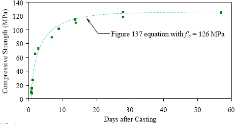
1 MPa = 145 psi Figure 137. Equation. Compressive strength at any age after casting.  4.5 COMPARISON OF CYLINDER AND CUBE COMPRESSION STRENGTH RESULTSThe cylinder is the standard concrete compression test specimen geometry used in the United States. This is understandable, because cylinder molds are inexpensive and the casting of concrete cylinders is relatively easy. However, as opposed to traditional concrete, UHPC cylinders cannot easily be prepared for testing. In any concrete compression test, the even and parallel loading of the ends of the cylinder is critical to achieving accurate test results. The high compressive strength of UHPC eliminates the possible use of end capping materials and predicates grinding or milling to ensure plane, parallel loading surfaces. Unfortunately, the equipment necessary to perform this end preparation on UHPC cylinders is not yet locally available to all quality control and testing departments. One method of eliminating the need for cylinder end preparation is to use cubes as the standard means to measure the compressive strength of UHPC. Cubes are cast with two pairs of plane, parallel faces, thus greatly simplifying the specimen preparation process. The primary drawbacks to the use of cubes are the expense of the molds, the unfamiliarity with the test methods, and the indirect nature of the results obtained from the test. In general, cube compression test results are higher than cylinder compression test results on the same concrete due to the aspect ratio of the specimens and the confining effect of the machine platens. To account for these differences, a strength reduction factor normally needs to be applied to a cube compression test result. This factor can vary significantly depending on many concrete properties, but has been reported to be in the vicinity of 0.82 for ordinary concrete and increases toward 1.0 as the concrete strength increases.(64) Section 3.3.4 presented the results from a series of cube and cylinder compression tests. Recall that the 51-, 76-, and 102-mm (2-, 3-, and 4-inch) diameter cylinders, as well as the 51-mm (2-inch) and 100-mm (4-inch) cubes were tested and that the series of tests were repeated three times on different batches of UHPC. If the 76-mm (3-inch) diameter cylinder is considered to be the control specimen, the results showed that the compressive strength exhibited by the 100-mm (4-inch) cube specimens ranged from 1.2 percent below to 8.0 percent above the control specimen strength. The strength of the 51-mm (2-inch) cube ranged from 4.6 to 6.1 percent above. These increases of less than 10 percent are sufficiently small; therefore, cube tests should be able to be used as a direct substitute for cylinder compression tests in some applications. Although most owners will probably require cylinder compression tests as the standard strength test result reported for the foreseeable future, the UHPC component fabricator internal quality control testing using the cube specimens would not be precluded. One additional finding from the results presented in section 3.3.4 relates to the size of the compression specimen (for either the cylinder or the cube). The results indicate that smaller specimens, particularly the 51-mm (2-inch) diameter cylinders and the 51-mm (2-inch) cubes, tended to exhibit larger standard deviations. The casting-based heterogeneities (i.e., entrapped air voids) in the UHPC that are proportionally larger in smaller specimens are likely behind these results. For this reason, the use of compression specimens that have a minimum dimension smaller than 76 mm (3 inches) is not recommended. 4.6 SHRINKAGE BEHAVIOR OF UHPCA significant portion of this research program has focused on the tensile behaviors of UHPC and the applicability of those tensile behaviors to structural engineering. Assurance of those tensile properties in a completed structural member is a factor of many things, including both casting/placing techniques and curing treatments. Another important factor is the formwork and its ability to restrain shrinkage forces. The test results presented in section 3.7 indicate that UHPC exhibits shrinkage behaviors that are somewhat different than those exhibited by normal concrete. Overall long-term shrinkage of UHPC is somewhat large, with an asymptotic value nearing 850 microstrain. More importantly, the results indicate that UHPC shrinks very rapidly in the 24 hours after the initiation of setting behaviors. This rapid shrinkage can include up to 400 microstrain of shrinkage during this time frame with a shrinkage rate of up to 60 microstrain per hour. The shrinkage continues at an increased rate as compared to normal concrete with 95 percent of its ultimate shrinkage occurring by 2 months after casting. These early age shrinkage behaviors are important to the successful casting of UHPC structural members, because UHPC will crack at tensile strains significantly below these shrinkage strains. Thus, the casting of UHPC must mitigate or eliminate shrinkage restraints on the cast member. For highway bridges, standard I-shaped girders are not particularly susceptible to restrained shrinkage cracking. However, in the casting of a member with restrained areas, such as a double-tee section or a box section, special care must be taken to allow for monitoring and the release of shrinkage strains. 4.7 LONG-TERM STABILITY OF UHPCThe basic premise behind the application of prestressing forces into concrete girders is that the application of an eccentric compressive axial force onto a beam will delay inelastic behaviors and increase the ultimate capacity. To achieve these goals, the prestressing forces must be maintained indefinitely. Time-dependent concrete behaviors such as creep and shrinkage can both negatively impact the maintenance of the prestressing force, thus reducing the enhancement provided by the prestress. This section addresses the general long-term stability of UHPC, including the creep and shrinkage behaviors that can be expected and the possible methods to alleviate those behaviors. In large-scale, prestressed concrete girder fabrication facilities, the time required to fabricate a girder from initial form setup to cutting of strands and removing the girder from the form is critical. This amount of time determines the turnover for the casting bed and directly influences the cost of each girder. In general, precasters want to create a rapid turnover, thus they are interested in stressing the girder as soon as possible after casting. The results of this method, for any concrete, are that the expected creep and shrinkage values will be larger and the prestress losses will be greater. The shrinkage behavior of UHPC has been discussed in sections 3.7 and 4.6. UHPC can be expected to undergo nearly half (400 microstrain) of its long-term shrinkage (850 microstrain) during the first 24 hours after setting. Also, steam treatment will hasten the achievement of the ultimate shrinkage value and will effectively stabilize the UHPC against further shrinkage indefinitely. For these reasons, delaying the stressing of the girder is clearly beneficial. The creep behavior is also influenced by the concrete strength at girder stressing. The long-term creep results from section 3.8 indicate that creep coefficients between 0.3 and 0.8 can be expected for UHPC that is treated according to one of the curing regimes. However, the prestress would likely be applied before any of these treatments are completed in a production environment. For this reason, the creep behavior at earlier ages, and thus at lower compressive strengths, is important. The early age creep testing presented in section 3.8.2 focuses on this behavior for UHPC that is still of relatively low strength. Creep at two compressive strength levels was investigated, namely 62 and 86 MPa (9 and 12.5 ksi). These results indicate that significantly less creep will occur after moderate increases in strength; however, the creep strains observed only 30 minutes after loading a 84 MPa (12.25 ksi) cylinder to 70 MPa (10.15 ksi) were still over 50 percent of the elastic strains from the initial loading. This 30-minute effective creep coefficient of 0.52 is quite high considering that the long-term final creep coefficient for a 114-MPa (16.5-ksi) UHPC loaded after 28 days of curing is only 0.78. Similar to the shrinkage results discussed above, the creep results indicate that delaying the stressing of the girder until higher strengths are achieved can be beneficial in terms of long-term prestressed girder behavior. These higher strengths and the better resistance to creep can come either from purely delaying the stressing as in the untreated regime or from steam treating the UHPC prior to application of the prestress. 4.8 MODULUS OF ELASTICITY OF UHPCBecause compression testing of cylinders is a frequently used quality control method for structural concrete, engineers often attempt to relate other characteristics of concrete’s behavior to the compression test results. Many researchers have performed work that focuses on the relationship between the compressive strength of concrete and its elastic modulus. This section compares the strength and modulus results of this test program with the results from predictor equations developed elsewhere. Note that this discussion is presented primarily in English units, as these correlation relationships are widely known in the United States in this format, and a conversion to metric units would lessen the relevance of the results. Recall that the modulus of elasticity testing was completed on compression cylinders according to the ASTM C469 test method. The results from these tests were presented in section 3.3. Table 37 summarizes the overall 28-day results from these tests for each curing regime along with the compressive strength values.
The American Concrete Institute’s Building Code and Commentary (ACI 318) provides two relationships for the modulus of elasticity.(65) The equation in figure 138 shows the first relationship wherein the square root of the compressive strength of concrete is related to the modulus of elasticity through a scalar factor. In this equation, both the compressive strength, fc', and the modulus of elasticity, E, are in psi. This equation was derived from, and is most relevant to, normal strength and normal weight concrete. Figure 138. Equation. ACI 318 approximation of modulus of elasticity. ACI 318 provides a second relationship for the modulus of elasticity wherein the unit weight of the concrete is included. This modification allows for estimation of the modulus of elasticity for concrete with a unit weight between 1,440 and 2,480 kg/m3 (90 and 155 lb/ft3). This modification of the estimation equation is important, because both the weight of the concrete and the modulus of elasticity are normally heavily dependent on the type of aggregate used. The equation in figure 139 presents this relationship in English units, with ρ as the unit weight of concrete in lb/ft3. Recall that the unit weight of UHPC is approximately 2,480 kg/m3 (155 lb/ft3). Using this unit weight, this equation would transform into an equation similar to the one in figure 138 with a scalar of 63,700. Note that the equation shown in figure 139 is also the relationship provided in the AASHTO Load and Resistance Factor Design (LRFD) Bridge Design Specification.(66) Figure 139. Equation. ACI 318 approximation of modulus of elasticity including density. The Comité Européen du Beton has presented a different relationship between the compressive strength and the modulus of elasticity.(20) This relationship is shown in figure 140 for metric units and in figure 141 after being converted into English units (psi). Figure 140. Equation. Comité Européen du Beton approximation for modulus of elasticity (metric units). Figure 141. Equation. Comité Européen du Beton approximation for modulus of elasticity (English units). Another relationship between the compressive strength and the modulus of elasticity was developed by Kakizaki et al.(67) This research focused on high-strength concretes (83 to 138 MPa (12 to 20 ksi)). After an algebraic manipulation into English units (psi), the equation can be expressed as shown in figure 142. Figure 142. Equation. Kakizaki approximation for modulus of elasticity. ACI 363 presents a relationship between the compressive strength and the modulus of elasticity that was developed specifically for high strength concretes.(68) In particular, this relationship was developed for concretes up to 83 MPa (12 ksi). It is shown in figure 143. Figure 143. Equation. ACI 363 approximation for modulus of elasticity. Finally, Ma et al. developed an equation based on experimental results from another UHPC containing no coarse aggregates.(69) The relationship is shown in figure 144. Figure 144. Equation. Ma approximation for modulus of elasticity. A comparison of these published relationships to the data obtained in this study indicates that some relationships are more applicable than others. Figure 145 plots the equations presented in figures 138, 141, 142, 143, 144, and 146, as well as the data presented in table 37. Additional data from untreated cylinders less than 28 days old is not shown in this figure, but was included in the analysis and is shown in the more detailed figure 147. It is clear that the ACI 318 and the Comité Européen du Beton equations overestimate the modulus of elasticity in this strength range; however, it must be stated that this strength range is well outside the typical applicability of these equations. The Kakizaki equation underestimates the results with a reasonable level of accuracy. The ACI 363 and Ma equations provide the best approximations of any published equations, as will be discussed below. Figure 145. Graph. Modulus of elasticity as a function of 28-day compressive strength. 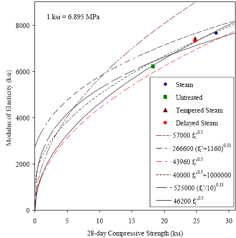 Figure 146. Equation. Approximation for UHPC modulus of elasticity (in psi). All of these equations have a similar form, some differing only by the scalar factor. The UHPC modulus of elasticity results were reevaluated to determine what type of relationship and what scalar factor would provide the best fit to the observed results. It was determined that the form of the ACI 318 equation accurately represented the shape of the UHPC relationship and only a modification of the scalar factor was required. The result of this analysis is the equation shown in figure 146 which has an R-squared value of 0.967 for the UHPC experimental results with compressive strengths above 25 MPa (3.6 ksi). This relationship is also shown in figures 145 and 147. Figure 147 presents the most relevant equations along with the data that was used in this analysis. The figure also included the data from compressive strengths below 25 MPa (3.6 ksi) which was excluded from this analysis. The figure shows that the equation in figure 146 is applicable to UHPC over a wide range of strengths, not just to the final strength values between 124 and 193 MPa (18 and 28 ksi). Therefore, this equation is considered applicable over the compressive strength range of 28 to 193 MPa (4 to 28 ksi). Note that the ACI 363 and Ma equations displayed lower R-squared values (0.957 and 0.881, respectively), and they both overestimate the observed modulus of elasticity results at a large margin at lower compressive strengths. Figure 147. Graph. Modulus of elasticity as a function of compressive strength. 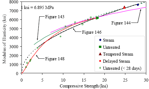
The equation in figure 146 does not accurately estimate the modulus of elasticity for UHPC with a compressive strength in the 7 to 21 MPa (1 to 3 ksi) range. The equation can overestimate the modulus of elasticity by as much as 50 percent. To rectify this lapse in the applicability of the equation, a more sophisticated equation was used to approximate the untreated curing regime data shown in figure 147. A best-fit regression analysis was applied to these data to determine a function that accurately represented the behavior. The simplest function to meet the requirements was the Log Normal function as presented in figure 148. In this equation, fc' is the compressive strength of the concrete at a particular age and E is the corresponding modulus of elasticity, both in psi. This equation can be used to approximate the modulus of elasticity for compressive strengths as large as 131 MPa (19 ksi). Figure 148. Equation. UHPC modulus of elasticity approximation (in psi) for compressive strengths up to 131 MPa (19 ksi). 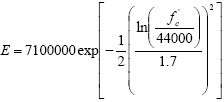 4.9 COMPRESSIVE STRESS-STRAIN BEHAVIOR OF UHPCThe compressive stress-strain behavior of UHPC has been discussed extensively in this report, including the material property characterization results presented in section 3.3 and a further analysis of those results presented in section 4.8. The current section presents an analysis wherein an equation is determined that represents the ascending branch of the compressive stress-strain response for each of the four curing regimes. This analysis is based on the experimental results presented in section 3.3.3. The compressive stress-strain responses of different concretes vary because concrete is a heterogeneous material without standardized mix designs. Many researchers have presented analytical approximations for the ascending branch of the compressive stress-strain behavior, all of which have been based on specific sets of experimental data. However, this body of research has resulted in minimal consensus on the equation’s formulation or results.(20) From an experimental standpoint, gathering consistent, accurate data from the full range of compressive behavior response is very difficult. This fact is primarily due to the increasingly nonlinear behaviors that concrete tends to exhibit as the strain at the compressive strength is reached and surpassed. Even if the descending branch of the behavior is ignored as the compressive strength is approached, the observed straining behavior of the concrete becomes very dependent on the experimental loading and strain measurement techniques that have been used. The preceding discussion leads to the conclusion that any strength values and strain values from earlier in the concrete response are likely more accurate than strain values from later in the concrete response. The concrete compressive strength, fc', and the concrete modulus of elasticity, E, can both be considered to be relatively accurate based on experimental results. However, the concrete strain at the compressive strength and the associated secant modulus are both based on strain measurements that are more difficult to capture accurately and are thus less accurately known. This fact points to a weakness of many other models of concrete compressive stress-strain behavior, because they are based on an accurate knowledge of the compressive strain at the peak strength. Recall from section 3.3 that a number of specific parameters were quantified within the compressive stress-strain responses of the UHPC. Intermediate stress and strain level benchmarks were identified in addition to the standard strength and stiffness measures. These benchmarks were defined by the decrease in observed stress compared with a theoretical linear elastic response at a particular strain. Average results for the 1, 3, and 5 percent decrease levels were presented in table 11. For this analysis, additional benchmarks were defined at the 10 percent decrease level and at the cessation of the continuous, steady increase in stress-strain response. Figure 149 illustrates the stress decrease factor compared with the linear elastic behavior, α, on a sample untreated UHPC compressive stress-strain curve. Sample actual stress, fc, and strain, εc, values are shown along with the stress and strain differences from the linear elastic response. Figure 149. Graph. Compressive stress-strain behavior compared with linear elastic response. 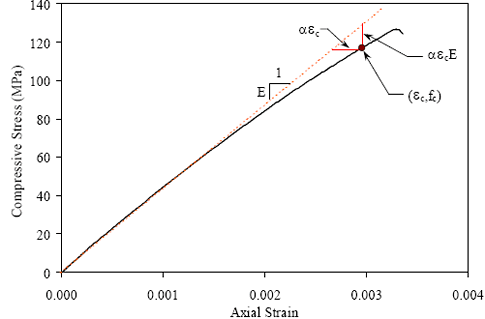
1 MPa = 0.145 ksi These benchmarks were used to define the behavior of each compressive specimen. The results were then normalized based on the compressive strength and modulus of each specimen. Note that although the compressive stress normalization is based on the experimentally obtained compressive strength, the strain normalization is based on the theoretical linear elastic strain at the compressive strength. This normalization technique minimizes the inaccuracies discussed above by avoiding the use of the actual strain at the compressive strength. Finally, the results from each curing regime were compiled into individual data sets. Figure 150 presents the normalized stress-strain response benchmark data points for the steam-treated UHPC cylinders discussed in section 3.3. This figure shows the general shape that the approximation must match to accurately represent the UHPC behavior. However, it does not allow for easy differentiation between potential curves that fit the data. A more accurate representation of the overall behavior can be obtained by focusing on the deviation of the actual behavior of the concrete compared with the theoretical linear elastic response. Figure 151 presents the same benchmarks in terms of the decrease from the linear elastic response compared with the normalized strain. This presentation highlights the behaviors that must be captured in the model. Figure 150. Graph. Normalized compressive stress-strain results for steam-treated UHPC. 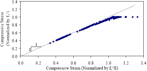
Figures similar to figure 151 were created for the other three curing regimes as well. In all cases, the figures indicate that the UHPC remains close to the theoretical linear elastic response through much of its behavior. Approximation curves were fit to each of these data sets. The simplest equation that fits the data moderately well was an exponential function with two constants as provided in figure 152. These constants, a and b, help fit the equation to the data, and their values for each curing regime are provided in table 38. The approximation curve for the steam-treated UHPC is shown in figure 151. The analysis discussed above leads to a simple means of defining the ascending branch of the compressive stress-strain response of UHPC. Figure 153 presents the equation for the standard linear elastic relationship between stress and strain with the inclusion of a modifying factor. This factor, specifically (1-α), determines the extent to which the actual curve deviates from the linear elastic response. Recall that α is defined by the equation in figure 152. Dividing the equation in figure 153 by the compressive strength normalizes the equation and allows for the direct inclusion of the equation in figure 152 and therefore a single equation defining the normalized compressive stress in terms of the normalized compressive strain. Recall that this equation was derived to be applicable only for the ascending branch of the curve. These relationships were used to create general stress-strain responses for the four curing regimes. These responses were based on the compressive strength and modulus of elasticity results presented in chapter 3. The curves are shown in figure 154. Figure 151. Graph. Deviation from linear elastic compressive behavior for steam-treated UHPC. 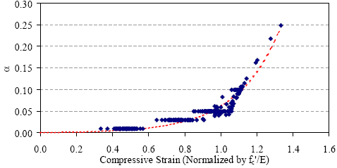 Figure 152. Equation. Deviation of compressive stress-strain response from linear elastic behavior.
Figure 153. Equation. Compressive stress-strain behavior defined as a function of the deviation from linear elastic behavior. Figure 154. Graph. Compressive stress-strain response approximations. 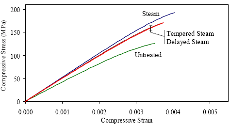
1 MPa = 145 psi
|