U.S. Department of Transportation
Federal Highway Administration
1200 New Jersey Avenue, SE
Washington, DC 20590
202-366-4000
Federal Highway Administration Research and Technology
Coordinating, Developing, and Delivering Highway Transportation Innovations
 |
| This report is an archived publication and may contain dated technical, contact, and link information |
|
Publication Number: FHWA-RD-99-194
Date: June 2000 |
|||||||||||||||||||||||||||||||||||||||||||||||||||||||||||||||||||||||||||||||||||||||||||||||||||||||||||||||||||||||||||||||||||||||||||||
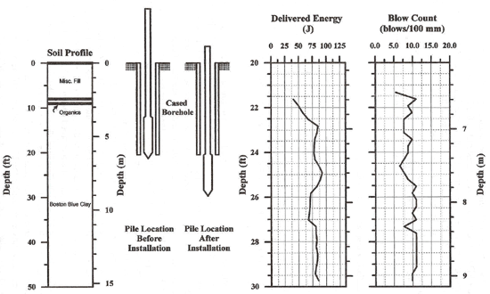
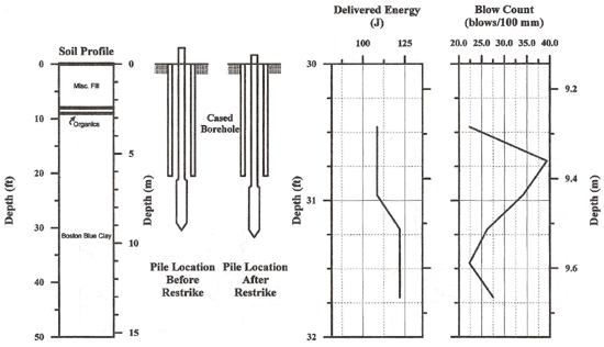
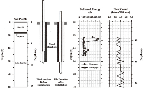
Development and Field Testing of Multiple Deployment Model Pile (MDMP)CHAPTER 6. NEWBURY SITE TEST RESULTS (continued)6.6 Dynamic Measurements6.6.1 Driving System and Dynamic MeasurementsThe top of the drill rod string was instrumented (Surface Measurement) with strain gauges and accelerometers as part of a dynamic measurement system manufactured by Pile Dynamics, Inc. of Cleveland Ohio. A Pile-Driving Analyzer (PDA) (model PAK) monitored the gauges during the MDMP installation and a subsequent restrike following the completion of the pore pressure dissipation. In addition, the internal load cells and accelerometers (at the top and middle load cell locations) were monitored with additional PDA provided by Mr. Carl Ealy, a Geotechnical Research Engineer from FHWA. The force wave was measured using the MDMP internal load cells mounted in the model pile and designed for static load application. Reusable gauges manufactured by Pile Dynamics, Inc., specifically designed for dynamic applications, were bolted to the drill rods to monitor the impact force at the pile top. The acceleration of the pile was recorded by three accelerometers that were mounted internally inside each load cell and externally with up to four accelerometers bolted on the drill rods. Of the three accelerometers inside the MDMP, two were of the piezoelectric type and were mounted inside the top and bottom load cells, while the accelerometer mounted inside the middle load cell was a piezoresistive type. The driving system consisted of a 0.623-kN (140-lb) safety hammer normally used for Standard Penetration Tests (SPT). The operator of the drill rig controlled the hammer drop by visual inspection. During the installation of the MDMP Test NB2, the stroke of the hammer was initially limited to 0.152 m (6 in) to ensure that dynamic stresses would not harm the instruments inside the MDMP. Since all instrumentation continued to record data within the assigned limits, the stroke was subsequently increased to 0.305 m (12 in) and then to 0.457 m (18 in). The compressive stresses, recorded by the PDA during the driving sequences, did not exceed 90% of the yield strength (0.9fy) of steel in order to avoid overstressing the pile. The number of blows required to drive the pile a predetermined amount was visually observed and recorded during driving. The force and acceleration data were recorded with the two PDAs at a frequency of 20,000 Hz (one test was at 5,000 Hz). The recorded blows from each PDA were synchronized by using the time stamp for each PDA. Several indiscriminate blows were recorded by the internal load cells and accelerometers, possibly caused by the vibrations that triggered the PDA. The initial trigger threshold of the PDA was a velocity of 0.25 m/sec. After the first blow, the trigger level became 20% of the previous peak (PDA, 1995). Since low velocities (on the order of 1.5 m/sec) were recorded in the pile, 20% of the peak velocity was relatively small, thus making the PDA trigger sensitive to vibrations or early reflections from changes in impedance that might cause the PDA to continuously trigger. Appendix I presents the driving logs and synchronized records from all the load cells during pile penetration. The maximum force and velocity records are included to indicate the quality and consistency of the measurements. 6.6.2 Installation During Model Pile Test NB2(1) Assembly and Recorded Data.. The assembled pile consisted of the 2.87-m (9.4-ft) instrumented section with four 1.52-m (5-ft) and two 0.61-m (2-ft) drill rod sections. The total length of the pile during installation was 10.2 m (33.4 ft). The gauges were located 0.3 m (1 ft), 8.0 m (26.3 ft), and 8.7 m (28.7 ft) from the top of the assembled pile. The pile was placed into a 6.25-m (20.5-ft) cased borehole and penetrated 0.25 m (0.82 ft) due to self-weight. Figure 71 shows the relative position of the MDMP before and after driving. During installation, 254 blows were recorded with the gauges located at the pile top (surface measurements) and 268 blows were recorded by the PDA monitoring the internal instruments. To match the data from both PDAs, the time stamps were compared at the start of driving, at the break in driving, and at the end of driving. The difference between the time stamps of each PDA was 279 s. The pile was driven 2.57 m (8.42 ft) and the number of blows per 91.4 mm (3.6 in) of penetration was recorded. There were 23 blows that were not accounted for due to error in counting over a penetration of 183 mm (0.6 ft). At the point when the error occurred, the previous and following blow counts were both 10 blows per 91.4 mm (3.6 in). Adding two additional 91.4-mm (3.6-in) increments accounts for 20 of the missing blows if the assumed blow count was 10 blows per 91.4 mm (3.6 in). With the two additional increments, the total penetration as recorded with the blow count is 2.65 m (8.7 ft), or 91.4 mm (3.6 in) more than actually penetrated. This discrepancy may be attributed to inaccurate marking of the rods by the driller or incorrect blow counts. In addition to the outline of the pile installation and observed driving resistance, Figure 71 contains the measured energy at the top of the pile during the driving (surface measurement). The measured energy allows better assessment of the observed blow count, with a possible use of a simplified direct relationship between the energy level and the blow count. For example, an increase in blow count under the same energy suggests an increase in capacity; however, double the blow count for half the delivered energy would correspond to no change in the resistance. The analyses of the pile capacity based on the dynamic measurements will be presented in Chapter 7.
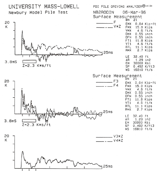
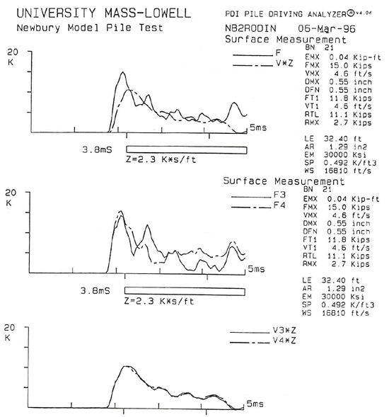
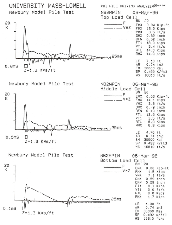
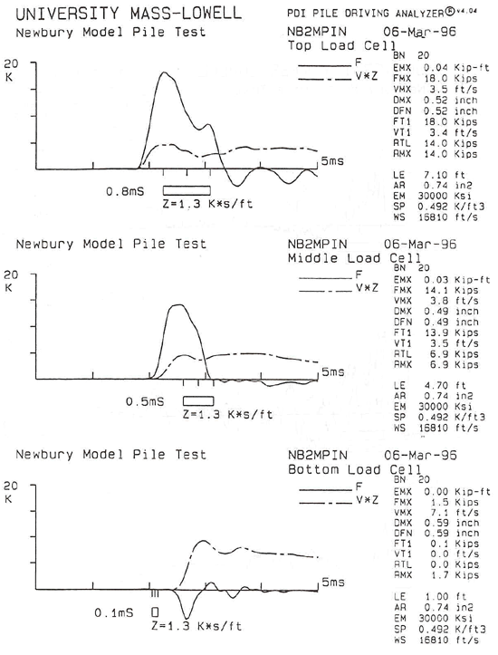
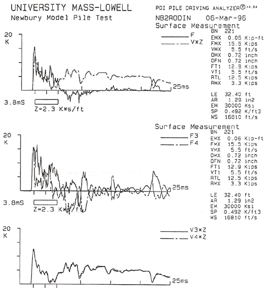
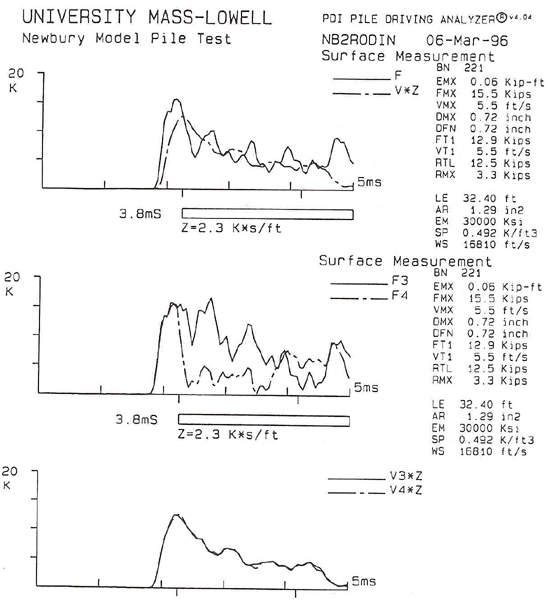
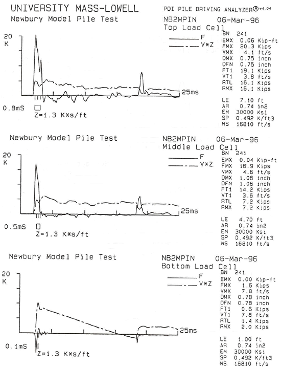
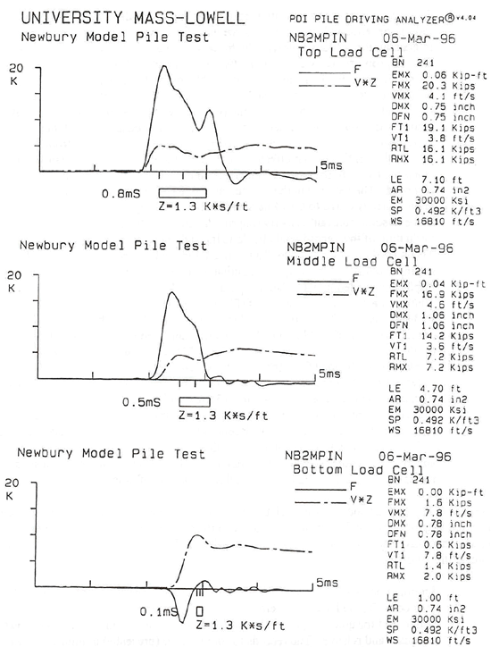
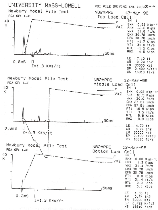
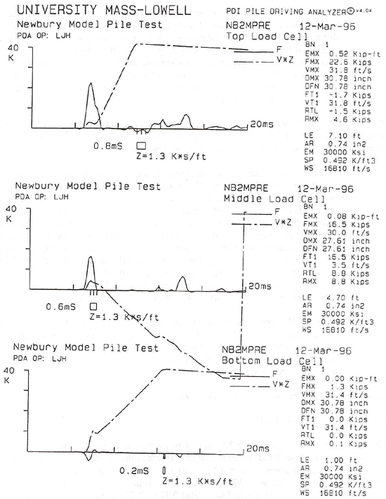
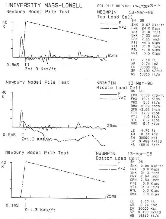
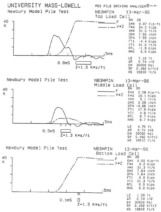
(2) Typical Dynamic Measurements. Typical dynamic measurement data obtained via the PDA along the MDMP during driving of NB2 are shown in Figures 72 and 73. Figures 72 and 73 present the force and velocity signals recorded at the top of the drill rods (denoted as surface measurement) and the internal load cells inside the pile above and below the friction sleeve (denoted as top load cell and middle load cell) and at the pile tip (denoted as bottom load cell) for two blows. Note that the data related to blow 21 in Figures 72a and b corresponded to the same impact denoted as blow 20 in Figures 72c and d. In the same way the data related to blow 221 in Figures 73a and b correspond to the same blow denoted as blow 241 in Figures 73c and d. The different notations are a result of the use of two different acquisition (PDA) systems as previously described (section 4.3). Blows 21/20 and 221/241 were recorded at penetration depths of approximately 6.74/0.183 m (22.1/0.6 ft) and 8.69/2.44 m (28.5/8.0 ft) as related to the ground surface and the bottom of the cased borehole, respectively. The data in Figures 72a and 73a were related to the surface measurements for a time period of 25 ms, while Figures 72b and 73b depict the same data over a 5-ms period detailing the impact wave and its reflections during the travel time down to the tip and back. The data in Figures 72a and b and 73a and b indicated the following: 1. Surface
Force - The force at the top of the rods seemed to undergo sharp
fluctuations. Examining the individual
force records led to the conclusion that F3 was the main contributor to the
variations, while the force records of F4 contained smaller variations. Three possible reasons could be connected to
these fluctuations: (1) the vibrations of the strain transducers themselves -
the small diameter of the drill rod (in comparison with a full-scale pile) made
the attachment of the force transducers difficult and, as a result, the
transducers can vibrate during driving; (2) the rods were made of sections of
mechanical tubing with screw sections welded to each end - the large increase
in the impedance of the rods at each connection resulted in a force reflection
that was recorded as an increased force at the surface measurement; and (3) the
differences between F3 and F4 suggested the existence of an uneven impact at
the pile top - if the transducers were mounted close to the impact (in this
case, 0.305 m below the top drill rods and approximately 1.25 m from the
impact), then the records would reflect the uneven stress distribution in the
pile. A better understanding of the
source of the presented records could be obtained through the examination of
the surface force records obtained during the MDMP driving of NB3. During this driving, two sets of surface
gauges were attached to the drill rods, allowing a better assessment of the fluctuation source in the force measurements. The data and relevant discussion are presented in section 6.6.4 and Figures 77a through f.
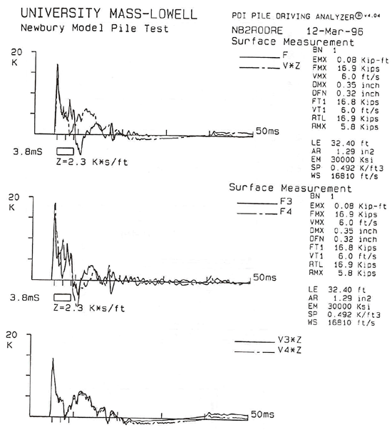
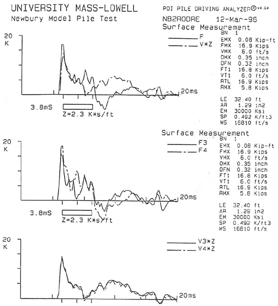
2. Surface Velocity - The velocity record at the top of the drill rods was multiplied by the rod's impedance and presented in force units for comparison to force measurements. In general, the velocity followed the force signal due to the input hammer blow. The ratio of proportionality between the two peaks (velocity*impedance/force) ranged from 0.76 to 0.89. This ratio was reasonable under the anticipated uneven stress distribution resulting from the SPT hammer blow. The smoother shape of the velocity curve and the nice match between the two independent records suggested that the record was valid as the acceleration record would not be affected by the aforementioned factors affecting the force record. The only factor from those previously mentioned that affected the velocity record was the impedance variations along the rods. In the case of an increase in impedance, a decrease in the velocity was recorded. The increase in the velocity at about 7 ms to an elevated level of approximately 0.610 to 0.914 m/sec (2 to 3 ft/sec) suggested that the pile continued to move at some constant velocity (approximately) over a lengthy period of time. The evaluation of this record could be done through integration of the velocity over time. This record provided the pile displacement and could be compared to the observed driving records. Moreover, with continuous motion of easy driving, the maximum displacement (denoted as DMX) should be equal to the final displacement (denoted DFN). The record for blow 21/20 (Figure 72) indicated that, indeed, DMX=DFN=13.97 mm (0.55 in). This compared well with the observed displacement of eight blows per 91.44 mm (3.6 in), which translated to an average of 11.43 mm (0.45 in) per blow. This is not so for blow 221/241 (Figure 73), where the displacement obtained from the velocity record (DMX=DFN=18.3 mm (0.72 in)) differed from the penetration resistance of 10 blows per 91.44 mm (3.6 in), which translated to an average of 9.14 mm (0.36 in) per blow. It should be emphasized that for acceleration records over a long period, double integration (in order to obtain displacement) is prone to increasing inaccuracy. Small DC voltage in the acceleration record will be integrated to a triangular-shaped velocity added to the actual record. Integration of this component will result in a second order increase at the displacement record, all as a function of time. The data in Figures 72c and 73c were related to the internal measurements for a time period of 25 ms, while Figures 72d and 73d depict the same data over a 5-ms period to show the details of the impact wave traveling down through the pile. The data in Figures 72c and d and 73c and d indicate the following: 1. Internal Forces - The internal forces were recorded using the existing built-in large load cells. These load cells were designed for measuring static loads and were not configured for quick response. In spite of this fact, the obtained records seemed to be adequate and reliable. The records for blow 21/20 (presented in Figure 72c and d) suggested that the wave arrived to the top load cell as about 1.2 times the magnitude of the wave recorded at the surface and was of a similar shape. The ratio between the surface load cell and the top load cell force measurement for blow 221/241 was 1.3. Both records reflected the influence of the impedance increase when the rods were connected to the instrumented pile. Evaluation of this increase over the penetration record is presented in Chapter 7, where it is shown to match the expected analysis. The peak wave passing through the middle load cell was reduced by about 17.3 and 15.1 kN (3.9 and 3.4 kips) for blows 21/20 and 221/241, respectively. This reduction was equal to the friction force acting on the sleeve and will be discussed further in Chapter 7. The discontinuity of the internal force records was a result of the MDMP slip joint. The impact was transferred to the lower section, which separated because it was incapable of transferring the reflected wave coming from the tip. The records referring to the bottom load cell related to the gauges installed in the segment about 1.2 m (3.8 ft) below the slip joint and about 178 mm (7 in) from the tip of the pile. Both records (referring to blows 21 and 221 in Figure 72 and 73) showed consistent behavior. A negative force was recorded with a downward velocity. The impact at the slip joint sent a compressive wave down the lower section of the pile. This compressive stress, under easy driving conditions, should be reflected as a tensile stress upwards. Therefore, the expected records should have consisted of compressive and tensile waves, differing from the presented records. It is unclear as to why the recorded wave shape is in its present form. One possibility is an uncommon electronic problem known to exist with the electrical strain gauges system (Rausche, 1997). 2. Internal Velocities - Overall, the acceleration records at all locations seemed to provide consistent and reliable velocity signals. The data in Figures 72a and b and 73a and b suggested that both accelerometers mounted at the surface worked well throughout the driving, independently providing a velocity record that matched very well with each other. The overall good performance of the accelerometers suggested that: (1) the installation of only one accelerometer at each internal load cell was justified, and (2) the single velocity signals at each elevation within the pile were reliable. The constant velocity throughout the record suggested a continuous pile movement at a steady velocity. The velocity records for blow 21 (Figure 72c and d) showed that the top and middle accelerometer records translated to 13.2 and 12.4 mm (0.52 and 0.49 in) of displacement, respectively. These measurements compared well to the 14.0-mm (0.55-in) movement recorded at the surface and the average of 11.4 mm (0.45 in) per blow during the driving. The velocity records for blow 221 (Figure 73c and d) showed that the top and middle accelerometer records translated to 19.1 and 26.9 mm (0.75 and 1.06 in) of displacement, respectively. These measurements compared well with the 18.3-mm (0.72-in) movement recorded at the surface, but did not compare well with the average of 9.1 mm (0.36 in) per blow during driving. The displacement of the tip element for blows 21 and 221 was 15.0 and 19.8 mm (0.59 and 0.78 in), which seemed reasonable considering the fact that the lower segment could separate from that above. The velocity record for the bottom segment indicated deceleration at a constant rate, resulting in a constant reduction in the velocity record. This seemed to be the result of the lower segment separating at the slip joint and traveling against the surrounding soil. 6.6.3 MDMP Restrike During Model Pile Test NB2(1) Assembly and Recorded Data. The MDMP installation as described in the previous section was conducted on March 6, 1996 at 6 p.m. Following the completion of the pore pressure dissipation and the static load tests (including the cyclic loading (see section 6.5)), a dynamic restrike was conducted on March 12, 1996 at 2:50 p.m. The pile assembly and gauge locations were identical to that of the initial installation as outlined in the previous section. Figure 74 shows the relative position of the MDMP before and after the restrike. During the restrike, 120 blows were recorded by the surface gauges and 119 blows were recorded by the PDA monitoring the internal instruments. The difference between the time stamps of the two PDAs was 283 s. The pile was driven 0.406 m (1.3 ft). The number of blows required to penetrate each 76.2 mm (3 in) were recorded during the restrike. A total of 117 blows were recorded as part of the manual blow counting procedure, 3 less than the number recorded by the PDA. The total penetration during the restrike was solely determined from the pile-driving log. In addition to the outline of the pile installation and observed driving resistance, Figure 74 contains the measured energy at the top of the pile during the driving (surface measurement). The measured energy allowed a better assessment of the observed blow count with the possible use of a simplified direct relationship between the energy level and the blow count. The analyses of the pile capacity based on the dynamic measurements will be presented in Chapter 7. (2) Typical Dynamic Measurements. Typical dynamic measurement data obtained via the PDA along the MDMP during the restrike of NB2 are shown in Figure 75. Figure 75 presents the force and velocity signals recorded at the top of the drill rods (denoted as surface measurement) and the internal load cells inside the pile above and below the friction sleeve (denoted as top load cell and middle load cell) and at the pile tip (denoted as bottom load cell) for blow 1. Blow 1 was also analyzed using CAPWAP analysis and the results are included in Chapter 7. The data in Figure 75a were related to the surface measurements for a time period of 50 ms while Figure 75b depicts the same data over a 20 ms period detailing the impact wave and its reflections during travel time down to the tip and back. The energy measured in blow 1 was about double than that recorded during the initial driving of NB2 and about 33% higher than that at the end of driving. The data in Figure 75a and b indicated the following: 1. Surface Force - Similar to the force recorded during installation, at approximately 2.5 ms after the peak force was recorded, an increase in the force was measured. This positive increase was associated with the reflection of the traveling wave from the rod/pile connection at a distance of 7.01 m (23 ft) from the surface measurement.
2. Surface Velocity - The velocity record at the top of the drill rods behaved much the same as during the installation. Unlike the easy driving encountered during initial driving, the velocity record did not increase to an elevated level. DMX (maximum pile top displacement) was 8.9 mm (0.35 in), while DFN (final pile top displacement) was 8.1 mm (0.32 in) compared to the average set of 4.5 mm (0.176 in) per blow. This could be the result of the difference in the pile behavior between each individual blow and the average set for a number of blows as shown in Figure 74 and detailed in the driving log in Appendix I. The data in Figure 75c were related to the internal measurements for a time period of 50 ms, while Figure 75d depicts the same data over a 20-ms period detailing the impact wave traveling down through the pile. The data in Figure 75c and d indicated the following:
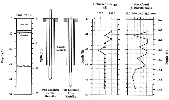
6.6.4 Installation During Model Pile Test NB3(1) Assembly and Recorded Data. The assembled pile consisted of the 2.87-m (9.4-ft) instrumented section with seven 1.52-m (5-ft) and two 0.61-m (2-ft) drill rod sections. The total length of the pile during installation was 14.8 m (48.4 ft). The gauges were located 0.3 m (1 ft), 0.91 m (3 ft), 12.6 m (41.3 ft), and 13.3 m (43.7 ft) from the top of the assembled pile. The pile was placed in a 9.3-m (30.5-ft) cased borehole and held in place after it had penetrated 0.37 m (1.23 ft) under its own weight (including the weight of the drill rods). The pile would have continued to penetrate if not physically held in place for approximately 1.5 h. When disconnected from the drill rig following this period, the pile did not appear to penetrate any farther. Figure 76 shows the relative position of the pile before and after installation.
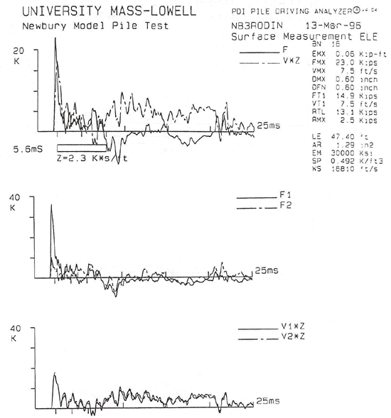
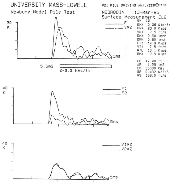
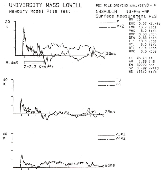
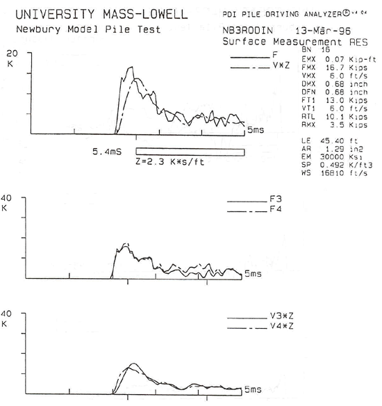
The dynamic records for the first 30 blows were recorded with the gauges attached to the pile top (surface measurements). Only the first 30 blows were recorded by the PDA due to limited storage space in that particular PDA (860 blows in the buffer) and the oversight of leaving the data recorded earlier during MDMP test NB2. The surface measurements included two sets of gauges attached to the drill rods, each with a different type of accelerometer - piezoelectric and piezoresistive. The PDA monitoring the internal instruments recorded 100 blows. The difference between the time stamps of the two PDAs was 283 s. The pile was driven 2.54 m (8.33 ft). Ninety blows were recorded for a total penetration of 2.44 m (8.0 ft). Discounting the random blows recorded by the PDA measuring the internal gauges, the blow count appeared to be reasonable. The error in the total penetration length was 101.6 mm (4 in). This error could be attributed to the incorrect marking of the 76.2-mm (3-in) increments on the drill rods or a missed increment during driving. In addition to outlining the pile installation and the observed driving resistance, Figure 76 contains the measured energy at the top of the pile during the driving (surface measurement). The measured energy allowed better assessment of the observed blow count, with the possible use of a simplified direct relationship between the energy level and the blow count. The analyses of the pile capacity based on the dynamic measurements will be presented in Chapter 7. (2) Typical Dynamic Measurements. Typical dynamic measurement data obtained via the PDA along the MDMP during driving of NB3 are shown in Figure 77. Figure 77 presents the force and velocity signals recorded at two places at the top of the drill rods (denoted as surface measurement ELE and surface measurement RES) and the internal load cells inside the pile above and below the friction sleeve (denoted as top load cell and middle load cell) and at the pile tip (denoted as bottom load cell) for one blow. Note that the data related to blow 16 in Figures 72a through d corresponded to the same blow denoted as blow 26 in Figures 72e and f. Blow 16/26 corresponded to a penetration depth of approximately 10.13/0.83 m (33.23/2.73 ft) as related to the ground surface and bottom of the cased borehole, respectively. The data in Figures 77a and c were related to the surface measurements for a time period of 25 ms, while Figures 77b and d depict the same data over a 5-ms period detailing the impact wave and its reflections during the travel time down to the tip and back. The data in Figures 77a through d indicated the following: 1. Surface Force - During the installation of NB3, two sets of force transducers and accelerometers (a total of four force transducers and four accelerometers) were mounted at the top of the pile. The records denoted as F1 and F2 referred to the force transducers mounted 0.3048 m (1 ft) below the top of the drill rods (approximately 1.25 m from the impact) in an arrangement similar to the one used for the NB2 installation. The records for these transducers, as shown in Figures 77a and b, were very similar in nature to those obtained in MDMP test NB2 (see Figures 72a and b). The records denoted as F3 and F4, shown in Figure 77c and d, referred to measurements 0.91 m (3 ft) below the top of the drill rods (approximately 1.86 m below the impact), meaning 0.610 m (2 ft) below F1 and F2.Although the average recorded force indicated some fluctuation (see force and velocity records combined), the individual records suggested that both F3 and F4 measured a similar record. As a result, it can be concluded that due to changes in impedance in the rods, compressive force reflections were measured at the pile top. However, due to unevenly distributed stresses during impact, gauges that were mounted only 0.3048 m (1 ft) below the top of the rods suffered from extreme variations and resulted in highly fluctuated forces. Although 0.305 m (1 ft) below the top of the rods seemed to be a more than safe distance (compared to full-scale pile operation in which the gauges are mounted three pile diameters below the impact), the dynamic measurements on a small-scale pile were difficult and required increased distance to ensure quality data that were not affected by uneven impacts.
2. Surface Velocity - The velocity records at the top of the drill rods appeared to be of the same basic shape as those observed in the driving of test NB2 (see section 6.6.2). The increased velocity at about 8 ms, to an elevated level of approximately 0.610 to 0.914 m/sec (2 to 3 ft/sec), suggested that the pile continued to move at some constant velocity (approximately) over a lengthy period of time. As shown before, during easy driving, the record for blow 16 (Figure 77e and f) indicated that, indeed, DMX=DFN=15.24 mm (0.60 in). This was in comparison with the observed displacement of three blows per 76.2 mm (3.0 in), which translated to an average of 25.4 mm (1.0 in) per blow. The data in Figure 77e were related to the internal measurements for a time period of 25 ms, while Figure 77f depicts the same data over a 5-ms period detailing the impact wave and its reflections during the travel time down to the tip and back. The data in Figures 77e and f indicated the following: 1. Internal Forces - The internal forces were recorded using the existing built-in large load cells. The records for blow 16 (presented in Figures 77e and f) suggested that the wave arriving at the top load cell was about 1.04 times the magnitude of the wave recorded at the surface with the upper instrumentation as shown in Figures 77a and b for the records for F1 and F2. The ratio between the surface load cell and the top load cell for blow 16 was 1.44 times the magnitude of the wave recorded at the surface with the lower instrumentation as shown in Figures 77c and d for the records for F3 and F4. Both records were affected by the impedance increase at the connection of the drilling rods and the instrumented pile. An evaluation of this increase over the penetration record is presented in Chapter 7, where it is shown to match the expected analysis. The peak wave passing through the middle load cell was reduced by about 21.8 kN (4.9 kips). This reduction was equal to the dynamic friction force acting on the sleeve and will be discussed further
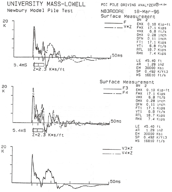
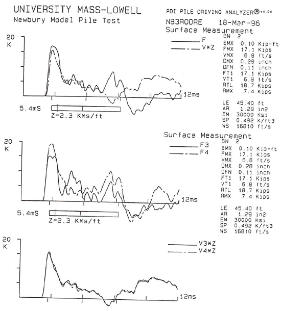
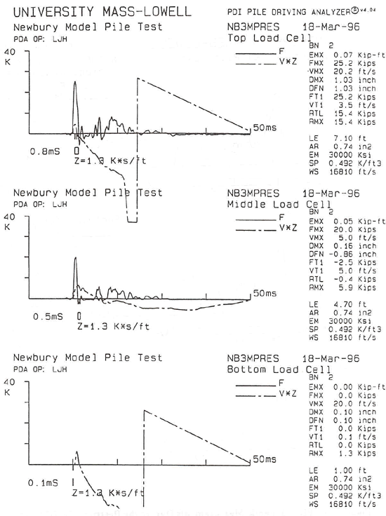
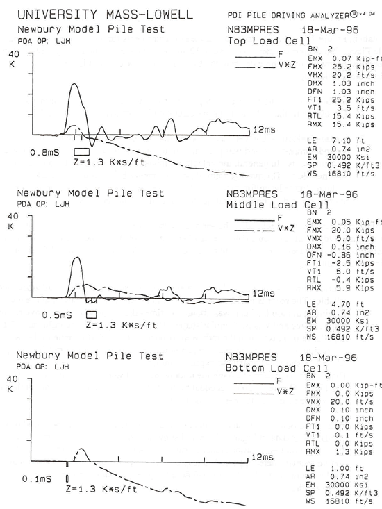
in Chapter 7. The discontinuity of the internal records was a result of the MDMP slip joint. The impact was transferred to the lower section that separated; it was incapable of transferring the reflected wave coming from the tip. 2. Internal Velocities - The accelerometer records were questionable during the initial installation of NB3. The data in Figures 77e and f suggested that the accelerometers mounted at the top and bottom locations reached saturation and thus were not reliable. The middle accelerometer appeared to respond properly, but the large negative final displacement of DFN = -93.0 mm (-3.66 in) suggested that its reliability beyond about 2.5 ms (see Figure 77e) was questionable, most likely due to drift at the DC level. 6.6.5 Restrike During Model Pile Test NB3(1) Assembly and Recorded Data. The assembled pile consisted of the 2.87-m (9.4-ft) instrumented section with seven 1.52-m (5-ft) and one 0.61-m (2-ft) drill rod sections. The total length of the pile during installation was 14.1 m (46.4 ft). The gauges were located 0.3 m (1 ft), 12.0 m (39.3 ft), and 12.7 m (41.7 ft) from the top of the assembled pile. Following the completion of the dissipation process and static load tests (including the cyclic loading (see section 6.5)), a dynamic restrike was conducted on March 18, 1996 at 3:38 p.m. Figure 78 shows the relative position of the pile before and after the restrike. During the restrike, 359 blows were recorded by the surface gauges and 351 blows were recorded by the PDA monitoring the internal instruments. The difference between the time stamps of the two PDAs was 289 s. The pile was driven 1.22 m (4.0 ft). The number of blows needed to penetrate 76.2 mm (3 in) were recorded during the restrike. A total of 361 blows were recorded as part of the blow-counting procedure, 2 more than recorded by the PDA. The total penetration during the restrike was determined solely from the pile-driving log. In addition to the outline of the pile installation and observed driving resistance, Figure 78 contains the measured energy at the top of the pile during the driving (surface measurement). The measured energy allowed better assessment of the observed blow count with the possible use of a simplified direct relationship between the energy level and the blow count. The analyses of the pile capacity based on the dynamic measurements will be presented in Chapter 7. (2) Typical Dynamic Measurements. Typical dynamic measurement data obtained via the PDA along the MDMP during restrike of NB3 are shown in Figure 79. Figure 79 presents the force and velocity signals recorded at the top of the drill rods (denoted as surface measurement) and the internal load cells inside the pile above and below the friction sleeve (denoted as top load cell and middle load cell) and at the pile tip (denoted as bottom load cell) for blow 2. Blow 2 was analyzed using CAPWAP analysis and the results are presented in Chapter 7.
The data in Figure 79a were related to the surface measurements for a time period of 50 ms, while Figure 79b depicts the same data over a 12-ms period detailing the impact wave and its reflections during the travel time down to the tip and back. The data in Figures 79a and b indicated the following:
The data in Figure 79c were related to the surface measurements for a time period of 50 ms, while Figure 79d depicts the same data over a 12-ms period, detailing the impact wave and its reflections during the travel time down to the tip and back. The data in Figures 79c and d indicated the following:
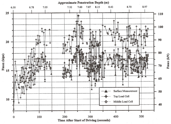
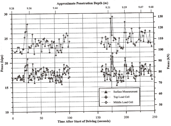
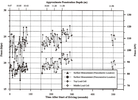
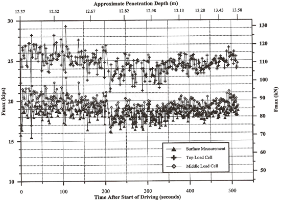
6.6.6 Force MeasurementsThe two surface force transducers bolted to the drill rods at 180° across from each other recorded different forces for the same blow. Since the gauges were on opposite sides of the pile, the cause of the different force measurements was eccentric impact, i.e., the hammer was not striking the guide rod evenly at a plane perpendicular to the direction of the traveling wave. The force signals inside the MDMP were measured using a single axial load cell a long distance from the impact. As a result, the internal load cells were not capable of identifying uneven stress distribution in the pile wall. The safety hammer was not inspected to confirm the cause of the uneven force measurements. The force measurements for gauges bolted to the drill rods were averaged together to yield an average force that was used for all subsequent analyses. Figures 72, 73, 75, 77, and 79 all indicate the existence of uneven contact stresses during the impact. Figures 80 through 83 present the maximum (peak) forces recorded for each blow at three gauge positions: surface measurement, and top and middle load cell locations. In general, the peak forces recorded at the surface and middle load cell locations were of the same magnitude, while higher forces were measured at the top load cell location. An important observation from these figures was that the gauges in the MDMP recorded consistent data. Table 28 presents the average peak forces recorded at each location during each stage of driving. The standard deviation decreased after the first test because during the NB2 installation, the appropriate stroke was investigated and was maintained in subsequent driving. Initially, a 0.152-m (6-in) stroke was examined and subsequently increased to 0.305 m (12 in) and then to 0.457 m (18 in). The remaining tests were conducted with a 0.457-m (18-in) stroke. Table 28. Average Peak Forces Measured at Three Locations in the MDMP.
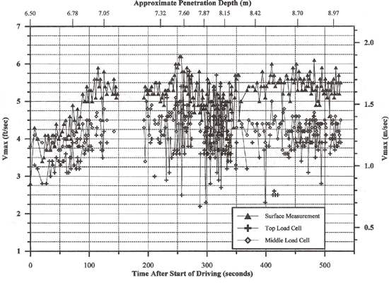
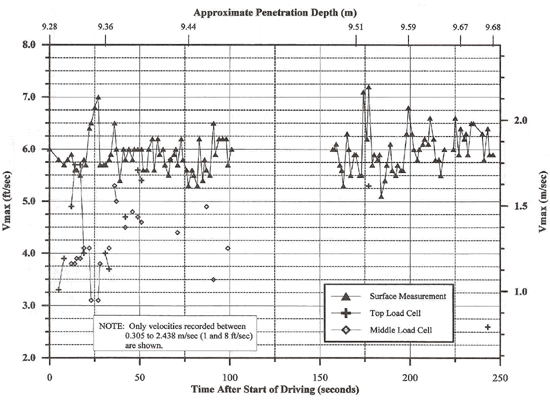
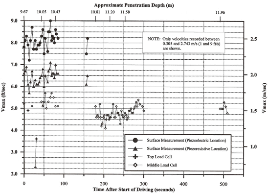
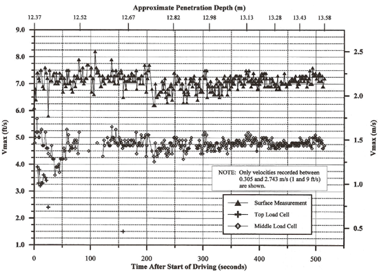
6.6.7 Velocity MeasurementsThe average velocity measured during each of the tests are shown in Table 29. Figures 84 through 87 show that the measurements at the surface location were consistent and yielded average proportionality ratios of 0.76, 0.78, 0.79, and 0.89 for NB2 installation, NB2 restrike, NB3 installation (piezoresistive gauge), and NB3 restrike, respectively. The velocity records from the top load cell location were inconsistent and many times the signal appeared to be saturated. This indicated that the connection of the accelerometer to its mount and/or the mount to the load cell wall was not secure or possibly that the accelerometer was broken. Based on the fact that the accelerometer did record sporadic data, the connection of the accelerometer to the pile seemed to be the reason for the difficulties. Similar irregularities appeared in the velocity measurements at the middle load cell location, but were far less frequent. The average value presented in Table 29 for the middle load cell location only included velocities between 0.305 and 2.44 m/s (1 and 9 ft/s).
Table 29. Average Peak Velocity Measured at Three Locations in the MDMP.
|
|||||||||||||||||||||||||||||||||||||||||||||||||||||||||||||||||||||||||||||||||||||||||||||||||||||||||||||||||||||||||||||||||||||||||||||