U.S. Department of Transportation
Federal Highway Administration
1200 New Jersey Avenue, SE
Washington, DC 20590
202-366-4000
Federal Highway Administration Research and Technology
Coordinating, Developing, and Delivering Highway Transportation Innovations
 |
| This report is an archived publication and may contain dated technical, contact, and link information |
|
Publication Number: FHWA-HRT-06-139
Date: October 2006 |
|
Using a frequency counter, the frequency-shift electronics unit uses the change in inductance caused by a vehicle passing over a loop to measure the altered electronics unit oscillator frequency. |
Appendix F describes the operation of the digital frequency-shift electronics unit, which measures the difference in oscillator frequency fD that occurs with and without a vehicle present. A frequency counter computes the frequency difference by determining a count difference that is proportional to the frequency difference. The frequency-shift electronics unit sensitivity is shown to be proportional to the threshold count Nft divided by the total number of counts Nfc in the frequency counter.
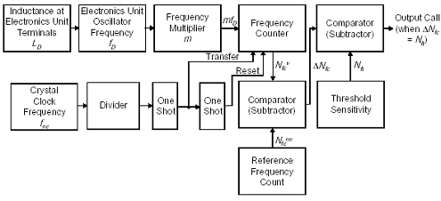
A simplified block diagram of a single-channel, digital frequency-shift electronics unit is illustrated in Figure F-1. The change in inductance at the electronics unit terminals causes a change in the oscillator frequency. The frequency is multiplied by the frequency multiplier. The resultant frequency is transformed into a frequency count by the frequency counter.

Figure F-1. Digital frequency-shift electronics unit block diagram.
The frequency counter is first initialized to zero. Frequency count data are then collected for a preset time frame. The first one-shot module then causes the frequency count to be transferred to the frequency counter and first comparator at the end of the time frame. The second one-shot module resets the frequency counter to zero so that it can collect data for the next time frame. The cycle then repeats.
The first comparator subtracts the reference frequency count stored in memory, which corresponds to the count when no vehicle is present, from the frequency count just transferred, which may or may not correspond to the presence of a vehicle. The count difference is next sent to the second Output Call comparator. If the second comparator finds that the count difference is greater than the threshold sensitivity count, then a vehicle is presumed present and a call is output.
The reference frequency count in memory updates at a specified time interval whenever no change has occurred in the call status over that interval.
The number of oscillator cycles counted by the frequency counter is
 |
(F-1) |
| where | ||
| Tft | = frame time of the frequency counter in s | |
| m | = frequency multiplier | |
| fD | = frequency of electronics unit oscillator in Hz | |
| fnc | = crystal clock frequency in Hz. |
The frame time is assumed to be constant at each sensitivity setting. The response time of the digital frequency-shift electronics unit is equal to the frame time Tft, which in turn is equal to the inverse of the divided crystal clock frequency.
For example, with a frame time of one second, the number of counts Nfc made by the frequency counter is the electronics unit oscillator frequency multiplied by m.
Since the frequency of the electronics unit oscillator changes when a vehicle is present, the count given by the frequency counter will also change. Thus, the presence of a vehicle is ascertained by noting when the change in the output of the frequency counter is above some threshold.
The reference count is measured with no vehicle present and is equal to
 |
(F-2) |
With a vehicle present, the count becomes
 |
(F-3) |
The electronics unit computes the difference in count ΔNfc with and without a vehicle present at the output of the first comparator as
| (F-4) |
Substituting Equations F-2 and F-3 into the above equation yields
 |
(F-5) |
Factoring out m and fnc yields
 |
(F-6) |
Denoting (fDv - fDmv) by ΔfD, we get
 |
(F-7) |
as the difference in count that occurs when a vehicle is present and not present.
A vehicle call is output when the difference count ΔNfc equals the threshold count Nft.
Accordingly when a call is made, one can write
 |
(F-8) |
or
 |
(F-9) |
From Equation 2-51 in Chapter 2, the sensitivity of the digital frequency shift electronics unit is given by
 |
(F-10) |
Upon substituting ΔfD from Equation F-9 into Equation F-10, we obtain
 |
(F-11) |
Since
 |
(F-12) |
the sensitivity becomes
 |
(F-13) |
Thus, the sensitivity of the digital frequency-shift electronics unit is directly proportional to the threshold frequency count Nft, the crystal clock frequency fnc, and the square root of the product of the total inductance LD across the electronics unit terminals and total capacitance CD across the electronics unit terminals (CD includes internal tuning capacitance). Sensitivity is inversely proportional to the oscillator multiplier factor m.
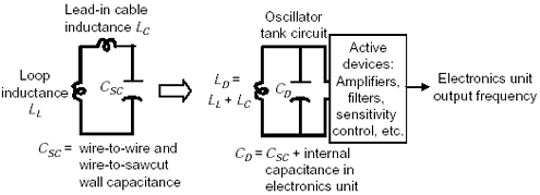
An equivalent electrical circuit showing the inductive and capacitive elements that contribute to LD and CD is shown in Figure F-2.

Figure F-2. Loop-inductive and capacitive elements at electronics unit terminals.
If we define
 |
(F-14) |
then
| (F-15) |
Another form for the sensitivity equation is obtained by substituting
 |
(F-16) |
from Equations F-2 or F-3 into Equation F-11 as

or
 |
(F-17) |
Thus, the frequency shift electronics unit sensitivity is proportional to the frequency threshold count Nft divided by the total number of counts Nfc in the frequency counter.
Previous | Table of Contents | Next
FHWA-HRT-06-139 |