U.S. Department of Transportation
Federal Highway Administration
1200 New Jersey Avenue, SE
Washington, DC 20590
202-366-4000
Federal Highway Administration Research and Technology
Coordinating, Developing, and Delivering Highway Transportation Innovations
 |
| This report is an archived publication and may contain dated technical, contact, and link information |
|
Publication Number: FHWA-HRT-06-139
Date: October 2006 |
| (1) | Grounding of all metallic electrical enclosures is required for safety. If a live conductor touches the metal, a large ‘short circuit current’ flows to ground, thus tripping the circuit breaker. If the metal were not grounded, it would assume the same voltage as the touching conductor and remain so until discharged to ground. When touched, the discharge could occur through the person’s body to ground depending on the resistance of gloves, boots and the material the person is standing on. |
| (1) | A low voltage system is grounded throughout to ensure that any line-to-ground fault is cleared by the circuit breakers prior to doing any permanent power system damage such as melting of cables, etc. The system ground is usually tied to the safety ground. If the two grounds are separated, the following disadvantages occur: |
| (a) | ‘Resistance to ground’ of both system and safety grounds is greater than would be the case if the two were connected together. | |
| (b) | High currents could still flow in the safety ground in the event of cable insulation failures in the enclosure. | |
| (c) | A high degree of coupling, through the earth, is difficult to avoid if the ground rods are in the same local area. | |
| (d) | Where decoupling is possible, voltages (often dangerous) can be possible between the nearby ‘grounded points’. |
| (1) | Lightning induced currents on cables must be given a fast and easy path to ground through protective devices such as lightning arresters, varistors and gas-tube arresters. If the path to ground is not provided properly, the voltage surge ‘spikes’ and resultant current and energy will damage components. Electronic components are particularly susceptible to damage since they operate at very low voltages and high speeds and are not designed to physically absorb any significant energy. |
| (1) | A minimal resistance to ground is desirable. Older versions of the Code called for 10 ohm (Ω) maximum to ground. This requirement is now replaced with a description of the physical grounding materials, or, in the case of a substation, limiting the voltage rise due to a fault to 5000 V. The requirement for 10 Ω was difficult to design and perhaps even more difficult to obtain during installation. | |
| (2) | The resistance to ground depends on several non-exclusive factors: |
| (a) | The number and length of ground rods |
| (b) | The number and length of connecting ground wires in the ground grid |
| (c) | The quality of wiring connections |
| (d) | The resistivity of the earth |
| (e) | The temperature of the earth |
| (f) | The water content of the earth |
| (3) | The last three factors are somewhat weather dependent and are therefore beyond precise design. |
| (1) | The resistivity of the soil, at the site under consideration, is a measure of the resistance to conducting electrical current and is measured in Ohm-meters (Ωm). Representative values are given Table N-1. |
| Soil Type | Resistivity ρ (Ωm) |
|---|---|
Clay, saturated silt |
100 |
Sandy or silty clay |
250 |
Clayey sand or saturated sand |
500 |
Sand |
1500 |
Gravel |
5000 |
Dry sand, rock |
>5000 |
| (2) | The soil classification and ρ values in Table N-1 are left purposely vague since environmental effects can drastically change the resistivity of the soil. Table N-2 shows the typical variation of a nominal resistivity with different soil temperatures. |
| Ground Temperature (°C) | Resistivity ρ (% of nominal) |
|---|---|
| 20 | 73 |
| 10 | 100 |
| 0+ | 139 |
| 0– (freeze) | 303 |
| – 5 | 798 |
| –10 | 3333 |
| (3) | Resistivity varies widely with moisture content as well as temperature, with values a factor of 350% higher for soil in the ‘dry’ state than in the ‘wet’ state. | |
| (4) | In order to custom design a grounding system, the designer would need to know not only the type of soil and its resistivity, but also the condition of future measurements. For this reason, a resistivity of ρ = 100 Ωm is selected as the basis of design for grounding systems. (The system is field measured upon installation and any deficiencies can be made up by installing supplementary facilities.) It should also be noted that Ontario has little or no lightning activity during months when the ground temperature is below the freezing point. |
(1) Resistance to ground for a single ground rod may be calculated from
where
| RG = Resistance to ground in Ohms (Ω) |
| ρ = Soil resistivity in Ohm-meters (Ωm) |
| LR = Rod length in meters (m) |
| aR = Rod radius in meters (m) |
| RR = Resistance to ground of one rod in Ohms (Ω). |
Example 1: for 20 mm dia. x 3 m Rod
Given ρ = 100 Ωm, LR = 3 m, αR = 0.01 m
If the soil is wet and ρ decreases to ρ = 50 Ωm
If the soil is dry and ρ increases to ρ = 300 Ωm
It may be seen that the nominal resistance to ground of 50 Ω usually quoted for a single ground may vary substantially depending on soil type or conditions.
Example 2: for 20 mm dia. x 6 m Rod
Given ρ = 100 Ωm, LR = 6 m, αR = 0.01 m
or for a 100% rod depth increase (over example 1), the resistance to ground is decreased by 44%.
Example 3: for 25 mm dia. x 3 m Rod
Given ρ = 100 Ωm, LR = 3 m, αR = 0.0125 m
or for a 25% increase in rod diameter (over that of Example 1), the resistance to ground is decreased by 3%.
(1) Using the same formula as for a single ground rod,
we have the following examples.
Example 4: for Steel Footing (220 mm dia. x 2300 mm)
Given ρ = 100 Ωm, LR = 2.30 m, αR = 0.110 m
or 26 % "better" than a single rod.
Example 5: for Steel Footing (85 mm dia. x 1830 mm)
Given ρ = 100 Ωm, LR = 1.830 m, αR = 0.043 m
or 12 % "worse" than a single ground rod.
General
(1) For a single plate,
where
| RP = Resistance of plate to ground in Ohms |
| LP = Length in meters |
| WP = Width in meters |
| TP = Thickness in meters. |
Example 6: for 610 x 610 x 6 mm Plate
Given ρ = 100 Ohm, LP = 0.61 m, WP = O.61 m, TP = O.OO6 m

General
| (1) | For the case of a grounding system consisting of a wire grid only, the wire shape forms a ground plane (similar to antenna design), which if buried deep enough, can constitute the most effective part of the grounding system. (Ground rods are normally driven, in any event, in order to penetrate below the frost line.) |
The resistance to ground for a grid system is approximated by

| RW = Resistance of wire grid in Ohms |
| LW = Total Length of grid wires in meters |
| dW = Diameter of wire in meters |
| ZW = Burial depth of grid in meters |
| AW = Plan area covered by grid in square meters. |
Example 7: Using 3 x 3 m grid with cross-tie
 |
Given ρ = 100 Ωm, LW = 5 x 3 = 15 m, ZW = 0.3 m AW = 3 x 3 = 9 sq m, dW = 0.0105 m (#2/0)  |
Example 8: Using 3 x 3 m triangular grid
 |
Given ρ = 100 Ωm, LW = 3 + 3 + 3 = 9 m, ZW = 0.3 m AW = 0.5 x 3 x 3 sin(60o) = 3.90 sq m, dW = 0.0105 m (#2/0) |
General
(1) The combined effect of several rods is similar to the rod resistance acting in parallel and is given by

where
| RMR = Combined resistance of multiple rods to ground in Ohms |
| LR = Rod length in meters |
| n = Number of rods |
| AR = Area covered by the n rods in square meters. |
For 20 mm x 3 m rods,

Example 9: Using four rods on 3 m square
Given ρ = 100 Ωm, αR = 0.01 m, LR = 3 m, n = 4, AR = 3 x 3 = 9 sq m
(Note: rods not connected by wire)
General
(1) It is may be necessary to include both rod and wire grids for service grounds, substations, etc.
The resistance to ground of the combined system is given by

| RG = Total system resistance to ground in Ohms |
| RW = Resistance of wire grid in Ohms (Subsection 3.4) |
| RMR = Resistance of multiple rods in Ohms (Subsection 3.5) |
| RWR = Mutual resistance factor of the wires to the rods |

For 20 mm x 3 m rods,

Example 10: Using 3 x 3 m grid with cross-tie and rods
 |
Given ρ = 100 Ωm, LR = 3 m, αR = 0.01 m, AW = AR = 3 x 3 = 9 sq m, n = 4, ZW = 0.3 m, dW = 0.0105 m (#2/0), LW = 5 x 3 = 15 m, Substituting the given data in the formula, we have  (from Example 9). (from Example 7).  Substituting the above results in the formula for RG, we have If the site soil was clayey sand instead of clay, ρ would be 500 Ωm instead of 100 Ωm (Table 1) and the resistance to ground would be  |
General
(1) A single wire or counterpoise directly buried in earth has a resistance to ground of

where RC = Resistance to ground of buried conductor in Ohms.
Example 11: Using #6 AWG wire
Given ρ = 100 Ωm, ZW = 0.6 m, LW = 50 m, αW = 0.00252 m,

General Formulae
| Single Rod Only: | |
| Single Plate Only: |  |
| Wire Grid Only: |
Multiple Rods Only:

| Multiple Rods and Wire Grid: |
where
Single Wire Only:

The symbols that appear in the above formulae are defined as:
| RG | = | Total resistance to ground of the system in Ohms |
| RR | = | Resistance to ground of a single ground rod in Ohms |
| RP | = | Resistance to ground of a single ground plate in Ohms |
| RW | = | Resistance to ground of a single ground wire in Ohms |
| RMR | = | Resistance to ground of multiple ground rods in Ohms |
| RWR | = | Mutual resistance factor of wires to rods in Ohms |
| RC | = | Resistance to ground of a single buried wire in Ohms |
| LR | = | Length of ground rod in meters |
| LW | = | Length of wire in meters |
| LP | = | Width of plate in meters |
| TP | = | Thickness of plate in meters |
| AW | = | Area of wire grid in square meters |
| AR | = | Area covered by several ground rods in square meters |
| aR | = | Radius of ground rod in meters |
| aW | = | Radius of wire in meters |
| dW | = | Diameter of wire in meters |
| ZW | = | Burial depth of wire in meters |
| n | = | Number of ground rods |
| ρ | = | Soil resistivity in Ohm-meters. |
Useful Formulae
(1) Since the Ministry’s grounding system uses common components of
then the general formulae can be reduced to reflect the physical parameters of the common items as follows:
The foregoing formulae are approximate and may be used where special conditions apply.
(1) The Ministry’s designs for grounding systems are based on the following premises:
| (a) | A resistance to ground of 10 Ω should be obtained in accordance with good practice. | |
| (b) | In cases where 10 Ω to ground is impossible to obtain using practical methods, 25 Ω to ground is the minimum requirement provided that adequate steps are taken to ensure that step and touch voltages do not present a safety problem to workers or the public. | |
| (c) | Every effort is to be made to meet the 10 Ω to ground requirement, where practical, by addition of ground electrodes and wire in the field. | |
| (d) | Since soils and their resistivity vary widely with location and environment respectively, the Ministry’s standard criteria for design is ρ = 100 Ωm. The resistance to ground of the designed system is field checked and any required alterations are made at that time. Where it is obvious to the designer that increased grounding facilities will be required (sand, gravel, rock, etc.), the required facilities can be estimated from Table N-3 and included in the design. | |
| (e) | Table N-3 is derived from the general formulae of Subsection 3.8. | |
| (f) | The following notes apply to Table N-3: |
| (i) | Configuration No.9 may be used with continuous #6 ground wire commonly used for lighting. Grounding at every 5th pole applies. | |
| (ii) | Configurations No. 11 or 12 may be used for grounding in clay or areas that remain damp. Configuration No. 13 should be used as the ‘standard’ design. | |
| (iii) | Configurations No. 15 to 18 indicate the results of adding more wire and rods to the grid. If dry sand, gravel, or rocky areas are unavoidable, the principles illustrated may be extended by manual calculation using the formulae given. | |
| (iv) | Values shown in brackets are for information as a simpler grid would normally be required. | |
| (v) | Values shown are ‘stand alone’ values (isolated ground). An approximation of resistance to ground for any number of the systems, which are tied together with ground wire, may be made by considering the values to be in parallel. |
Problem areas are identified as:
(1) Bedrock or shallow overburden of less than 1 m depth over bedrock:
| (a) | It will be necessary to drill 150 mm (min) holes in the bedrock and backfill these with a cementous iron slag slurry mixture (trade name: ‘Embico’). Note that previously used methods used rock salt as the chief conductor and that this method is no longer recommended due to corrosion. Difficulty in obtaining (and measuring) proper resistance to ground will be encountered as the ground depends, to some extent, on the number of seams between rock layers that are encountered. In this situation, the first design choice would be to locate the object to be grounded away from the rock area. If this is unavoidable, configuration No. 18 in Table N-3 should be used for design and added to during construction if necessary. |
(2) Soil overburden of 1 m to 2 m depth over bedrock:
| (a) | Plates may be used as ground electrodes with the same configurations shown in Table N-3 for rods (depending on type of soil overburden). A minimum of 300 mm of soil should be left between the rock and plate and the #2/0 wire grid. |
(3) Rock Fill
| (a) | Areas of rock fill can be assumed to have a resistivity in excess of 10,000 Wm. A previously used method was to run two parallel runs of #2/0 wire through the voids in the rock fill to a location suitable for use of normal grounding methods. The method causes large voltages to appear at the cabinet due to the high inductance of the leads to ground and should be avoided by placing at least 2.0 m of earth fill over the rock fill. |
| Ground System Configuration | Description | Normal Use | Resistance to Ground (Ω)in Clay (ρ=100Ωm) | Resistance to Ground (Ω)in Sandy Clay (ρ=200Ωm) | Resistance to Ground (Ω)in Clayey Sand (ρ=500Ωm) | Resistance to Ground (Ω)in Sand (ρ=1500Ωm) | Resistance to Ground (Ω)in Sand, Gravel (ρ=5000Ωm) |
|---|---|---|---|---|---|---|---|
| 1.Single 20 mm x 3 m rod | Additionto system | 32 | 80 | 160 | 480 | 1610 | |
| 2.Single 220 mm dia. x 2300 mm steel footing | Poles(requires additional system) | 28 | 70 | 140 | 420 | 1400 | |
| 3.Single 85 mm dia. x 1830 mm steel footing | Poles,cabinets (requires additional system) | 40 | 100 | 200 | 600 | 2000 | |
| 4.610 x 610 x 6 mm plate | Rockoverburden 0.6 to 2.0 m | 46 | 115 | 230 | 690 | 2300 | |
| 5.Single #6 wire, bare, 3 m long | Additionto system | 41 | 103 | 205 | 615 | 2050 | |
| 6.Single #2/0 wire, bare, 3 m long | Additionto system | 38 | 95 | 190 | 570 | 1900 | |
| 7.Single #6 wire, 2 rods | Service | 19 | 38 | 95 | 290 | 950 | |
| 8.Single #2/0 wire, 2 plates | Servicein overburden | 27 | 54 | 140 | 410 | 1400 | |
| 9.220 mm dia. x 2300 mm steel footing, #6 wire, 1 rod | Poles | 19 | 38 | 95 | 285 | 950 | |
| 10.85 mm dia. X 1830 mm steel footing, #6 wire, 1 rod | Poles | 16 | 34 | 80 | 240 | 800 | |
 |
11.85 mm dia. x 1830 mm steel footing, #2/0 wire, 2 rods | Cabinets | 14 | 28 | 70 | 210 | 700 |
 |
12.85 mm dia. x 1830 mm steel footing, #2/0 wire, 3 rods | Cabinets | 13 | 26 | 65 | 195 | 650 |
 |
13.85 mm dia. x 1830 mm steel footing, #2/0 wire, 4 rods | Cabinets | 10 | 20 | 50 | 150 | 250 |
 |
14.#2/0 wire, 4 rods | Service Anyfor ρ < 125 Ωm | 11 | 22 | 55 | 165 | 550 |
 |
15.#2/0 wire, 4 rods, 2 ties | Anyfor ρ < 125 Ωm | 11 | 22 | 55 | 165 | 550 |
 |
16.#2/0 wire, 4 rods, 2 ties, 4 tails | Anyfor 125 < ρ < 150 Ωm | (9) | 18 | 45 | 135 | 450 |
 |
17.#2/0 wire, 4 rods, 2 ties, 8 tails | Anyfor 150 < ρ < 200 Ωm | (6) | 12 | 30 | 90 | 300 |
 |
18.#2/0 wire, 8 rods, 6 ties | Anyfor 200 < ρ < 350 Ωm | (5) | 10 | 25 | 75 | 250 |
| (1) | From the examples in the foregoing sections, it is immediately obvious that obtaining a 10 Ω resistance to ground is difficult in soils with high resistivity. | |
| (2) | The effect of ground rod diameter is small. About 8% less resistance to ground is obtained by using a 25 mm diameter rod instead of a 20 mm rod. Much better results are obtained by making ground rods longer rather than thicker. | |
| (3) | The effect of electrode material (copper or steel) has negligible effect on results since the resistivity of all metals is much less than that of all soils. | |
| (4) | Ground rod spacing should be kept within one rod length spacing of each other. | |
| (5) | The effect of the size and type of wire interconnecting the ground rods has little effect on results. The #2/0 AWG cable usually used is sized to withstand a 50,000 ampere lightning discharge without complete melting. | |
| (6) | The upper 1.0 m of ground rod does not have much effect, even in wet soil. A minimum depth of 2.0 m gives about 25% more resistance to ground than the 3.0 m standard depth rod. | |
| (7) | In order to design proper grounding, a soils classification at the intended location should be obtained from the Regional Geotechnical Office (if not on the ‘Soils Profile’ or indicated on borehole logs included with contract drawings) and District personnel should be consulted. | |
| (8) | If the equipment to be grounded will be in a new fill location, the fill should not be composed of sand, gravel, rock and the like (if practical). A note on the grading drawings should be added where necessary: ‘Fill in the area of (equipment) to be cohesive material only or similar.’ | |
| (9) | Table N-3 gives the number of ground rods (20 mm x 3.0 m) and grid configurations required for various classes of soil. Where there is not an apparent site problem, ground designs corresponding to ρ = 100 Ωm should be used by the designer. Where necessary after testing, the design may be adjusted during construction. Where it is not practically possible to obtain 10 Ω to ground, an absolute minimum of 25 Ω may be used. |
The effects of lightning on outdoor electrical and electronic equipment can be costly. Damage from lightning may result from:
Since it is not practical to protect outdoor equipment against direct strokes, protective systems apply to the prevention or handling of surges and transients. The protective systems consist of the application of proper ground, suppression, and shunting devices.
Since weather is somewhat unpredictable, protection design is based on the following probabilities:
The design criteria adopted for protection of the Ministry’s electronic equipment are:
Figure N-1 indicates waveforms and timing of lightning protection devices.
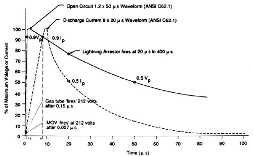
Note that the times needed for protection are much too fast to allow power circuit protection devices such as breakers, fuse, lightning arresters etc. to operate effectively. However, devices such as gas tubes and metal oxide varistors (MOVs) will initiate protection at about 0.15 μs and 0.007 μs, respectively.
Surges in any equipment including cables, poles, etc. can be induced by lightning strikes as far as 6 km away. Surges on overhead high voltage lines are grounded through lightning arresters at transformer locations.
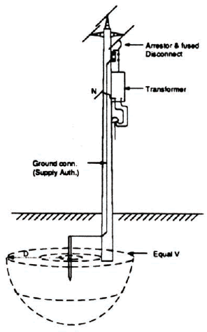
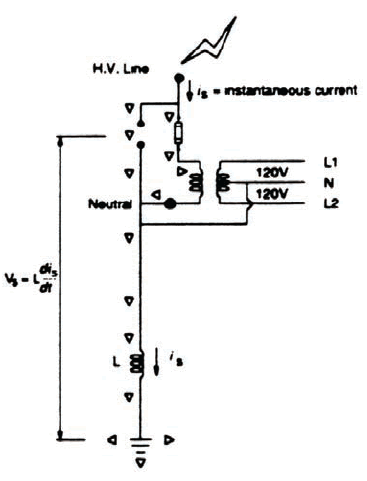
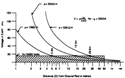
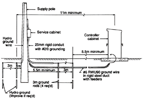
Figure N-2 shows the voltage and current distribution through the earth near the bottom of the utility pole. For the design value of resistivity ρ = 100 Ωm, a voltage of 15,000 volts would be transferred through the earth for a distance of 5.3 m. It is therefore necessary to keep the service ground a minimum distance from the Hydro ground as indicated in Figure N-3. Since the designer seldom knows where the Hydro ground line is located, the convention of 5.5 m to the center of the pole is used as a design practice. Note that a large voltage will appear at the service ‘SN’ due to the Ldi/dt voltage on the grounding cable.
 |  |
 |
Traffic signal systems contain many other sources of transient voltages and currents within the controller cabinet. These sources are not considered as severe as the energy surge through the service neutral and all have protection devices installed within the cabinet. Some sources are:
| (a) | Detector Loops—inductive loop detector electronics units are protected internally with their own lightning arrester and are also provided with external MOVs at the input file. Failure rate due to lightning damage is very low as the voltage impressed on a loop is caused by capacitive effects. | |
| (b) | Detector Cable—the possibility of induced currents caused by transient voltages in the earth is minimized by shielding the detector cable and leaving both ends of the shield cut off. | |
| (c) | Signal Cable—signal cable is shielded by metal poles (above ground), but is subject to induced currents caused by transient voltages in the earth. The load switches and the AC-terminals of the cabinet are protected by MOVs and the failure rate is low. | |
| (d) | Direct Hits on Cabinet—although nothing can be done to ensure a complete lack of damage, the controller cabinet may be considered to be protected by an umbrella cone of 30o from an overhead line and somewhat protected by a 45o cone. It is not desirable, however, to install the cabinet directly under the lines due to possible electromagnetic interference. The cabinet location (Figure N-4) should be:
| |
| (e) | Direct Hits on Poles or Equipment—this condition would cause severe damage. The method of mitigating possible damage effects consists of installing a #6 AWG RWU 90 (green) system ground wire connecting all poles and intersection equipment and installing a ground rod on each corner. Connection of the system ground around the intersection should be made at one point only (the service ground bus) as indicated in Figure N-5. |
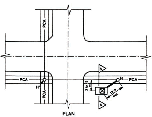 |
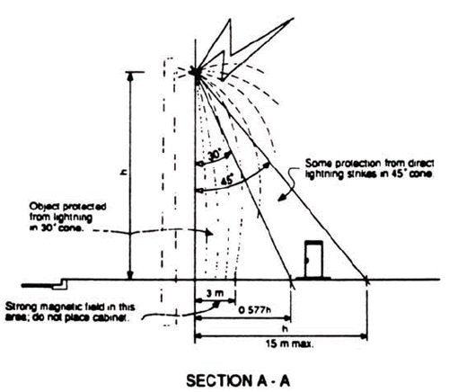 |
Figure N-4. Controller cabinet location for best lightning protection.
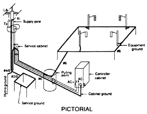 |
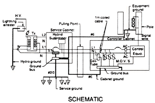 |
Figure N-5. Signal grounding system (with or without lighting). No ground electrodes at cabinet.
(1) Design standard grounding system under normal circumstances (Figures N-3 and N-5):
(2) Use improved design as per Table N-3 for grounds in sand, gravel, or rock. Consult Geotechnical Information and District Maintenance.
(3) Both ends of the detector cable shield should be cut off and left unconnected.
(4) Locate controller at least 11 m from a hydro pole and at least 3 m horizontally from overhead lines. Locate controller 1.5 m clear minimum from metal objects such as poles, fences, and guide rails.
| (1) | Biddle Instruments, Getting Down to Earth: A Manual on Earth Resistance Testing for Practical Man, 4th ed., 1981. | |
| (2) | Bodle, D., Electrical Protection Guide for Land-Based Radio Facilities, Joslyn Electronic Systems, 1971. | |
| (3) | Burns, G.A, “Lightning Damage to Tank-Gauging Equipment Solved by Modification Instead of Replacement,” Oil and Gas Journal, pg. 93, September 14, 1981. | |
| (4) | Canadian Standards Association, Canadian Electrical Code Part I, Section 10, Grounding and Bonding, 1987. | |
| (5) | Carpenter, R.B., “Total Isolation from Lightning Influences,” IEEE Transactions on Industry Applications, Vol. 1A-17, No. 3, pg. 334, May/June 1981. | |
| (6) | Cunagin, W.D. and Avoub, N.A., Lightning Protection Hardware and Techniques for Electronic Traffic Control Equipment, Federal Highway Administration, February, 1986. | |
| (7) | Dasen, M., Insulation Tester – Megger, Algonquin College. | |
| (8) | Dasen, M., Meg-Earth Tester, A1gonquin College. | |
| (9) | Denny, H.W. and Rohrbaugh, J.P., “Transient Protection, Grounding, and Shielding of Electronic Traffic Control Equipment,” NCH RP Report 317, Transportation Research Board, June, 1988. | |
| (10) | Edco, Inc., Lightning Protection for Traffic Control, Edco Technical Bulletin No. 200-01, May, 1978. | |
| (11) | Edco Inc. of Florida, Installation Technical Bulletin # 100484, 1984. | |
| (12) | Epstein. B.M., “For Best Results, Treat Power and Computer Requirements as One System,” EC&M, pg. 130, August 1986. | |
| (13) | Fink, D.G and Beaty, H.W., Standard Handbook for Electrical Engineers, 11th Edition, 1978. | |
| (14) | Freund, A, “Protecting Computers from Transients,” EC&M, pg. 65, April 1987. | |
| (15) | General Electric, Transient Voltage Suppression, 3rd Edition. | |
| (16) | Gunn, R., “Facility Noise Control from the Ground Up,” EC&M, pg. 56, April 1987. | |
| (17) | Harder, J.E., Hughes, A.E., and Vosicky, J., “Analytical Method for Coordination of Surge Arresters with Current-Limiting Fuses,” IEEE Transactions on Industry Applications, Vol. lA-17, No. 5, pg. 445, September/October 1981. | |
| (18) | Institute of Electrical and Electronic Engineers, Inc., IEEE Guide for Radio Methods of Measuring Earth Conductivity, IEEE Standard 356-1974. | |
| (19) | Institute of Electrical and Electronic Engineers, Inc., IEEE Guide for Safety in Substation Grounding. IEEE Standard 80-1976. | |
| (20) | Institute of Electrical and Electronic Engineers, Inc., IEEE Guide for the Installation of Electrical Equipment to Minimize Electrical Noise Inputs to Controllers from External Sources, IEEE Standard 518-1982. | |
| (21) | Institute of Electrical and Electronic Engineers, Inc., ”IEEE Standard Procedures for the Measurement of Radio Noise from Overhead Power Lines,” IEEE Transactions on Power Apparatus and Systems, Vol. Pas -100, No. 8, August 1981. | |
| (22) | Institute of Electrical and Electronic Engineers, Inc., “Modeling Current-Limiting Surge Arresters,” IEEE Transactions on Power Apparatus and Systems, Vol. Pas -100, No.8, August 1981. | |
| (23) | Lee, W.R., “The Dangers of Lightning,” ETI Canada, pg. 27, November 1978. | |
| (24) | Michaels, E.C., “Principles and Techniques for Grounding and Bonding in Hazardous( Classified )Locations,” Plant Engineering, pg. 133, September 17, 1981. | |
| (25) | Mims, F.M., “Introducing the Varistor,” Computers and Electronics, pg. 88, May 1983. | |
| (26) | Ontario Hydro Inspection Department, “Electrical Inspection, Provincial Government,” Electrical Inspection Guide 26-4, December 1975. | |
| (27) | Ontario Hydro Inspection Department, “Pub1ic Roads - Electrical Devices,” Electrical Inspection Guide 11-3, August 1984. | |
| (28) | Ontario Hydro Inspection Department, “Rule 10-208: Grounding Connections for Two or More Buildings or Structures,” Bulletin 10-6-0, April 1987. | |
| (29) | Plumber, J.A. and Crouch, K.E., Lightning Protection for Traffic Control Systems, National Aeronautics and Space Administration, 1978. | |
| (30) | Schwarz, S.J., “Analytical Expressions for the Resistance of Grounding Systems,” presented at the AIEE Summer and Pacific General Meeting, Los Angeles, June 1954. | |
| (31) | Stifter, F.J., “Power-Line Disturbances,” Computers and Electronics, pg. 35, October, 1983. | |
| (32) | Thomas, P., Investigative Report - Lightning Problems on 170/332 Traffic Control Systems, Ministry of Transportation of Ontario, June 1985. | |
| (33) | Waterson, A. and Maher, P., “Computer Power - Problems and Solutions,” EC&M, pg. 67, December 1982. | |
| (34) | Westinghouse Electric Corporation, Electrical Transmission and Distribution Reference Book, 1950. | |
| (35) | “Equipment, Manuals and Procedures Evaluation for the Design and Maintenance of Traffic Signal Systems,” Report No. 2, Grounding, Ministry of Transportation of Ontario, May 1988. |
Previous | Table of Contents | Next
FHWA-HRT-06-139 |